AUXSOL ASN Series User manual

ASN - 15TL
ASN - 17TL
ASN - 20TL
ASN - 23TL
ASN - 25TL
Ningbo AUX Solar Technology Co., Ltd.
No.17 Fenglin Road, Cicheng Town, Jiangbei District, Ningbo City,
Zhejiang Province, China
INSTALLATION
OPERATION MANUAL
ASN series
ASN - 5TL
ASN - 6TL
ASN - 8TL
ASN - 10TL
ASN - 12TL

Summary
Applicable products
Applicable staff
Symbol definition
CONTENT
PREFACE
1 OPEN THE CARTON TO CHECK
2 SAFETY PRECAUTIONS
3 INTRODUCTION
3.1 Products introduction
3.2 Outlook introduction
3.3 Dimension
3.4 Display description
2.1 General safety
2.2 PV string safety
2.3 Inverter safety
2.4 Personnel requirements
1.1 Inspection before acceptance
1.2 Packing list
1.3 Storage
1
1
1
1
4
4
5
5
2
2
3
6
6
7
7

1
This document is applicable to the following 10 types of AUX ASN series three-phase on grid inverter:
ASN - 5TL / ASN - 6TL / ASN - 8TL / ASN - 10TL / ASN - 12TL
ASN - 15TL / ASN - 17TL / ASN - 20TL / ASN - 23TL / ASN - 25TL
5.1 Installation requirements
5.2 Installation of inverter
5.3 Electrical connection
4 APPLICATION
5 INSTALLATION
4.1 Grid form
4.2 Application scenario
4.3 Application mode
4.4 Function characteristics
8
9
10
10
11
14
15
6.1 Check before power-on
6.2 Power on the equipment
6.3 Set inverter parameters via APP
6.4 Power off the equipment
6.5 Equipment removal
6.6 Equipment scrapping
6.7 Trouble shooting
6.8 Regular maintenance
6 EQUIPMENT COMMISSIONING
AND MAINTENANCE
7 TECHNICAL PARAMETER
24
24
25
25
26
26
26
29
30
PREFACE
Summary
Applicable products
This document mainly introduces the installation, electrical connection, adjustment, maintenance and
troubleshooting methods of ASN series Three phase on grid solar inverter. Before installing and using
the inverter, please read this manual carefully to understand the safety information and get familiar with
the functions and characteristics of the inverter. The document may be updated from time to time.
Please obtain the latest version of the information and other product information from the official
website.
Applicable staff
It is only applicable to professionals who are familiar with local regulations and standards and electrical
system, have received professional training and are familiar with the relevant knowledge of the product.
Symbol definition
To better use this manual, the following symbols are used to highlight important information. Please
read the symbols and instructions carefully.
!
!
Danger:
Indicates a highly potential danger that, if not avoided, could result in death or serious
injury to personnel.
Watch out:
Emphasizing and supplementing the content may also provide tips or tricks for
optimizing product usage, which can help you solve a problem or save you time.
Watch out:
Indicates a low level of potential danger that, if not avoided, may result in moderate or
mild injury to personnel.
Warning:
Indicates a moderate potential hazard, which could lead to death or serious injury if not
avoided.

2 3
Inverter
User manual
Quick installation manual
PV terminals (+, -)
Wall-mounting bracket
Hangers
Self tapping screws+bolt expansion
Combination screws
Datalogger
Inspection report
Rubber
AC terminal waterproof cover
Waterproof joint
Combination screws
Power cable OT terminals
Current transformer
Output signal connector
Meter kit
ASN-5~25TL
ASN-5~25TL
ASN-5~25TL
ASN-5~25TL
ASN-5~25TL
M6*50+Φ10*45
M5×12
ASN-5~25TL
30*20*25
M4×12
14-5
1
2
3
4
5
6
7
8
9
10
11
12
13
14
15
16
17
18
1
2
3
4
5
6
10 11 12
16 17 18
13 14 15
7
8
9
pcs
pcs
pcs
pair
pcs
pcs
set
pcs
pcs
pcs
pcs
pcs
pcs
pcs
pcs
set
set
set
1
1
1
*
1
2
3
5
1
1
1
1
1
5
6
1
1
1
optional
optional
optional
Before signing for the product, please carefully check the following contents:
1.1 Inspection before acceptance
1.2 Packing list
1 OPEN THE CARTON TO CHECK
!
Watch out:
• The number of PV DC input terminals matches the number of inverter DC input terminals.
• The datalogger and electricity meter kit are provided as optional, please refer to the actual situation.
Check the outer packaging for any damage, such as deformation, holes, cracks, or other signs that
may cause damage to the equipment inside the packaging. If there is any damage, do not open the
packaging and contact your dealer.
Check if the inverter model is correct. If there is any discrepancy, do not open the packaging and
contact your dealer.
Check whether the type and quantity of delivered items are correct, and whether there is any damage
to the appearance. If there is any damage, please contact your dealer.
•
•
•
If the inverter is not put into use immediately, please store it according to the following requirements:
Make sure that the outer packing box is not removed.
Make sure that the storage temperature is always - 40 °C~+70 °C and the storage relative humidity is
always 0~100% without condensation.
Make sure the inverter stacking height and direction are placed according to the label on the packing
box.
Make sure there is no risk of toppling the inverter after stacking.
Regular inspection is required during storage. If the package is damaged due to insect and rat bite,
the packaging materials shall be replaced in time.
The inverter shall be put into use after being stored for a long time and inspected and confirmed by
professionals.
1.3 Storage
•
•
•
•
•
•
No. Description Model Unit QTY Remark

4 5
2 SAFETY PRECAUTIONS
2.1 General safety
2.2 PV string safety
!
Watch out:
The inverter has been designed and tested in strict accordance with safety regulations, but as
electrical equipment, the relevant safety instructions must be observed before any operation on the
equipment. Improper operation may lead to serious injury or property damage.
!
Due to product version upgrading or other reasons, the document content will be updated from
time to time. If there is no special agreement, the document content cannot replace the safety
precautions in the product label. All descriptions in this document are for guidance only.
Please read this document carefully for products and precautions before installing the equipment.
Professional and qualified electrical technicians who shall be familiar with the relevant standards
and safety specifications of the project site must carry out all equipment operations.
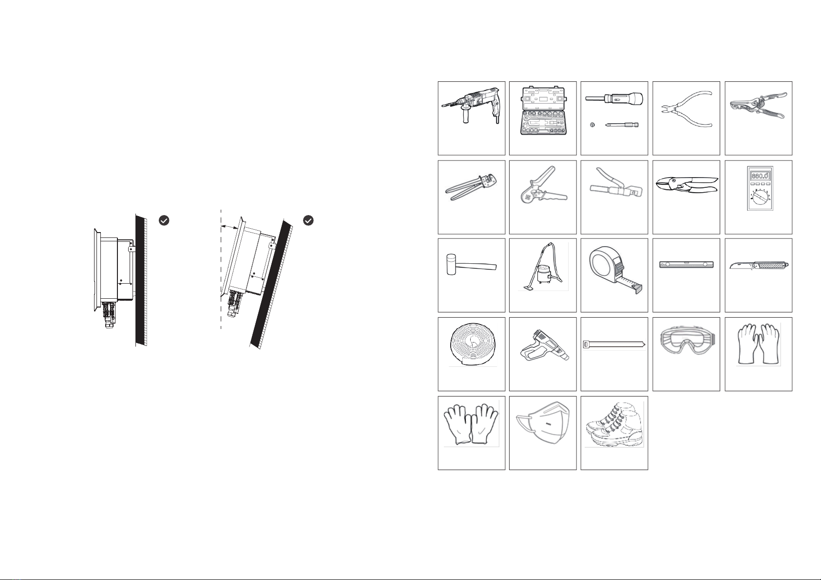
Insulation tools and personal protective equipment shall be used to ensure personal safety during
inverter operation. Electrostatic gloves, wrist strap and antistatic clothing shall be worn when
contacting with electronic devices to protect the inverter from electrostatic damage.
Equipment damage or personal injury caused by inverter not installed, used or configured in
accordance with the requirements of this document or corresponding user manual is not within
the responsibility scope of equipment manufacturer.
Please use the DC wiring terminals provided with the box to connect the inverter DC cable. If other
types of DC wiring terminals are used, serious consequences may be caused, and the equipment
damage caused thereby is not within the scope of the equipment manufacturer.
The solar array (solar panel) will have DC high voltage.
PV panel used with inverters must have IEC 61730 class A rating or other equivalent standard
class.
Make sure good grounding of component frame and support system.
Do not ground the PV array positive (+) or negative (-) as this may cause serious damage to the
inverter.
Make sure that the DC cables are firmly connected without looseness after connection.
Use a multimeter to measure the positive and negative electrodes of the DC cable. Make sure
that the positive and negative electrodes are correct, no reverse connection occurs and the
voltage is within the allowable range.
Do not connect the same PV string to multiple inverters, or the inverter may be damaged.
In order to reduce the risk of fire, the inverter connected circuit requires an overcurrent protection
device (OCPD). DC OCPD shall be installed according to local requirements. All PV power
supplies and circuit conductors shall have disconnect connections in accordance with NEC
Article 690, Part II.
The safety precautions contained in this document must always be observed when operating the equipment.
•
•
•
•
•
•
•
•
•
•
•
•
•
Watch out:
Danger:
Warning:
2.4 Personnel requirements
!
Personnel responsible for installing and maintaining equipment must first undergo strict training,
understand various safety precautions, and master the correct operating methods.
Only qualified professionals or trained personnel are allowed to install, operate, maintain, or
replace equipment or components.
2.3 Inverter safety
Please connect the inverter AC cable with the AC wiring terminals provided with the box. If other
types of DC wiring terminals are used, serious consequences may be caused, and the equipment
damage caused thereby is not within the scope of the equipment manufacturer.
Danger of electric shock. There are no serviceable parts inside the machine. Please do not
disassemble it. Please obtain service from qualified and recognized service technicians.
Make sure that the voltage and frequency of the grid connection access point meet the inverter grid
connection specifications.
It is recommended to add circuit breaker or fuse and other protective devices at the AC side of the
inverter, and the specification of the protective device shall be 1.25 times greater than the
maximum AC output current of the inverter.
The protective ground wire of inverter must be firmly connected to make sure that the impedance
between neutral wire and ground wire is less than 10 Ω.
Copper core cable is recommended for AC output cable.
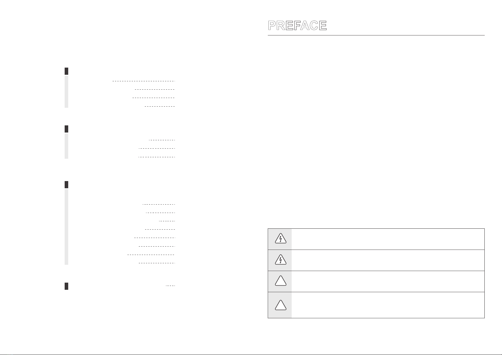
Identifications on inverter box are as follows:
Danger of high voltage. There is high
voltage when the inverter is operating.
When operating the inverter, make sure the
inverter is powered off.
Time delay discharge. Wait for 5 minutes
after the equipment is powered off until the
equipment is fully discharged.
Please read the product manual carefully
before operating the equipment.
Potential hazards after equipment
operation. Please take protective
measures during operation.
There is high temperature on the inverter
surface, so do not touch it when the
equipment is running, otherwise, it may
cause scald.
Connection point of protective earthing
wire.
CE symbol
The equipment shall not be treated as
domestic garbage. Please treat the
equipment according to local laws and
regulations or send it back to the
equipment manufacturer.
5min
•
•
•
•
•
•
•
•
Danger:
Warning:
Watch out:

6 7
25kg
25kg
25kg
25kg
25kg
455 × 462 × 214mm
455 × 462× 214mm
455 × 462 × 214mm
455 × 462 × 214mm
455 × 462 × 214mm
ASN - 15TL
ASN - 17TL
ASN - 20TL
ASN - 23TL
ASN - 25TL
SizeWeightModel
25kg
25kg
25kg
25kg
25kg
455 × 462 × 214mm
455 × 462 × 214mm
455 × 462 × 214mm
455 × 462× 214mm
455 × 462 × 214mm
ASN - 5TL
ASN - 6TL
ASN - 8TL
ASN - 10TL
ASN - 12TL
SizeWeightModel
1
2
3 4 6
5 7
LED indicator light
DC switch
PV DC port
Ground terminal
1
2
3
4
5
6
7
Indicates the working status of the inverter
Connect PV module with PV wiring connector
Smart meters can be connected via RS485
Connect AC Utility/national grid supply
3.4 Display description
Light strip display
455mm
229mm
13.5mm
105mm
105mm
124mm
214mm
30mm
462mm 233.5mm
100mm
3 INTRODUCTION
The AUX ASN series three-phase on grid inverter integrates the energy management system in the PV
system to control and optimize the energy flow, adapt to the requirements of the smart grid and output
the power generated in the PV system to the utility/national grid.
3.1 Products introduction
3.2 Outlook introduction
No. Component Description
Meter communication
port
Communication
module port
Utility/national grid
power interface (black)
Control DC input on or off (warning: this switch does not have breaking
capacity and is prohibited to operate when the machine is running)
The communication module can be connected via RS485, supporting
optional communication modules such as bluetooth, Wi-Fi and 4G
3.3 Dimension
DescriptionStatusIndicator diagram
Light strip
Light strip
Light strip
Light strip
Green always on
Green flashes
Yellow flashes
Red always on
Inverter is generating electricity
Inverter standby
Inverter alarm
Inverter fault

98
Transformer Transformer
L1
L2
L3
N
PE
L1
L2
L3
N
PE
L1
L2
L3
PEN
L1
L2
L3
N
L1 L2 L3 N PE
ASN series
L1 L2 L3 N PE
ASN series
L1 L2 L3 N PE
ASN series
L1 L2 L3 N PE
ASN series
TN-S TN-C
TN-C-S TT AC circuit breaker
≥400
≥400
≥400
≥400
≥400
32
63
63
63
63
ASN - 15TL
ASN - 17TL
ASN - 20TL
ASN - 23TL
ASN - 25TL
Current(A)Voltage(Vac)Model
≥400
≥400
≥400
≥400
≥400
16
16
16
25
25
ASN - 5TL
ASN - 6TL
ASN - 8TL
ASN - 10TL
ASN - 12TL
Current(A)Voltage(Vac)Model
1
2
3
4
AC GRID
CT
4.1 Grid form
4 APPLICATION
!To ensure the normal operation of inverter, it is recommended to be applied to the
network with N-wire.
The voltage of N to PE should be less than 10V.
•
•
Watch out:
PV systems are not suitable for connecting devices that rely on stable power supply, such as
life-sustaining medical equipment. Please ensure that the power outage of the system does not
cause personal injury.
When the inverter is protected for a single time, the inverter can be automatically restarted.
4.2 Application scenario
Warning:
•
•
Power line
Communication or sampling line
PV string assembly
Inverter
AC circuit breaker
Smart meter
1
2
3
4
No. Component Description
PV string consists of PV modules connected in series
ASN series on grid inverter
Optional
Used for inverter and load protection and for interrupting AC supply
during maintenance
Load

1110
-30°C~60°C
0%~100%RH
IP66
altitude
4000m
≥500mm ≥500mm
≥500mm
≥500 ≥500 ≥500
≥500mm
4.3 Application mode
4.3.1 Full grid connection
4.4.1 Power derating
If no load is required, all energy of the inverter can be supplied to the utility/national grid to realize
full grid connection of power generation.
4.4 Function characteristics
The inverter will automatically reduce the output power when the operating environment is not ideal.
The following factors may cause power derating, so please try to avoid them during use:
• Unfavorable environmental conditions such as direct sunlight, high temperatures, etc.
• The inverter's output power percentage has been limited by the app or web-end settings.
• Variation with grid voltage frequency.
• High input voltage.
• High input current value.
5.1.1 Environmental requirements
The protection class of inverter is IP66, which can be installed indoor and outdoor.
Equipment shall not be installed in flammable, explosive and corrosive environment.
The installation position shall be kept away from the accessible range of children and the position easy to be touched.
High temperatures may be present on the surface when the equipment is in operation to prevent burns.
The installation position shall avoid the water pipe and cable in the wall to avoid danger during punching.
The inverter shall avoid salt fog areas and installation environments such as sunshine, rain and snow. It is
recommended to install the inverter in a sheltered installation position. If necessary, a sunshade can be erected.
When installing the inverter, certain space shall be reserved around the inverter to ensure sufficient installation and
heat dissipation space.
Under the installation scenario of multiple inverters, when the space is sufficient, the installation mode of "straight
line" is recommended, When the space is insufficient, it is recommended to install the product in a zig-zag manner.
It is not recommended to install multiple inverters by overlapping.
The installation height of the equipment shall be convenient for operation and maintenance, ensure that the
equipment indicator lights, all labels are easy to see, and the terminal blocks are easy to operate.
The inverter is installed at an altitude lower than the maximum working altitude of 4000m.
Keep away from strong magnetic field environment to avoid electromagnetic interference. If there is a radio station
near the installation location or wireless communication equipment below 30MHz, please install the equipment
according to the following requirements:
Ferrite core with multi-circle winding or low-pass EMI filter at inverter DC input or AC output.
The distance between inverter and wireless electromagnetic interference equipment exceeds 30m.
5 INSTALLATION
5.1 Installation requirements
•
•
•
•
•
•
•
•
•
•

12 13
≤15°
Installation carriers must not be flammable and must be fire resistant.
Please make sure that the mounting carrier is solid and reliable and can bear the weight of inverter.
The equipment will vibrate during operation, so do not install it on the carrier with poor sound insulation,
so as to avoid disturbance to residents in the living area caused by the noise generated by the
equipment during operation.
5.1.2 Carrier requirements
Recommended inverter installation angle: vertical or pitching ≤ 15°.
Do not invert, tilt forward, tilt backward beyond the angle and install the inverter horizontally.
5.1.3 Installation angle requirements
The following installation tools are recommended for installation. Other auxiliary tools can be used on
site if necessary.
5.1.4 Installation tool requirements
Percussion drill Sockets tool box Torque screw
driver Diagonal pliers Wire stripper
Crimping pliers Pressing terminal
crimping plier Hydraulic tongs Wire cutter Multimeter
(Vdc range>1000V)
Rubber hammer Vacuum cleaner Tape measure Levelling
instrument Electrician's knife
Heat shrinkable
sleeve Air heater Cable ties Goggles Insulating gloves
Protective gloves Respirator Protective shoes
•
•
•
•
•

14 15
!
5.2.2 Installation of inverter
105mm
13.5mm
105mm
M5
2.0 N.m
M5
2.0 N.m
!
Transportation, turnover, installation and other operations must meet the requirements of national
and regional laws and regulations and relevant standards.
Please equip corresponding personnel according to the weight of the equipment to prevent the
equipment from exceeding the weight range that can be handled by human body and damaging
personnel.
Wear safety gloves to avoid injury.
Please make sure that the equipment is balanced during handling to avoid dropping.
5.2.1 Handling inverter
5.2 Installation of inverter
Watch out:
•
•
•
•
When drilling holes, make sure that the drilling position is kept away from water pipes, cables, etc.
in the wall to avoid danger.
Wear goggles and dust mask when punching to avoid dust inhalation into respiratory tract or into
eyes.
Make sure that the inverter is securely installed to prevent injuries from falling.
Watch out:
•
•
•
The protective grounding of the crate shell cannot replace the protective grounding wire of the AC
output port. When wiring, ensure that the protective grounding wires at the two places are reliably
connected.
In case of multiple inverters, make sure that the protective earthing point of all inverter crate
enclosures is equipotentially connected.
To improve the corrosion resistance of the terminal, it is recommended to apply silicone or paint
on the external of the grounding terminal for protection after the connection and installation of the
protective ground wire.
Please prepare the protective ground wire, and the recommended specification:
Type: Outdoor single-core copper wire
Conductor sectional area: 4-6mm² ( 12 - 10AWG )
5.3.2 Connecting protective earth wire
!When making electrical connection, please wear safety shoes, protective gloves, insulating gloves
and other personal protective equipment as required.
Only professionals are allowed to carry out operations related to electrical connection.
Specifications of all operation, cables and components used in electrical connection shall comply
with local laws and regulations.
Before electrical connection, please disconnect the DC switch and AC output switch of inverter to
make sure that the equipment is powered off. It is strictly forbidden to operate with electricity,
otherwise, electric shock and other hazards may occur.
Cables of the same type shall be bound together and arranged separately from cables of different
types. It is forbidden to wind or cross cables.
If the cable bears too much tension, it may lead to poor wiring. When wiring, please reserve a
certain length of the cable before connecting to the inverter wiring port.
When crimping the connecting terminal, please make sure that the conductor part of the cable is
fully contacted with the connecting terminal, and do not crimp the cable insulation skin together
with the connecting terminal, otherwise, the equipment may be unable to operate, or the inverter
terminal block may be damaged due to heating due to unreliable connection after operation.
5.3.1 Safety precautions
5.3 Electrical connection
Danger:
•
•
•
•
•
•
•
•
•
•
•
Watch out:
Warning:

1716
Click
Click
Make sure PV polarity is right,
PV voltage≤1100V
PV string output does not support grounding. Before connecting PV string to inverter, please make
sure that the minimum insulation resistance to ground of PV string meets the minimum insulation
impedance requirements (R=maximum input voltage/30mA).
Make sure that the DC cables are firmly connected without looseness after connection.
Use a multimeter to measure the positive and negative electrodes of the DC cable and ensure that
the positive and negative electrodes are correct without reverse connection, and the voltage is
within the allowable range.
Do not connect the same PV string to multiple inverters, otherwise the inverter may be damaged.
Please make sure that the maximum short circuit current and maximum input voltage of each
MPPT are within the allowable range of the inverter.
Please make sure that the positive electrode of the PV string is connected to the PV port+of the
inverter, and the negative electrode of the PV string is connected to the PV port - of the inverter.
Please prepare your own PV input cable. Recommended specification:
Type: Outdoor PV multi-core copper wire
conductor cross-section:4-6mm² ( 12 - 10AWG )
Outer diameter of conductor insulation layer: φ3~7mm
5.3.3 Connect PV input cable
Danger:
•
•
•
•
•
•
•
Warning:
7-10 mm 7-10 mm crimping pliers
4mm2 ≤ S ≤ 6mm2

18 19
L=E+(2-3)mm
≤50mm
E
C
ASN-5TL~ASN-12TL 4-6mm212-18mm
ASN-15TL~ASN-20TL
ASN-23TL~ASN-25TL
6-12mm218-25mm
7-16mm218-25mm
CModel D
D
1
2
3
M5
2.0 N.m
M4
1.5 N.m
In order to ensure that the inverter and the grid can be safely disconnected from the grid in case of
abnormal conditions, please connect the AC switch on the AC side of the inverter. Multiple
inverters cannot be connected to one AC switch at the same time. Please select proper AC switch
according to local regulations.
Please prepare the AC output cable. See the figure for the recommended specification:
If multi-core copper wire is selected, supporting crimping terminal shall be used for assembly. It is
forbidden to directly press multi-core copper wire into the connector.
5.3.4 Connecting AC cable
Residual current monitoring unit (RCMU) is integrated in the inverter. When the inverter detects
leakage current greater than the allowable value, it will quickly disconnect from the grid.
During wiring, the AC cable is completely matched with "L1", "L2", "L3", "N" and grounding port of
AC terminal. If the cable is connected improperly, the equipment will be damaged.
Make sure that the core is completely inserted into the terminal hole without exposure.
Ensure that the cables are firmly connected, otherwise the terminal may be overheated and the
equipment may be damaged when the equipment is operating.
Danger:
•
•
•
•
•
•
•
Warning:
PEL4L3L2L1

20 21
NC
485A
485B
NC
1
2
3
4
Pin Function
NC
NC
NC
5
6-11
12-16
Pin Function
ASN three-phase inverter can meet the requirements of zero power export through one intelligent
meter and three CTs. It can be set as separate phase control and three-phase sum control as required.
Taking 12kW model as an example:
Single-phase independent control: three-phase on grid power is independently adjusted. For example,
if the load of L1/L2/L3 phase is 1kW/4kW/8kW respectively, then the output power of L1/L2/L3 will be
1kW/1kW/1kW respectively (the maximum single-phase on grid power of 12kW model is 4kW). The
remaining power required will be purchased from the grid.
Total power control: sum regulation of three-phase grid-connected power. If L1/L2/L3 phase load is
1kW/4kW/8kW respectively, then L1/L2/L3 output power will be 4kW/4kW/4kW respectively (12kW
model single-phase maximum grid connection power is 4kW). The remaining power required will be
purchased from the grid.
Inverter
Smart
meter
Home electrical meter
National grid
≤100m
CT 1
CT 2
CT 3
L1
L2
L3
N
PE
43mm
7-8 N.m
5.3.5 Smart meter (optional)
!
When connecting communication cables, please ensure that the definition of the wiring port
matches the device perfectly, and the cable routing should avoid interference sources, power
cables, etc. to avoid affecting signal reception.
The electrical meter and CT are shipped with the inverter, and the relevant parameters have been
preset at the factory. Please do not modify the relevant parameters of the electricity meter and CT.
Each inverter needs to be connected to a separate meter. Do not connect multiple inverters to the
same electrical meter.
To ensure the normal use of the electricity meter and CT, please ensure that the CT is connected
to the phase cable, CT1 is connected to L1, CT2 is connected to L2, and CT3 is connected to L3.
Please connect CT according to the current direction. If it is reverse, CT reverse fault will be
reported.
The length of CT cable along with the inverter is 3m or 5m. Please install the meter and CT
reasonably according to the actual situation.
Please prepare the meter communication cable.
The communication cable connecting the meter to the inverter supports a maximum of 100m, and
the port definition is as follows:
Watch out:
•
•
•
•
•
•
•
•
:Communication or sampling line
:Power line
Load
S1/S2
Ø10
5
11
16
1
6
12

5.3.6 CT anti-reflow (optional)
!
NC
NC
CT1+
CT1-
1-5
6-10
11
12
22 23
Pin Function
CT2+
CT2-
CT3+
CT3-
13
14
15
16
Pin Function
Inverter
Home electrical meter
National grid
≤100m
CT 1
CT 2
CT 3
L1
L2
L3
N
PE
43mm
7-8 N.m
When connecting the communication cable, please ensure that the wiring port definition is
completely matched with the equipment, and the cable route shall avoid the interference source,
power cable, etc. to avoid affecting the signal receiving.
CT is delivered with inverter and relevant parameters have been preset before delivery. Please do
not modify relevant parameters of CT.
To ensure CT can work normally, please ensure the following items: make sure CT is connected
with phase cable in a matched way, CT1 is connected to L1, CT2 is connected to L2, CT3 is
connected to L3.
Please connect CT according to the current direction. If it is reverse, CT reverse fault will be
reported.
The length of CT cable provided with inverter is 3m or 5m. Please install CT properly according to
the actual situation.
CT transformer wiring ports are defined as follows:
Watch out:
•
•
•
•
•
•
:Communication or sampling line
:Power line
5.3.7 Datalogger connection (optional)
!Watch out:
See the official website for details of datalogger.
S1/S2
Load
Ø10
5
11
16
1
6
12

24 25
6 EQUIPMENT COMMISSIONING
AND MAINTENANCE
6.1 Check before power-on
Installation of inverter
Cable arrangement
Datalogger
Identifying
Switch
Cable connection
Circuit breaker
1
2
3
4
5
6
7
8
9
Items Checking items Standard
The inverter shall be installed correctly, firmly and reliably
Cables shall be reasonably arranged and well protected, without damage
The data logger shall be installed correctly, firmly and reliably
" DC SWITCH "and all switches connected to the inverter are" OFF "
Unused terminals and interfaces are protected with waterproof covers
Reasonable selection of AC and DC circuit breakers
Unused terminals
and interfaces
The safety signs and warning labels on the inverter are not blocked or
damaged
The AC output cable, DC input cable and grounding wire are connected
correctly, firmly and reliably
Environmental
requirements
Reasonable installation space, clean and tidy environment,
no construction remains
At the AC switch between the inverter and the power grid, measure the voltage at the power
grid side with a multi-meter, and confirm that the power grid voltage is at the working power of
the inverter Allowable pressure range.
Close the AC switch between inverter and utility/national grid.
Set "DC SWITCH" on the inverter to "ON".
Observe the inverter LED indicator and check the inverter operation status.
6.2 Power on the equipment
Step 1:
Step 2:
Step 3:
Step 4:
6.3 Set inverter parameters via APP
!
Watch out:
To ensure that the inverter works properly, please use the AUXSOL application program to complete
the inverter parameter setting.
!
Watch out:
Please also obtain the operating instructions of the communication rod from the official website, to
set the contents more consistent with the application scenario.
6.4 Power off the equipment
When operating and maintaining the inverter, please turn off the inverter for treatment. Live
operation of the equipment may cause damage to the inverter or electric shock.
After the inverter is powered off, it will take a certain amount of time for internal components to
discharge. Please wait until the equipment is fully discharged according to the required label time
requirements.
Disconnect the AC switch between the inverter and the utility/ national grid.
At the AC switch between the inverter and the utility/ national grid, measure the voltage on the
power grid side with a multi-meter to confirm that the power has been cut off.
Observe the inverter LED indicator, and confirm to enter standby.
Set "DC SWITCH" on inverter to "OFF".
Step 1:
Step 2:
Step 3:
Step 4:
Danger:
•
•
Scan the QR code below to download the AUXSOL application or log in following website to download this application:
https://www.auxsolcloud.com

26 27
Danger:
• Make sure inverter is power off.
• Wear personal protective equipment when operating the inverter.
Successively remove all electrical connections of inverter, including DC cable, AC cable, communication
cable, communication module and protective earth wire.
Remove the inverter from the back cladding.
Remove the back cladding.
Properly save the inverter and ensure that the storage conditions meet the requirements if the subsequent
inverter is still put into use.
If the inverter cannot be used anymore and needs to be scrapped, please dispose according to the electrical waste
disposal requirements of the inverter country/region.
The inverter shall not be treated as household garbage.
Please troubleshoot according to the following methods. If the troubleshooting methods cannot help you, please
contact the after-sales service center.
When contacting the after-sales service center, please collect the following information for quick solution.
6.5 Equipment removal
6.6 Equipment scrapping
6.7 Trouble shooting
Step 1:
Step 2:
Step 3:
Step 4:
Inverter information, such as serial number, software version, equipment installation time, fault occurrence time,
fault occurrence frequency, etc.
Equipment installation environment, such as weather conditions, whether components are sheltered and whether
there is shadow, etc. It is recommended to provide photos, videos and other documents to assist in analyzing
problems.
Utility/National grid condition.
If there is only indicator mode for inverter, fault information can be viewed through back platform/APP mode.
1.
2.
3.
101
102
103
104
601
Defect
codes Defect name Solutions
1. Restart inverter.
2. If it still fails after restarting, contact the installer.
Bus over voltage
Bus under voltage
Bus unbalance
Bus over voltage
1. Check whether the voltage frequency of the power grid is
stable. If the power grid fluctuates greatly, restart the inverter.
2. If the fault still exists after restarting, contact the installer.
R-phase inverter
overcurrent
Defect
codes Defect name Solutions
1. Restart inverter.
2. If it still fails after restarting, contact the
installer.
602
603
701
702
703
801
802
803
901
902
903
1501
1504
1601
1602
1603
S-phase inverter overcurrent
T-phase inverter overcurrent
R-phase inverter overcurrent
S-phase inverter overcurrent
T-phase inverter overcurrent
R-phase inverter overcurrent
S-phase inverter overcurrent
T-phase inverter overcurrent
R-phase inverter overcurrent
S-phase inverter overcurrent
T-phase inverter overcurrent
1. Restart inverter.
2. If it still fails after restarting, contact the
installer.
Check whether the voltage frequency of the
power grid is stable. If the power grid
fluctuates greatly, restart the inverter.
If the fault still exists after restarting, contact
the installer.
control panel is under
excessively high temperature
inverter module is under
excessively high temperature
The DC component of R-phase
inverter current exceeds the
standard
The DC component of S-phase
inverter current exceeds the
standard
The DC component of T-phase
inverter current exceeds the
standard
The inverter shall be wall-mounted in the
environment where the ambient temperature
does not exceed 60 °C.
If the installation method and environment are
normal, please contact the installer.
1.
2.
1.
2.

28
1801
1802
2001
2101
2201
2202
2301
2302
2401
2402
PV1 Overvoltage
PV2 Overvoltage
PV Input overcurrent
PV Input arc failure
Reverse connection of PV1
Reverse connection of PV2
Short circuit of PV1
Short circuit of PV2
Internal fan failure
External fan failure
1. Restart inverter.
2. If it still fails after restarting, contact the
installer.
Disconnect the inverter PV/utility (national grid)
input and exchange the positive and negative
connections of PV1.
Disconnect the inverter PV/utility (national grid)
input and exchange the positive and negative
connections of PV2.
Contact the installer.
29
Defect
codes Defect name Solutions
DSP/ARM Protocol version
mismatch
Check the configuration of the solar panel to
ensure that the open circuit voltage is less than
1000V.
Disconnect the PV/utility (national grid) input of
the inverter and check for any damage/poor
contact in the wiring from the solar panel to the
input end of the inverter.
6.8 Regular maintenance
!Watch out:
Regular maintenance can maintain the stability of inverter performance.
Danger:
The machine must be kept power off state during maintenance.
half year
one year
half year
one year
System
cleaning
DC switch
Electrical
connection
Tightness
Content Method Cycle
Check the cooling fin and air inlet/outlet for foreign matter and dust.
Especially the fan needs regular maintenance to prevent debris from
blocking the fan and affecting the operation of the inverter.
Check whether the tightness of the equipment inlet hole meets the
requirements. If the gap is too large or not sealed, it shall be re-closed.
Turn on and off the DC switch for 10 times continuously to ensure the
normal function of DC switch.
Check whether the electrical connection is loose, whether the cable
appearance is damaged and whether there is copper leakage.
1. Restart the inverter.
2. If the fault still exists after restarting, contact the installer.
2901
3001
3002
3303
4301
4503
4504
ISO Fault
GFCI Sensor failure
GFCI Out of limits
Electric relay failure
Memory protection
Server communication error
1. Confirm whether the insulation of PV/utility (national grid)
input wiring is normal.
2. Contact the installer.
1. Restart the inverter.
2. If the fault still exists after restarting, contact the installer.
Contact the installer.
Defect
codes Defect name Solutions
1. Confirm whether the insulation of PV input wiring is normal.
2. Wait for the inverter to automatically recover, otherwise
contact the installer.

30 31
7 TECHNICAL PARAMETER
ASN - 5TL ASN - 6TL ASN - 8TL ASN - 10TL ASN - 12TL
1100V
620V
200V
460-800V
220V / 380V,230V / 400V,3 / N / PE
178V - 276V
50 Hz / 60Hz
8.4A
7.6A
1 (0.8 leading...0.8 lagging)
7.5kW
200-1000V
2
2
5kW
5.5kVA
<3%
Input DC
Max.input power
Max.input voltage
Rated voltage
Start-up voltage
MPPT Range Full Load
Max. input
strings number
MPPT number
Max.short
circuit current
Max.input current
Output AC
Rated output power
Max.apparent
output power
Rated grid voltage
Grid voltage range
Rated grid frequency
Max.output current
Power factor
model
Rated output current
MPPT voltage range
THDi
Effciency
Max.effciency
EU effciency
China efficiency
MPPT efficiency
ASN - 17TL ASN - 20TL ASN - 23TL ASN - 25TL
22kW 26kW 30kW 32kW
1100V
620V
200-1000V
200V
520-800V
2
4 4 44
32A/32A
40A/40A
32A/32A
40A/40A
32A/32A
40A/40A
32A/32A
40A/40A
18.7kVA 22kVA 25.3kVA 27.5kVA
17kW 20kW 23kW 25kW
220V / 380V,230V / 400V,3 / N / PE
178V-276Vac
50 Hz / 60Hz
28.3A 33.3A 38.3A 39.8A
25.7A 30.3A 34.8A 37.8A
1 (0.8 leading...0.8 lagging)
<3%
98.30%
97.70%
98%
13.3A 16.7A 20.1A
12.1A 15.2A 18.2A
12kW9kW 15kW 18kW
16A/16A
20A/20A
8kW 10kW 12kW
8.8kVA
10A
9.1A
6kW
6.6kVA 11kVA 13.2kVA
99.80%
98.50%
98%
97.80%
99.80%
98%
97.80%
98%
97.80%
98%
97.80%
97.80%
98%
Input DC
Max.input power
Max.input voltage
Rated voltage
Start-up voltage
MPPT Range Full Load
Max. input
strings number
MPPT number
Max.short
circuit current
Max.input current
Output AC
Rated output power
Max.apparent
output power
Rated grid voltage
Grid voltage range
Rated grid frequency
Max.output current
Power factor
model
Rated output current
MPPT voltage range
THDi
Effciency
Max.effciency
EU effciency
China efficiency
MPPT efficiency
25.1A
22.8A
22kW
3
32A/16A
40A/20A
15kW
16.5kVA
ASN - 15TL

32
Protection
Integrated DC switch
DC rever-polarity protection
Anti-islanding protection
Short circuit protection
Output over currentprotection
DC Surge protection
AC Surge protection
Insulation impedance detection
Ground fault monitoring
Residual leakage current detection
Temperature protection
AC Over voltage protection
DC Over current protection
Strings monitoring
Antibackflow
Integrated AFCI (DC arc-fault circuit protection)
I/V Curve scanning
Yes
Yes
Yes
Yes
Yes
Type II
Type II
Yes
Yes
Yes
Yes
Yes
Yes
Optional
Optional
Optional
Optional
33
General Data
Dimensions (W x H x D)
Weight
Self consumption(night)
Operating temperature range
Cooling concept
Max. operation altitude
Relative humidity
Protective class
Ingress protection
Topology structure
Grid connection stadard
Safety/EMC standard
Type of DC terminal
Type of AC terminal
Display & Communication
Display
Communication interface
455 x 462 x 214mm
25Kg
<1W
–30 ... +60°C
fan-cooling
4000m (Derating above 3000m)
0-100%
I
IP66
Transformerless
MC4 connector
OT terminal
LED+Bluetooth+APP
RS485,Optional:WIFI,4G
NB/T32004,EN 50549-1,IEC 61727,IEC 62116,IEC 61683,
UNE 217001,UNE 217002,NTS-631,PSE ,PTPiREE,NC RfG
IEC/EN 62109-1/2,EN IEC61000-6-1/2/3/4,
EN IEC 61000-3-11,EN 61000-3-12

Other manuals for ASN Series
1
This manual suits for next models
10
Table of contents
Other AUXSOL Inverter manuals