5
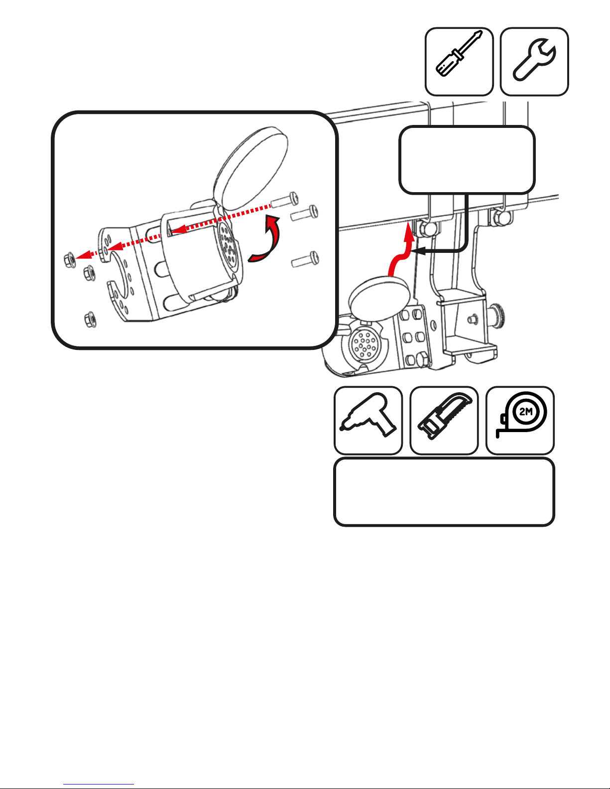
EXTRA CARE
Ensure cable is directed
to tting to make
bumper re-t easier.
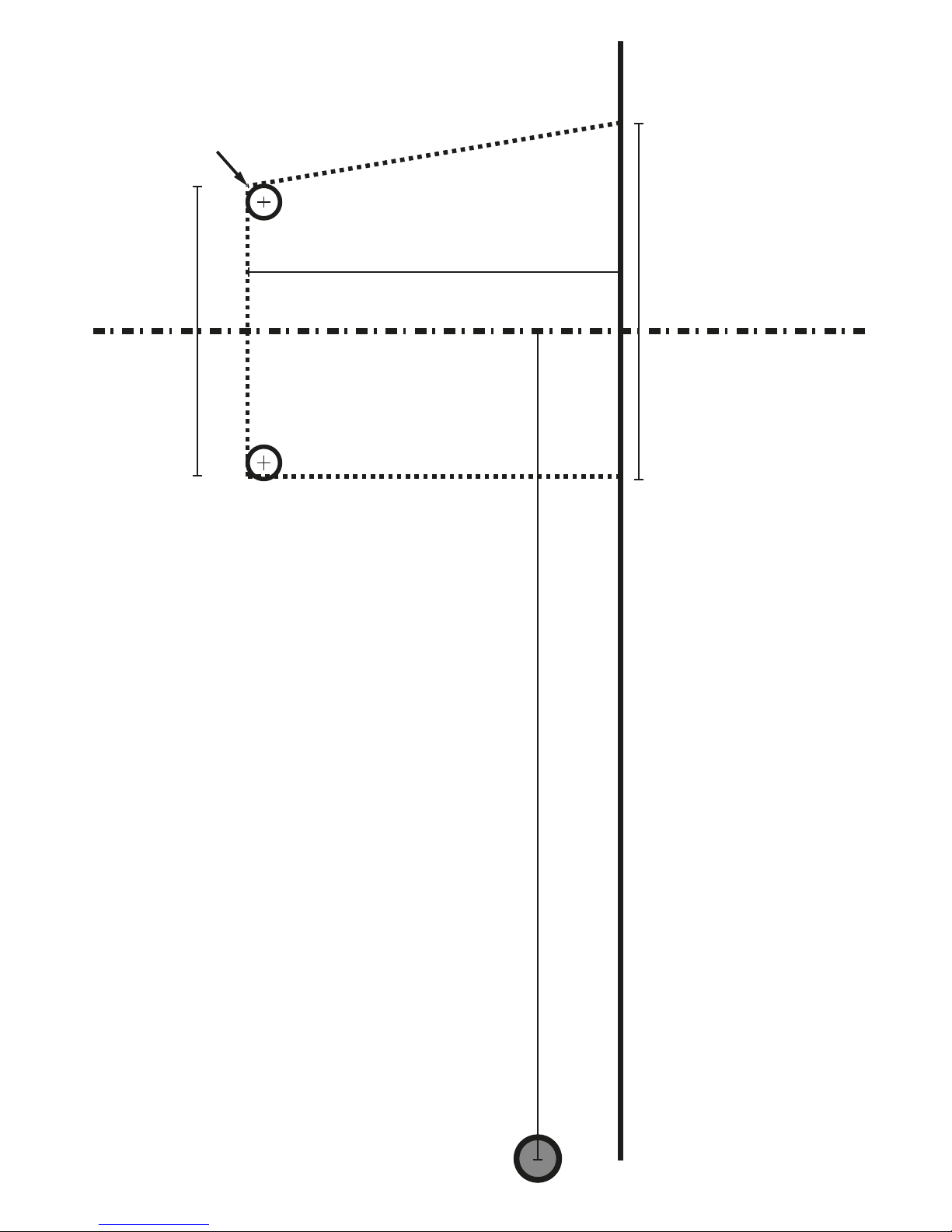
Step 9. Bumper Cut
Using the stencil provided and the step by step
guide to cut the vehicle bumper.
a) Orientate the bumper so as not to rest it on its
painted surfaces.
b) Place the stencil on the internal of the bumper.
It should be aligned with the bottom edge of the
bumper and a small hole found around 200mm
o centre.
c) It is recommended to drill holes in the marked
positions to allow turning of the saw blade when
cutting.
d) With holes drilled cut the bumper along the
cut lines outlined.
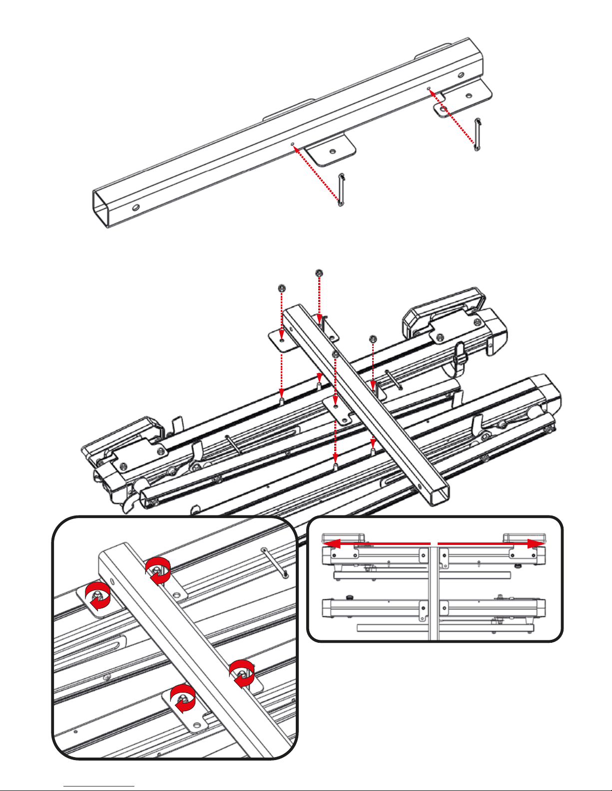
Step 10. Re-Fit Bumper
Re-t the bumper to the rear of the vehicle, ensure the
TEK kit cable is positioned correctly alongside the
tting and the tting is aligned with the bumper cut.
Check: Take extra care to ensure all tting are retted.
correctly and all clips replaced.
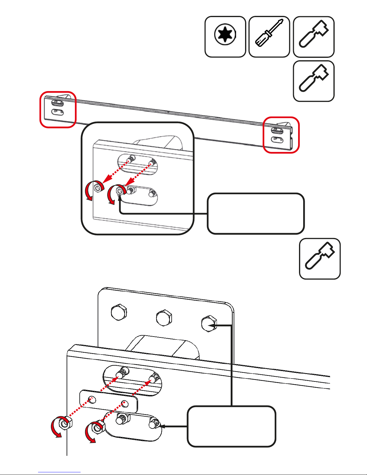
Step 8. Fix 13 Pin Connector
Mount the 13 Pin connector to the TEK Kits Bracket.
Ensure the orientation of the 13 pin connector matches
the illustration below with the cable directed towards
the tting.
CUTTING TIPS
We recommend rst drilling holes in
the marked positions to allow turning
of the saw blade in the corners.
Drill Saw Tape Measure
Spanner
Cross-Head
Screwdriver
10mm