Avago ADNK-5703 Guide

ADNK-5703
Optical Mouse Designer’s Kit
Design Guide
Introduction
The Universal Serial Bus (USB) is an industry standard
serial interface between a computer and peripherals such
as a mouse, joystick, keyboard, etc. This design guide
describes how a cost-eective USB optical mouse can
be built using the Avago Technologies ADNS-5700-XXXX
optical sensor. The document starts with the basic opera-
tions of a computer mouse peripheral followed by an in-
troduction to the Avago Technologies ADNS-5700-XXXX
Optical Navigation Sensor. A schematic of the ADNS-5700-
XXXX optical sensor and buttons of a standard mouse can
be found in Appendix A. The ADNS-5700-XXXX data sheet
is available from the AvagoTechnologies web site at www.
avagotech.com. USB documentation can be found at the
USB Implementers Forum web site at www.usb.org.
The ADNS-5700 sensor along with the ADNS-5100
round lens, ADNS-5100-001 trim lens or ADNS-5100-
002 truncated round lens, ADNS-5200 clip and HLMP-
ED80-XX000 LED form a complete and compact mouse
tracking system. There are no moving parts, which means
high reliability and less maintenance for the end user.
In addition, precision optical alignment is not required,
facilitating high volume assembly.
Optical Mouse Basics
The optical mouse measures changes in position by
optically acquiring sequential surface images (frames), and
mathematically determining the direction and magnitude
of movement. The Z-wheel movement is done in the
traditional method by decoding the quadrature signal
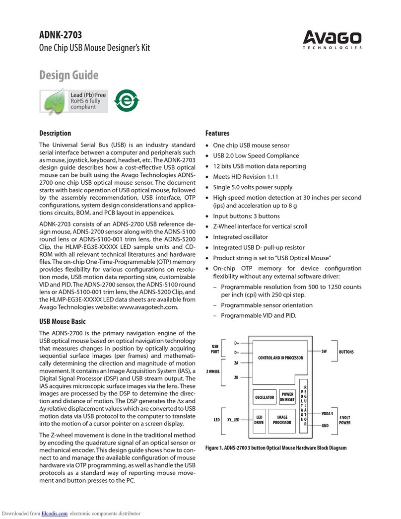
generated by optical sensors. This design guide shows
how to connect to and manage a standard conguration
of mouse hardware, as well as handle the USB protocols as
a standard way of reporting mouse movement and button
presses to the PC.
ZB
ZA
IMAGE
PROCESSOR
Z WHEEL
POWER
ON
RESET
V
O
L
T
A
G
E
R
E
G
U
L
A
T
O
R
LGND
XY_LED
LED
DRIVE
OSCILLATOR
OSCILLATOR
LED
OSC_IN
OSC_OUT
VOLTAGE
REFERENCE
D
D +
USB
PORT
5 VOLT
POWER
Vdd3
GND
Vdd5
BUTTONS
CONTROL AND
I/O PROCESSOR
GND
TL/B4
B3
B2
B1
TR/B5
ZLED
Figure 1. ADNS-5700-XXXX 3 button Optical Mouse Hardware Block Diagram
Lead (Pb) Free
RoHS 6 fully
compliant
RoHS 6 fully compliant options available;
-xxxE denotes alead-free product

2
Optical Sensor
Avago Technologies’s ADNS-5700-XXXX optical sensor is
used in this reference design as the primary navigation
engine. This Optical Navigation Technology contains an
Image Acquisition System, a Digital Signal Processor and
USB stream output.
The IAS acquires microscopic surface images via the lens
and illumination system provided by the ADNS-5100
round lens, ADNS-5100-001 trim lens or ADNS-5100-002
truncated lens, ADNS-5200 clip and HLMP-ED80-XX00
LED. These images are processed by the DSP to determine
the direction and distance of motion. The DSP generates
the 'x and 'y relative displacement values which are
converted to USB motion data.
Mouse Optics
The motion of Z-wheel is detected using the traditional
method by decoding the quadrature signal generated by
optical sensors.
For mechanical Z-wheels the following must be imple-
mented.
1. Use a rotary switch equivalent to the Panasonic part
EVQVX at http://industrial.panasonic.com/www-data/
pdf/ATC0000/ATC0000CE20.pdf (The key point is stable
“A”switch state in all detent positions).
2. Solder the rotary switch into the PCB such that the
common pin is closest to the cable end of the mouse.
(Metal plate faces to left)
3. Connect the “A” terminal of the rotary switch to “ZA”
and the “B”terminal to “ZB”. ZA MUST be connected to
“Signal A” in Figure 20 where the z-wheel detents are
mechanically stable.
As shown in Figure 2 below, traveling along the quadra-
ture signal to the right produces a unique set of state tran-
sitions, and traveling to the left produces another set of
unique state transitions.
Figure 2. Optics Quadrature Signal Generation
Mouse Buttons
Mouse buttons are connected as standard switches. These
switches are pulled up by the pull up resistors inside the
sensor. When the user presses a button, the switch will be
closed and the pin will be pulled LOW to GND. A LOW state
at the pin is interpreted as the button being pressed. A
HIGH state is interpreted as the button has been released
or the button is not being pressed. Normally the switches
are debounced in rmware for 9-17ms. In this reference
design there are three switches: left, Z-wheel and right.
Some details on ADNK-5703
The ADNK-5703 reference design mouse unit allows
users to evaluate the performance of the Optical Tracking
Engine (sensor, lens, Led assembly clip, Led) over a USB
protocol. The optical mouse uses the ADNS-5700-H4MB.
This kit also enables users to understand the recommend-
ed mechanical assembly. (See Appendix C and D)
System Requirements
PCs using Windows£2003/ Windows£XP/ Windows£
Vista with standard 3-button USB mouse driver loaded.
Functionality
3-button, mechanical scroll wheel mouse.
Operating (For USB Mode)
Hot pluggable with USB port. The PC does not need to be
powered o when plugging or unplugging the evaluation
mouse.
3
To Disassemble the ADNK-5703 Unit
The ADNK-5703 comprises of the plastic mouse casing,
printed circuit board (PCB), lens, buttons, and USB cable.
(See Figure 3) Unscrewing the one screw located at the
base of the unit can open the ADNK-5703 unit. Lifting and
pulling the PCB out of the base plate can further disas-
semble the mouse unit.
Caution: The lens is not permanently attached to the sensor and will
drop out of the assembly.
Figure 3. Exploded view drawing of optical tracking engine with ADNS-5700-
XXXX optical mouse sensor.
While reassembling the components, please make sure
that the Z height (Distance from lens reference plane to
surface) is valid. The Z-height is from 2.3 to 2.5mm with a
nominal of 2.4mm. Refer to Figure 4.
Sensor
LENS
Z
OBJECT SURFACE
Figure 4. Distance from lens reference plane to surface
Regulatory Requirements
xPasses FCC B and worldwide analogous emission limits
when assembled into a mouse with unshielded cable
and following Avago Technologies recommendations.
xPassesEN61000-4-4/IEC801-4EFTtestswhenassembled
into a mouse with shielded cable and following Avago
Technologies recommendations.
xUL ammability level UL94 V-0.
xProvides sucient ESD creepage/clearance distance
to avoid discharge up to 15kV when assembled with
round lens into a mouse according to usage instructions
above.
Sensor
The sensor technical information is contained in the
ADNS-5700-XXXX Data Sheet.
Lens
The lens technical information is contained in the ADNS-
5100 Data Sheet. The ange on the standard ADNS-5100
lens is for ESD protection.
LED Assembly Clip
The information on the assembly clip is contained in the
ADNS-5200 Data Sheet.
LED
The LED technical information is contained in the HLMP-
ED80-XX000 Data.
Base Plate Feature – 3D Model IGES Files
The IGES le on the CD-ROM provides recommended
base plate molding features to ensure optical alignment.
This includes PCB assembly diagrams like solder xture in
assembly and exploded view, as well as solder plate. See
Appendix D for details.
Reference Design Documentation – Gerber File
The Gerber File presents detailed schematics used in
ADNK-5703 in PCB layout form. See Appendix C for more
details.
Overall circuit
A schematic of the overall circuit is shown in Appendix A
of this document. Appendix B lists the bill of materials.
LED Clip
HLMP-ED80
ADNS-5700-XXXX
(sensor)
Customer
Supplied PCB
Lens (Full
Flanged
Shown)
Customer Supplied
Base Plate with
recommended
features per IGES
3D Model

4
USB Interface
All USB Human Interface Device (HID) class applications
follow the same USB start-up procedure. The procedure is
as follows
1. Device Plug-in
When a USB device is rst connected to the bus, it is
powered and running rmware, but communications
on the USB remain non-functional until the host has
issued a USB bus reset.
2. Bus Reset
The pull-up resistor on D– noties the hub that a device
has just been connected. The host recognizes the
presence of a new USB device and initiates a bus reset
to that device.
USB Jumper Table
Below is the USB jumper table for ADNS-5700-XXXX sensor for both 3 button and 5 button USB mouse. Both mouse type
will have dierent VID and PID strings. Also note the connections for OPT0 and OPT1.
Part Number Description
Resolution
(cpi) Buttons Tilt Wheel Z-Wheel
Sensor
Position VID PID
Mfg
String Product String
ADNS-5700-H3MB Standard 3
buttons
1000 3 No Mechanical 0° 0x192F 0x0416 Null USB Optical
Mouse
ADNS-5700-H3PB Standard 3
buttons
1000 3 No Optical 0° 0x192F 0x0416 Null USB Optical
Mouse
ADNS-5700-H4MB Standard 3
buttons
1000 3 TW Mechanical 0° 0x192F 0x0416 Null USB Optical
Mouse
ADNS-5700-H4PB Standard 3
buttons
1000 3 TW Optical 0° 0x192F 0x0416 Null USB Optical
Mouse
ADNS-5700-H5MD Standard 5
buttons
1000 5 No Mechanical 0° 0x192F 0x0616 Null USB Optical
Mouse
ADNS-5700-H5PD Standard 5
buttons
1000 5 No Optical 0° 0x192F 0x0616 Null USB Optical
Mouse
ADNS-5700-H3NB Standard 3
buttons
1000 3 No Mechanical 270° 0x192F 0x0416 Null USB Optical
Mouse
ADNS-5700-H3QB Standard 3
buttons
1000 3 No Optical 270° 0x192F 0x0416 Null USB Optical
Mouse
ADNS-5700-H4NB Standard 3
buttons
1000 3 TW Mechanical 270° 0x192F 0x0416 Null USB Optical
Mouse
ADNS-5700-H4QB Standard 3
buttons
1000 3 TW Optical 270° 0x192F 0x0416 Null USB Optical
Mouse
ADNS-5700-H5ND Standard 5
buttons
1000 5 No Mechanical 270° 0x192F 0x0616 Null USB Optical
Mouse
ADNS-5700-H5QD Standard 5
buttons
1000 5 No Optical 270° 0x192F 0x0616 Null USB Optical
Mouse
3. Enumeration
The host initiates SETUP transactions that reveal
general and device specic information about the
mouse. When the description is received, the host
assigns a new and unique USB address to the mouse.
The mouse begins responding to communication with
the newly assigned address, while the host continues
to ask for information about the device description,
conguration description and HID report description.
Using the information returned from the mouse,
the host now knows the number of data endpoints
supported by the mouse (2). At this point, the process
of enumeration is completed.

5
Appendix A: Schematic Diagram of the Overall Circuit
A1 Schematic for main board circuit using Avago Technologies ADNS-5700-H4MB optical mouse
A2 Button schematic and connection diagram
A3 Z-encoder schematic and connection diagram
1
2
3
4
5
6
J1
PIN HEADER 2MM6P/S
B5
B4
1
2SW7
12 SW6
Connect to PCB1
1
2SW9
12 SW8
VCC5
COM 3
B2
A1
Z1
Z-ENCORDER
1P1
ZA
ZB
1P2
1P3
Jump wire to PCB1
VCC5
VCC5
ZB
ZA
VCC
1
2
3
4
5
H1
HWFL 5Way
Shield
R
B
G
W
B
VCC5
COM 3
B2
A1
Z1
Z-ENCORDER
MiddleClick
Right Click
Left Click
13
2
SW1
13
2
SW2
1
2
3
X1
24MHZ
D1
HLMP-ED80
R1
59R
VCC5
LEDBin
C1
100nF C6
3.3uF/16V
3.3V
GND2
C3
100nF
C5
3.3uF/16V
GND3
C2
100nF
C4
4.7uF/16V
GND3
VCC5
R2
1k5
VCC5
GND3
GND2
D+
1
D-
2
ZA
3
ZB
4
LED_GND 5
XY_LED6
VDD5 7
GND
8
REG0
9
VDD3 10
TL
12
TR
13
GND 13
OSC_IN14
OSC_OUT15
B3 16
B2 17
B118
U1
ADNS-5700-H4MB
PICNotes:
Use through holes for USB wires
3.3V
12
SW3
12
SW4
12
SW5
TILT LEFT
TILT RIGHT
REG0
D+
D-
ZA
ZB
TL
TR
XY_LED
OSC_IN
OSC_OUT
B1
B2
B3
R3 22R
R4 22R
C10 C11
VDD5
ZB
ZA
GND2
VSS
D+
D-

6
Appendix B: Bill of Materials for Components Shown on schematic
Main Board
No Description Value Qty Designator
1 Resistor 22R 1% 2 R3.R4
2 Resistor 59R 1% 1 R1
3 Resistor 1k5 1% 1 R2
4 Capacitor Ceramic 100nF 3 C1.C2.C3
5 Capacitor Electrolytic 3.3uF, 16V 2
6 Capacitor Electrolytic 4.7uF, 16V 1
7 Capacitor Tantalum 10uF, 10V 2 C15.C16
8 IC Sensor A5700 1
9 Crystal - tCSALS24M0X53-B0 24Mhz 1
10 Connector – PCB Socket Straight 6 Way, S. Row 1
11 Cable – USB 1 meter 1
12 Jumper Wire
13 LED Clip ADNS-5200 1
14 Sensor LED HLMP-E80 1
15 Switch – Micro OMRON 3 Way 2
16 Switch – Push Button – 2
Button Board
No Description Color / Value Qty Designator
1 Connector – Pin Header Straight 6 Way S.Row 1 J1
2 Swtich – Push Button – 2 SW6.SW7
3 Switch – Push Button Tactile – 2 SW8.SW9
Z Encoder Board
No Description Color / Value Qty Designator
1 Z Encoder 3 Way 1 Z1

7
Appendix C: PCB Layout
Figure C1. PCB Schematic (Bottom Layer) Figure C2. PCB Schematic (Top Overlay)
90 (mm)
52.16 (mm)
90 (mm)
52.16 (mm)

For product information anda complete list ofdistributors, please go to our website: www.avagotech.com
Avago, Avago Technologies, andthe A logo are trademarks ofAvago Technologies in the UnitedStates andother countries.
Data subject to change. Copyright © 2005-2010 AvagoTechnologies. All rights reserved.
AV02-1738EN -June 8, 2010
Appendix D: Kit Components
The designer’s kit contains components as follows:
Part Number Description Name Quantity
ADNK-5703 Reference Design Mouse Reference Design Unit 1
ADNS-5700-XXXX Optical Mouse Sensor Sensor 5
ADNS-5100 Round Lens Plate Lens 5
ADNS-5100-001 Trim Lens Plate Lens 5
ADNS-5100-002 Truncated Round Lens Plate Lens 5
ADNS-5200 LED Assembly Clip LED Clip 5
HLMP-ED80-XX000 LED LED 5
ADNK-5703
CD
Includes Documentation and Support Files for ADNK-5703
Documentation
a. ADNS-5700-XXXX Optical Mouse Data Sheet
b. ADNS-5100 Round Lens Data Sheet/ADNS-5100-001 Trim Lens Data
c. ADNS-5100-001 Truncated Round Lens Data Sheet
d. ADNS-5200 LED Assembly Clip Data Sheet
e. HLMP-ED80-XX000 LED Data Sheet
Hardware Support Files
ADNK-5703 BOM List
b. ADNK-5703 Schematic
c. 3D Model IGES Files
d. Gerber File
1
Table of contents
Other Avago Mouse manuals

Avago
Avago ADNK-6003-SP01 Guide

Avago
Avago ADNK-5033-CSBT Guide

Avago
Avago ADNK-2703 Guide

Avago
Avago ADNK-3043-ND24 Guide

Avago
Avago ADNK-5003 Guide

Avago
Avago ADNK-6013-SP01 Guide

Avago
Avago ADNK-2083-ND24 User manual

Avago
Avago LaserStream ADNK-6093-SP11 Guide

Avago
Avago ADNK-5023-HTP2 Guide

Avago
Avago ADNK-3083 Guide