Avago ADNK-5033-CSBT Guide

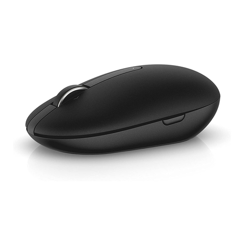
ADNK-5033-CSBT
Bluetooth Optical Mouse Designer’s Kit
Design Guide
Introduction
This design guide describes the design of a Bluetooth
optical mouse using the Avago Technologies small
form factor power saving ADNS-5030 optical navigation
sensor and Cambridge Silicon Radio (CSR) BlueCore4-
External Bluetooth chip. The receiver dongle is a
standard commercially-available Bluetooth module
with another BlueCore4-External chip. The document
starts with the basic operations of a computer mouse
peripheral followed by an introduction to the Avago
Technologies ADNS-5030 Optical Navigation Sensor
and the CSR’s BlueCore4-External Bluetooth chip. The
description of how to program the mouse firmware is
in the BlueICE section of the document, followed by
how to connect the mouse to the computer . All
schematic diagrams of the BlueCore4-External chip to
the ADNS-5030 optical sensor and buttons of a
standard mouse can be found in Appendix A. The
ADNS-5030 data sheet is available from the Avago
Technologies website at: http://www.avagotech.com.
The BlueCore4-External Bluetooth Flash chip
datasheets are available from the CSR website at
www.csr.com. USB documentation can be found at the
USB Implementers Forum web site at www.usb.org.
Features of ADNK-5033-CSBT
••
••
•Windows® 98SE, Windows 2000, and Windows XP
compatibility
••
••
•USB 2.0 low-speed compliance
••
••
•Bluetooth® v2.0+EDR system (fully qualified)
••
••
•User identity code to avoid conflict with other
devices
••
••
•High reliability
••
••
•Precise wireless optical navigation technology
••
••
•No mechanical moving parts
••
••
•Smooth surface navigation
••
••
•Auto mouse sensor frame speed
••
••
•Accurate motion up to 14 ips
••
••
•500/1000 cpi resolution selection
••
••
•Self-adjusting power saving modes for longer
battery life
••
••
•Minimal number of passive components
••
••
•Enhanced Data Rate (EDR) compliant for both 2Mbps
and 3Mbps modulation modes
••
••
•Full speed Bluetooth operation with full Piconet
support
••
••
•Scatternet support

2
Reference Design Overview
The image-based optical mouse sensor takes snapshots
of the surface it is navigating on. It measures changes
in position by comparing the sequential images
(frames) and mathematically determines the direction
and magnitude of movement. The traditional dual-
channel encoder generates the quadrature Z-wheel
movement signals. This design guide illustrates the
hardware connection of a LED-based optical mouse
with standard configuration; as well as the firmware
management and the handling of the USB HID and
Bluetooth protocols. USB HID protocol provides a
standard way of reporting mouse movement and
button presses to the PC. The Windows HID with
Bluetooth driver interprets the data and performs the
cursor movements and mouse clicks.
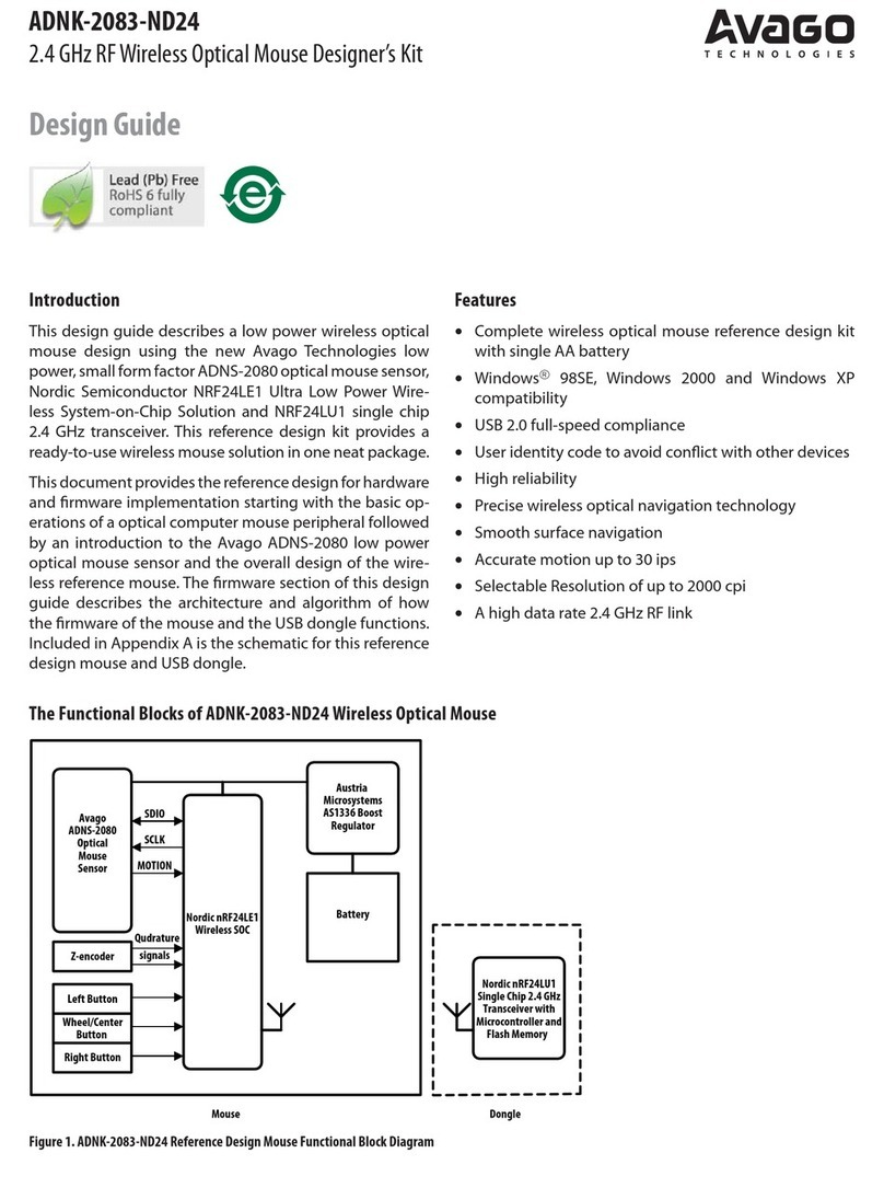
The functional block diagram of the reference design
mouse is shown in Figure 1. The optical sensor detects
the Y and X movements. The mechanical quadrature
encoder provides the Z-wheel movement. Each of the
button switches is normally pulled up and provides a
Ground when pressed. The reference design mouse is
powered up by two regular AA Alkaline batteries in
series.
Theory of Operation
Optical Navigation Technology
The heart of the ADNS-5030 navigation sensor is a
CMOS image array. An LED and an optical system
illuminate the surface that the ADNS-5030 is navigating
on. The texture of the surface casts bright and dark
spots forming distinct images as the sensor is moved
across the surface. A Digital Signal Processing (DSP)
engine and its built-in algorithm evaluate these images
and determine the magnitude and direction of the
movement. The motion data is made available in the
Delta_X and Delta_Y registers for the system controller
to retrieve. An optimized power saving topology is
implemented within the ADNS-5030 navigation engine.
Motion bit is available to indicate if motion occurred.
As long as there is no motion the system can remain in
Sleep mode allowing maximum battery power saving.
Based on the last detected motion the ADNS-5030
navigation engine enters various power saving modes
when no new motion occurs. These power saving
features make the ADNS-5030 ideally for wireless
applications.
Figure 2. Illustration of Optical Navigation technology
Figure 1. ADNK-5033-CSBT Reference Design Mouse functional Block Diagram
Sensor LED Clip
PCB
Surface
Base Plate
Lens/Light Pipe
Lens
Image
Array
LED
Lens
Surface
Shadow pattern

3
Mechanical Z-Wheel
The motion of Z-wheel is detected using the traditional
method by decoding the quadrature signal generated
by the mechanical encoder. The Z-pinwheel is
connected to the Z-encoder through its shaft. The
rotational movement of the shaft is decoded into on
and off levels in a quadrature output pattern. Every
change in the Z-encoder outputs represents a count
of mouse movement. Comparing the last state of the
Z-encoder to the current state derives direction
information. As shown in Figure 2, traveling in
clockwise direction produces a unique set of state
transitions, and traveling in counter clockwise direction
produces another set of unique state transitions. In this
reference design, only the motion at the Z-wheel is
detected using this method.
Mouse Buttons
Mouse buttons are connected as standard switches to
the BlueCore4-External Bluetooth chip which is
designed to autonomously sample button status with
the programmable hardware de-bounce and ghost key/
glitch filtering and store them into buffer registers
without the need for the host microcontroller to
intervene. In this reference design there are three
switches: left, middle, and right. The mouse buttons
are configured with PS key ‘HIDIO mouse button’ PIO
assignments.
Figure 2. Mechanical Z-Wheel Output Signal Generation
Hardware Implementation
Optical Navigation Sensor
Avago Technologies’ ADNS-5030 optical sensor is used
in this reference design as the primary navigation
engine. This Optical Navigation Technology contains
an Image Acquisition System, a Digital Signal Processor,
and a four-wire serial port. The BlueCore4-External
Module periodically reads the ADNS-5030’s Delta_X
and Delta_Y registers to obtain any horizontal and
vertical motion information happening as a result of
the mouse being moved.
This motion information will be reported to the PC to
update the position of the cursor. The advantages of
using the ADNS-5030 optical sensor are the efficient
power management, high tracking accuracy, and
flexibility of programming the optical sensor via the
SPI port.
The system controller reads the motion information
and reports it to the PC to update the cursor position.
The advantages of using the ADNS-5030 optical sensor
are optimized power management, good tracking
accuracy, and efficient communications with the optical
sensor via the full duplex SPI port.
To learn more about sensor’s technical information,
please visit the Avago Technologies web site at http://
www.avagotech.com.
CSR BlueCore4 External
BlueCore™ refers to CSR’s single-chip microcontroller
which provides solution for Bluetooth® applications. In
this reference design, CSR BlueCore4 External is used.
BlueCore4 is the market leading EDR (enhanced data
rate) v2.0 compliant solution.

4
Special Features for BlueCore4-External Flash Module
(on mouse):
••
••
•Enhanced Data Rate (EDR) compliant for both 2Mbps
and 3Mbps modulation modes
••
••
•Single-chip solution integrating radio, baseband,
microcontroller
••
••
•External Flash memory interface (8Mbits)
••
••
•Bluetooth® v2.0+EDR system (fully qualified)
••
••
•Full speed Bluetooth operation with full Piconet
support
••
••
•Scatternet support
••
••
•1.8V core, 1.8 to 3.6V I/O
••
••
•Low power 1.8V operation (integrated 1.8V
regulator)
••
••
•Minimum external components
••
••
•UART and SPI ports
••
••
•8x8 or 6x6mm VFBGA packaging
Special Features for BlueCore4-External Bluetooth
Dongle:
••
••
•Highly-economical
••
••
•Commercially available, off-the-shelf solution
••
••
•Enhanced Data Rate (EDR) compliant for both 2Mbps
and 3Mbps modulation modes
••
••
•Single-chip solution integrating radio, baseband,
microcontroller
••
••
•External Flash memory interface (8Mbits)
••
••
•Bluetooth® v2.0+EDR system (fully qualified)
••
••
•Full speed Bluetooth operation with full Piconet
support
••
••
•Scatternet support
••
••
•Support for 802.11 coexistence
••
••
•1.8V core, 1.8 to 3.6V I/O
••
••
•Low power 1.8V operation (integrated 1.8V
regulator)
••
••
•Minimum external components
••
••
•8x8 or 6x6mm VFBGA packaging
Bluetooth Technology overview
The following description of Bluetooth technology is
from the official Bluetooth Special Interest Group (SIG)
website:
How Bluetooth Technology Works
Bluetooth wireless technology is a short-range
communications system intended to replace the cables
connecting portable and/or fixed electronic devices.
The key features of Bluetooth wireless technology are
robustness, low power, and low cost. Many features of
the core specification are optional, allowing product
differentiation.
The Bluetooth core system consists of an RF transceiver,
baseband, and protocol stack. The system offers
services that enable the connection of devices and the
exchange of a variety of data classes between these
devices.
Overview of Operation
The Bluetooth RF (physical layer) operates in the
unlicensed ISM band at 2.4GHz. The system employs a
frequency hop transceiver to combat interference and
fading, and provides many FHSS carriers. RF operation
uses a shaped, binary frequency modulation to
minimize transceiver complexity. The symbol
rate is 1 Megasymbol per second (Msps) supporting
the bit rate of 1 Megabit per second (Mbps) or, with
Enhanced Data Rate, a gross air bit rate of 2 or 3Mb/s.
These modes are known as Basic Rate and Enhanced
Data Rate respectively.
During typical operation, a physical radio channel is
shared by a group of devices that are synchronized to
a common clock and frequency hopping pattern. One
device provides the synchronization reference and is
known as the master. All other devices are known as
slaves. A group of devices synchronized in this fashion
form a piconet. This is the fundamental form of
communication for Bluetooth wireless technology.
Devices in a piconet use a specific frequency hopping
pattern which is algorithmically determined by certain
fields in the Bluetooth specification address and clock
of the master. The basic hopping pattern is a pseudo-
random ordering of the 79 frequencies in the ISM band.
The hopping pattern may be adapted to exclude a
portion of the frequencies that are used by interfering
devices. The adaptive hopping technique improves
Bluetooth technology co-existence with static (non-
hopping) ISM systems when these are co-located.
The physical channel is sub-divided into time units
known as slots. Data is transmitted between Bluetooth

5
enabled devices in packets that are positioned in these
slots. When circumstances permit, a number of
consecutive slots may be allocated to a single packet.
Frequency hopping takes place between the
transmission or reception of packets. Bluetooth
technology provides the effect of full duplex
transmission through the use of a time-division duplex
(TDD) scheme.
Above the physical channel there is a layering of links
and channels and associated control protocols. The
hierarchy of channels and links from the physical
channel upwards is physical channel, physical link,
logical transport, logical link and L2CAP channel.
Within a physical channel, a physical link is formed
between any two devices that transmit packets in
either direction between them. In a piconet physical
channel there are restrictions on which devices may
form a physical link. There is a physical link between
each slave and the master. Physical links are not formed
directly between the slaves in a piconet.
The physical link is used as a transport for one or more
logical links that support unicast synchronous,
asynchronous and isochronous traffic, and broadcast
traffic. Traffic on logical links is multiplexed onto the
physical link by occupying slots assigned by a
scheduling function in the resource manager.
A control protocol for the baseband and physical layers
is carried over logical links in addition to user data.
This is the link manager protocol (LMP). Devices that
are active in a piconet have a default asynchronous
connection-oriented logical transport that is used to
transport the LMP protocol signaling. For historical
reasons this is known as the ACL logical transport. The
default ACL logical transport is the one that is created
whenever a device joins a piconet. Additional logical
transports may be created to transport synchronous
data streams when this is required.
The link manager function uses LMP to control the
operation of devices in the piconet and provide
services to manage the lower architectural layers (radio
layer and baseband layer). The LMP protocol is only
carried on the default ACL logical transport and the
default broadcast logical transport.
Above the baseband layer the L2CAP layer provides a
channel-based abstraction to applications and services.
It carries out segmentation and reassembly of
application data and multiplexing and de-multiplexing
of multiple channels over a shared logical link. L2CAP
has a protocol control channel that is carried over the
default ACL logical transport. Application data
submitted to the L2CAP protocol may be carried on
any logical link that supports the L2CAP protocol.
BlueICE Overview
BlueICE is a collection of software and firmware
components designed to enable the rapid
development of a BlueCore based Bluetooth desktop
set consisting of a keyboard, mouse and host module.
While not required, using BlueICE for all three
components of the desktop allows advanced features
of the software (such as Auto-Connect) to be utilized.
The user interacts with the BlueICE software through
dedicated pushbuttons on the devices and host
module.
The BlueCore devices indicate status through PIOs
configured as outputs from BlueCore. Normally these
PIOs are used to drive LEDs to indicate status to the
user.
User-Supplied Hardware Components
Human Interface Device(s)
BlueICE device firmware is intended for use on a
BlueCore4-External based Bluetooth HID (firmware for
other BlueCore variants is available on request from
CSR). A Casira with BlueCore4-External module and a
product prototype is recommended for early device
development.
Device Firmware
BlueICE device firmware for use on BlueCore4-External
is supplied. The firmware can be used in any of the
following BlueCore-based Bluetooth HIDs:
••
••
•Mouse (BlueCore interfacing to Avago optical sensor.
See Error! Reference source not found.for supported
sensors)
The firmware is configured by PS Keys to specify the
type of device. Many other configuration options are
also available. See section 0 for full details.
The firmware supplied is suitable for use while
developing and prototyping a Bluetooth HID. It offers
the flexibility necessary to ease PCB design. It is,
however, not production ready firmware, partly since
some customer specific options are hard coded in the
firmware. Contact CSR to obtain product specific
release firmware.
6
Getting Started
Firmware must be programmed into a BlueCore chip
through the SPI interface. BlueICE solutions currently
use external rewriteable flash memory. The SPI
Interface is also used to configure the behaviour of the
BlueICE application.
It is beyond the scope of this document to describe
how to provide SPI interface access to your design.
The instructions below describe how to use a Casira
Development Kit as the host module.
Programming Mouse Firmware into Flash Using
BlueFlash
Back up the firmware and settings currently loaded on
the Casira module as described in the Casira User
Guide.
Download the latest firmware files from the BlueICE
for access to this site). There are three important files
for each component of BlueICE - .xdv, .xpv and .psr.
Copy all three host module firmware files to a local
directory.
Install BlueSuite; this is also available from the BlueICE
section of www.csrsupport.com.
Connect the power cable to the Casira Development
Kit.
Connect the SPI cable between the Casira Development
Kit and the parallel port of your PC. This is the grey
ribbon cable supplied with the Casira Development
Kit.
Double click on BlueFlash in the BlueSuite directory to
start the CSR flash programming utility.
Configuring Mouse Firmware with PSTool
The PSTool PC application is used to do all the BlueICE
configuration. PSTool is part of the BlueSuite package
available for download from the CSR web site
(www.csr.com). See the BlueSuite documentation for
detailed instructions on using PSTool. The following
steps describe how to configure the mouse firmware
running on a Casira Development Kit.
1. Install BlueSuite; this is available from the CSR web
site
2. Connect the power cable to the Casira Development
Kit
3. Connect the SPI cable between the Casira
Development Kit and the parallel port of your PC.
This is the grey ribbon cable supplied with the Casira
Development Kit.
4. Start PSTool. A Choose Transport dialog box
appears:
Figure 0.3: Connecting to the Mouse with PSTool
Figure 0.1: The BlueFlash Application Dialog Box
Click on the Stop Processor button. Click on Flash Erase
button. Click on Erase Full chip.
Click on the Chose File button and browse to the
directory containing the firmware files.
Click on the .xpv file and press Open.
Figure 0.2: Ready to Download Firmware with BlueFlash
Press the Download button to download the firmware.
When this has finished press the Start Processor button
to complete the operation.

7
Figure 0.4: The PSTool Application
5. Select SPI BCCMD and tick Halt Chip on SPI access.
Select the correct printer port (usually LPT1).
6. You are now ready to start configuring your host
module firmware as described in section Error!
Reference source not found.
Downloading the Default PS Key Values
The release of the BlueICE firmware for the ADNK-5033-
CSBT is accompanied by a PS Key configuration file
containing known good PS Keys for the ADNK-5033-
CSBT. Downloading this file to the mouse sets all the
PS Keys to values that are known to work with the
BlueICE firmware.
When configuring a Casira Development Kit to use host
module firmware for the first time it is advisable to
download this file. Use the following steps to set up a
Casira module as a BlueICE host module with known
good PS Key values.
1. Program the host module firmware as described in
section 0.
2. Start PSTool
3. Click on Merge… from the File menu
4. Browse to the .psr file supplied with the host module
firmware release
5. Click on Open
6. Reset the BlueCore4-External chip by cycling the
power.
The chip is now configured to run in the default mode
using the PIO assignments suitable for the CSR Casira
Development Kit.

8
Setting Up the Device
The device firmware is configured by PS Keys, which
are accessible with the CSR host software application,
PSTool.
Class of Device
Tells the firmware what type of device it is running on.
Supported devices are keyboard, mouse or combo
device (keyboard with mouse functionality). The PS Key
should be set to the HID minor class of the device.
Currently supported minor classes are:
Class of Device Class of Device Code
Keyboard 0x0040
Mouse 0x0080
Combo (keyboard and mouse) 0x00C0
PS Key Description Value
PSKEY_USR2 Class of device 0x0040, 0x0080 or 0x00C0
Sensor Interface
If class of device is set to mouse, then the sensor
interface used is set with this PS Key. Mouse sensors
supported are: UART, Avago 1st generation (3 wire
serial) and Avago 2nd generation (4 wire serial).
Additional sensors will be supported in the future. If
UART is selected as the sensor interface, then a co-
processor is required to interface to the sensor. The
co-processor will need to send HID input reports to
BlueCore via the UART.
See Error! Reference source not found.for more
information about Avago mouse sensors and their
interfaces. In this document, ‘directly interfacing
BlueCore to an Avago sensor’ means BlueCore
controlling the mouse sensor via direct connections
between PIOs and the sensor pins, as opposed to an
external co-processor intervening.
Avago sensors used to be manufactured by Agilent,
and hence some of the PS Key names and descriptions
still reflect this.
PS Key Value Sensor Interface
PSKEY_USR3 1 Avago 1st generation
PSKEY_USR3 2 UART
PSKEY_USR3 5 Avago 2nd generation
Value Description
0x0000 This mask IO is unused.
0x0001 to 0x7FFF PIO mask - describes which
BlueCore PIOs are used for this mask
IO (one bit each for PIOs 0 to 14).
0x8000 Single bit which, when bitwise ORd
with the PIO mask, inverts the sense
of the IO (IOs are normally active
high. Setting this bit makes the IO
active low).
The following table shows how to configure a value
IO:
Value Description
0x0000 to 0x000F PIO - The PIO used for this IO.
0x0100 Single bit which, when bitwise ORd
with the PIO value, inverts the sense
of the IO. (IOs are normally active
high. Setting this bit makes the IO
active low).
Word Position IO Comments
0 Connection status Mask
1Capslock
2 Scroll lock
3Numlock
4 Bootmode
5Powerhold
6ConnectInput
7 Status modifier Modifier
8 Battery is charging Input
Programmable IO
PIOs are configurable input and output pins on
BlueCore. This section describes how to configure them
for a HID.
General IO
PSKEY_USR33 is used to configure the following IOs:
connection status, caps lock, scroll lock, num lock,
bootmode, power hold, connect button and battery is
charging. Each IO is configured by a single word in the
PS Key and in one of two ways: as a mask or value.
In addition to the IO configuration words, a word can
be described as a modifier. A modifier word is typically
used to modify the configuration of a specific IO. Each
one is described separately.
The following table shows how to configure a mask
IO:
The order of the configuration words in PSKEY_USR33
is as follows (the IO is described as a value and is an
output unless otherwise stated):

9
The status modifier is used to modify the way the
connection status is output by the device. If connection
status is non-zero, then a value of 1 in the status
modifier tells the firmware to use the AUX DAC as the
connection status output. This can be useful in a mouse
design where the number of available PIOs is limited.
If status modifier is not used, it must be set to 0xFFFF.
An example PSKEY_USR33 entry for a keyboard is as
follows:
8007 0100 0101 0102 0003 0109 000a ffff ffff
Here, connection status is indicated on PIOs 0, 1 and 2
(from the mask), which are active low.
Caps, Num and Scroll Lock are indicated on PIOs 0, 1
and 2 respectively, and are active low. Note that the
same PIOs are used for Caps, Num and Scroll Lock
indication as connection status indication.
Boot mode is indicated on PIO 3.
Power hold is indicated on PIO 9 and is active low.
This means in normal operation, this PIO is driven low.
When a battery critical level is reached, the PIO will
drive high. This can be used to indicate a low battery
condition, or to disable a power supply regulator on
the device if the battery voltage is dangerously low.
The connect button is attached to PIO 10. The connect
button is used to make the device discoverable.
The status modifier is unused, and hence does not
modify the connection status IO configuration.
PS Key Word Position Comments
PSKEY_HIDIO_BUTTON 0 PIO assignment for mouse button 1
PSKEY_HIDIO_BUTTON 1 PIO assignment for mouse button 2
PSKEY_HIDIO_BUTTON 2 PIO assignment for mouse button 3
PSKEY_HIDIO_BUTTON 3 PIO assignment for mouse button 4
PSKEY_HIDIO_BUTTON 4 PIO assignment for mouse button 5
PS Key Word Position Comments
PSKEY_HIDIO_WHEEL 0 PIO assignment for mouse wheel Quad A input
PSKEY_HIDIO_WHEEL 1 PIO assignment for mouse wheel Quad B input
PSKEY_HIDIO_WHEEL 2 PIO assignment for mouse wheel enable output.
Can be set to 0xFD to use RTS pin.
PS Key Value Comments
PSKEY_USR5 0x0000 (or 0x8000 for active low Wheel Enable) Denotes a full-quadrature wheel is being used
PSKEY_USR5 0x0001 (or 0x8001 for active low Wheel Enable) Denotes a half-quadrature type 1 wheel is being used
PSKEY_USR5 0x0002 (or 0x8002 for active low Wheel Enable) Denotes a half-quadrature type 2 wheel is being used
The battery is charging IO is unused. In this
configuration, the battery status report always indicates
that the device’s battery is not being charged. If this
IO is configured, then its PIO should be pulled high to
indicate that the device’s battery is being charged.
When the firmware is told the battery is charging, it
will not disconnect from its host after an idle timeout
and will respond to host requests for battery
information indicating that its battery is being charged.
Mouse Button IO
When the device is a mouse and BlueCore is directly
interfaced to an Avago sensor, additional IO setup is
required. This section describes how to configure the
mouse button IO in this case.
The mouse button and wheel setup is common to all
sensor configurations. The mouse buttons are
configured with PSKEY_HIDIO_BUTTON. It takes 5
words, which configure the PIOs for buttons 1 through
5. If the button is unused, its configuration word should
be set to 0x00FF.
As an example, PSKEY_HIDIO_BUTTON assignments of:
0002 0007 0004 00ff 00ff
would be used if the mouse button 1 was connected
to PIO[2]; button 2 connected to PIO[7]; button 3
connected to PIO[4]; with no other buttons connected
(a three-button mouse).

10
Mouse Wheel IO
When the device is a mouse and BlueCore is directly
interfaced to an Avago sensor, additional IO setup is
required. This section describes how to configure the
mouse wheel IO in this case.
The mouse wheel is configured with two PS Keys,
PSKEY_HIDIO_WHEEL and PSKEY_USR5.
PSKEY_HIDIO_WHEEL takes three words which
configure the PIOs to use for Quad A input, Quad B
input and the Wheel Enable output. It is also possible
to use the BlueCore RTS pin as Wheel Enable, freeing
up a PIO. In which case, the Wheel Enable configuration
word should be set to 0xFD.
PSKEY_USR5 is used to specify the type of mouse wheel
being used, and whether the Wheel Enable is active
high or low. A single word is used to specify the wheel
type. Setting the most significant bit of the word to 1
(i.e. by ORing with 0x8000) specifies that Wheel Enable
should be active low.
If it is not known which type of wheel is being used,
CSR recommends trying each of the above settings,
and settling on the one that gives the best wheel
performance.
PS Key Word Position Comments
PSKEY_HIDIO_AGILENT_SP2 0 PIO assignment for Avago 2nd generation interface SCLK line
PSKEY_HIDIO_AGILENT_SP2 1 PIO assignment for Avago 2nd generation interface MOSI line
PSKEY_HIDIO_AGILENT_SP2 2 PIO assignment for Avago 2nd generation interface MISO line
PSKEY_HIDIO_AGILENT_SP2 3 PIO assignment for Avago 2nd generation interface NCS line
PSKEY_HIDIO_AGILENT_SP2 4 PIO assignment for Avago 2nd generation interface MOT line
(set to 0xFF is unused)
PSKEY_HIDIO_AGILENT_SP2 5 PIO assignment for Avago 2nd generation interface STDWN line
(set to 0xFF if unused)
PS Key Value Comments
PSKEY_BAUDRATE 9.6kbaud to 3686.4kbaud Actual value in the PS Key is calculated as:
value = baud_rate * 0.004096
PSKEY_HOST_INTERFACE VM access to UART Allows the virtual machine access to the UART
PSKEY_DEEP_SLEEP_PIO_WAKE 0 to 15 PIO assignment for the UART flow control asynchronous
line input to BlueCore
PSKEY_HIDIO_UART 0 to 15 PIO assignment for the UART flow control synchronous
line input to BlueCore
Sensor Interface IO
When the device is a mouse and the sensor interface
selected is Avago 2nd generation, the sensor interface
itself needs to be configured. This involves setting
PSKEY_HIDIO_AGILENT_SP2 to specify the PIOs used
for the SCLK, MOSI, MISO, NCS, MOT (optional) and
STDWN (optional) lines.
UART as Sensor Interface
In order for deep sleep mode to be enabled on
BlueCore when the UART is used as the sensor
interface, flow control needs to be used. Flow control
is necessary to avoid HID report loss across the UART
when the BlueCore is in deep sleep. The flow control
scheme gives an indication to the co-processor when
BlueCore is awake and ready to receive HID reports
over the UART.
Successful UART flow control reduces power
consumption and latency in a device.
Details of the flow control scheme and report format
can be found in section <xxx not available yet>. This
section describes the necessary persistent store
configuration required for using the BlueCore UART as
the sensor interface.

11
PS Key Bit Position Within Single Word Comments
PSKEY_USR6 0 Inverts X data when set to 1
PSKEY_USR6 1 Inverts Y data when set to 1
PSKEY_USR6 2 Swaps X and Y data when set to 1
PS Key Value Comments
PSKEY_USR12 0x0000 Sets the sensor resolution to low
PSKEY_USR12 0x0001 - 0xFFFF, or no value Sets the sensor resolution to high
PS Key Word Position Comments
PSKEY_HIDIO_AVAGO_LASER_CONFIG 0 8 bit value to write to the Avago laser sensor's
LASER_CTRL0 register.
PSKEY_HIDIO_AVAGO_LASER_CONFIG 1 8 bit value to write to the Avago laser sensor's
LSRPWR_CFG0 register.
Avago Laser Sensor
When the device is a mouse, the sensor interface
selected is Avago 2nd generation and the sensor used
is an Avago 60x0 or 70x0, additional configuration is
required. Laser calibration is needed to comply with
Class 1 laser power regulations. Laser configuration is
achieved through
PSKEY_HIDIO_AVAGO_LASER_CONFIG. This PS Key
allows the user to write to the LASER_CTRL0 and
LSRPWR_CFG0 sensor registers according to the
following table. The firmware takes care of writing the
inverted values to LASER_CTRL1 and LSRPWR_CFG1
respectively.
For more information about Avago laser sensor
registers and calibrating the laser power see the
relevant Avago datasheet.
Avago Sensor Configuration
When the device is a mouse and the sensor interface
selected is Avago 1st generation or Avago 2nd
generation, additional configuration options are
available and may be required. These options are to
configure the (X,Y) translation of the motion data
acquired from the sensor and the resolution at which
the sensor reports motion.
(X,Y) translation can be modified by setting a single
word in PSKEY_USR6. The word is a bitfield of 3 bits,
specifying whether to invert either the X or Y data, or
to swap the X and Y data. The X,Y swap is performed
before inverting the X and/or Y data.
As an example, setting PSKEY_USR6 to 0005 swaps the
X and Y data, then inverts X.
The resolution at which the sensor reports motion can
be set with a single word in PSKEY_USR12. Setting this
word to zero denotes low resolution (400-500cpi), non-
zero denotes high resolution (800-1000cpi). With no
word in this PS Key, the resolution defaults to high.

12
Battery Monitoring
The BlueICE firmware can be setup to sample the
device’s battery voltage and convey a battery
percentage reading to the host via a vendor specific
HID feature report. This section details the
configuration necessary for battery monitoring.
Word Position in
PSKEY_USR35 Value Comments
0 0 => battery monitoring disabled
1 => AIO0
2 => AIO1
3 => VDD
4 => AIO2
5 => AIO3 (only on some chip variants)
6 => internal monitor (only on some chip variants)
The analogue source from which to
acquire the battery voltage reading. If 0,
the battery monitoring is disabled
(battery reading will not be
communicated to the host).
1 0 to 60 The battery voltage sampling period in
seconds. A value of 0 will sample the
battery voltage once, and only once,
while the firmware is booting.
2 0 to Vdd (mV) The voltage at the specified analogue
source (1) when the battery is at 100%.
3 0 to Vdd (mV) The voltage at the specified analogue
source when the battery is at 75%.
4 0 to Vdd (mV) The voltage at the specified analogue
source when the battery is at 50%.
5 0 to Vdd (mV) The voltage at the specified analogue
source when the battery is at 25%.
6 0 to Vdd (mV) The voltage at the specified analogue
source when the battery is at or below
the danger level (2).
7 0 to Vdd (mV) The voltage at the specified analogue
source when the battery is empty (3).
PSKEY_USR35 is used to setup battery monitoring and
takes the following parameters in successive words:
sampling source, sampling period, voltage at 100%,
voltage at 75%, voltage at 50%, voltage at 25%, danger
voltage (below which an indication is given that battery
is low) and voltage at empty.
Notes:
1. The voltage at the analogue source means, for example, the voltage presented at an AIO pin. This does not take into account any potential
divider or other circuitry external to the chip which may divide down the actual battery voltage.
2. Danger level means the voltage at which the firmware will indicate ‘low battery’.
3. The empty battery voltage level should be the minimum battery voltage at which the device can operate. Typically this would be the
minimum operating input voltage of the device’s voltage regulator(s) (scaled by any external potential divider, as noted above).

13
PIN Code (or Passcode)
A BlueICE device can be configured to have a fixed PIN
code or to have no fixed PIN code. If a fixed PIN code is
used, this will always be used during authentication. If
no fixed PIN code is used, some method of entering
the PIN code during authentication is required on the
device. On a keyboard, the number keys can be used
to enter the PIN code.
The PIN code is configured with PSKEY_USR36. The
first word specifies the length in bytes of the PIN code.
The subsequent words specify the PIN code with two
bytes packed into each word big-endian. The PIN code
bytes are specified as ASCII codes.
As an example, to give the device a fixed PIN code of
1234, PSKEY_USR36 would be:
0004 3132 3334
The BT HID specification recommended default is a PIN
code of 0000, and then PSKEY_USR36 would be:
0004 3030 3030
Device Identification
The BlueICE device presents a Device Identification SDP
record to its Bluetooth host. Several of the parameters
of the record are configurable via PS Keys. This section
describes the PS Keys to facilitate this.
Word Position in
PSKEY_USR36 Value Comments
0 0 to 16 The length of the PIN code. 0 is special and
denotes 'no PIN code'.
1 to 8 2 ASCII bytes packed into a word 'big-endian'. The high byte of a word comes first, followed
by the low byte.
PS Key Value Comments
PSKEY_USR30 0x0000 to 0xFFFF Device's PID.
Vendor ID and Source
The vendor ID (VID) of the manufacturer of the device
can be specified with PSKEY_USR29. The source of the
VID can be specified with PSKEY_USR32.
The VID source (the organisation that issued the VID)
can be specified with PSKEY_USR32. The format for
this key conforms to the Bluetooth Device ID
specification, namely a value of 0001 specifies a
Bluetooth SIG assigned VID, a value of 0002 specifies a
USB-IF assigned VID.
Product ID
The product ID of the device is intended to differentiate
between different products manufactured by the same
vendor, and can be specified with PSKEY_USR30.
Version
The device’s version identifies the release number for
a given product and vendor ID pair. The Bluetooth
Device ID specification guides that it should be a BCD
number of the form 0xJJMN which signifies a version
number JJ.M.N. Further recommendations can be
found in the aforementioned specification. The version
can be specified in PSKEY_USR31. If PSKEY_USR31 is
not present, the BlueICE device firmware version
number will be used as the version number in the
Device ID SDP record.
PS Key Value Comments
PSKEY_USR31 0x0000 to 0xFFFF Device's release number.

14
Reserved PS Keys
The following table is a (non-exhaustive) list of PS Keys
that should be explicitly deleted for correct operation
of the device. PS Keys can be deleted manually through
PSTool, or by specifying keys to be deleted in a PSR
file to be merged using PSTool. For more information
about PS Keys and PSR files and their formats, see the
relevant CSR documentation.
Factory Test Mode
The device firmware includes a factory test mode. This
can be used to give more control over the device when
performing production test on an entire device. Factory
mode capable can only be configured via a PS Key. In
factory state can be enabled either by PS Key, or if
factory mode capable, via a long connect button press
at power on.
The in factory state will be lost after a long connect
button press, or after a 12hr timeout (for devices that
ship with batteries installed and power enabled).
PSKEY_USR37 is used to configure the factory test
mode. It contains up to two words. If the first word is
present and non-zero, then the device is factory mode
capable. If the device is factory mode capable and the
second word is present and non-zero, then the in
factory state will be entered at power up.
Auto-Connect
BlueICE incorporates a CSR proprietary Auto-Connect
scheme. This simplifies setting up of a Bluetooth
connection between a HID host and up to two HIDs. In
HID Proxy Mode, the host Bluetooth module searches
for devices that support Auto-Connect, and
automatically tries to connect to them. When the
Switching Application is running, the host module will
be switched to HCI Mode and the devices will be re-
paired.
If Auto-Connect is disabled, the device functions like a
normal Bluetooth HID.
Word Position in
PSKEY_USR37 Value Comments
0 zero or non-zero non-zero to make device factory mode capable.
1 zero or non-zero non-zero to put device in in factory state
(requires the device to be factory mode capable).
PS Key Value Comments
PSKEY_USR39 zero or non-zero non-zero to enable Auto-Connect
PS Keys to be deleted for correct device operation
PSKEY_USR0
PSKEY_USR20
PSKEY_USR23
Bluetooth Connection Overview
The ADNK-5033-CSBT can be used with any Bluetooth
stack but the IVT and Toshiba stacks are the only ones
shipped with the development kit. This overview
provides detailed instructions on connecting using
either stack. To connect using the Broadcom or
Microsoft stacks, please refer to the documentation
that came with those stacks.
Mouse Connection
The connect button is on the underside of the mouse.
To make the mouse discoverable, press the button
briefly, for around one second. There is no visible
indication that the mouse is discoverable. To clear all
existing pairings, and make the mouse discoverable,
press the connect button for at least five seconds. The
mouse can be paired with up to four different
computers, and will attach to the most recent
discoverable computer, if multiple discoverable
computers are present.

15
Select “Finish” when it is no longer greyed out.
When prompted for the Bluetooth Passkey IPIN), enter
0000.
Toshiba Bluetooth Stack Mouse Setup
Any Toshiba Bluetooth stack version can be used with
the CSR-Avago mice. The currently shipping
commercial version is 4.00.x, or 4.01.x. The Toshiba
stack can be used with either Windows 2000 or
Windows XP, but not Windows 98.
To begin connecting the mouse, right click on the
Bluetooth icon in the system tray.
Select “Add New Connection”. Press the Connect
button on the Bluetooth mouse to make it
discoverable.
The Add New Connection Wizard will now launch.
This procedure is written for Express Mode, but Custom
Mode can also be utilized, if the user is more familiar
with its operation.
Select either the BC4 5030 mouse or the Generic Mouse
from the list of Bluetooth devices shown:
Select “Next”.
The HID device will now be registered to the system.
After the mouse has been connected, the icon in the
Bluetooth Settings window will show interlocking
green and yellow lines, indicating an active connection.

16
After connecting the mouse, the Main Window should
indicate a successful connection with a checkmark and
a connection line to the BC4_5030 mouse.
Right click on the BC4 5030 mouse, select “Connect”,
and then select “Bluetooth Human Interface Device
Service”.
IVT Bluetooth Stack Mouse Setup
The IVT Bluetooth stack can be used Windows 98,
Windows 2000 or Windows XP.
To begin connecting the mouse, either right click on
the Bluetooth icon in the system tray, or launch the
IVT Bluetooth Stack from the Program Manager.
Discover all of the connectable devices within range
by running “My Bluetooth | Bluetooth Device
Discovery”
Right click on the BC4 5030 mouse and select “Pair
Device”.
The “Enter Bluetooth Passkey dialog will now appear.
Enter “0000” as the Passkey.

17
Hardware Implementation
The standard hardware to implement a wireless optical
mouse is shown in Figure 3. For X and Y movement,
the optical sensor is used. The Z-wheel movement is
detected by a set of optical sensors that output SPI
signals. For each button there is a switch that is pulled
up internally by the built in pull up resistors.
Some details on ADNK-5033-CSBT
The ADNK-5033-CSBT reference design mouse unit
allows users to evaluate the performance of the Optical
Tracking Engine (sensor, lens, LED assembly clip, LED)
using a BlueCore4-External module along with a
standard BlueCore4-External Bluetooth USB dongle.
This kit also enables users to understand the
recommended mechanical assembly. (See Appendix C,
D, and E)
System Requirements
PCs using Windows98/ Windows2000/
WindowsXP For Windows. For Windows98, the
IVT BlueSoleil Bluetooth stack must be used. For
Windows2000 or WindowsXP, either the Toshiba,
or the IVT Bluetooth stacks can be used.
Figure 3. BC4-Ext-ADNS-5030 Optical Mouse Hardware Block Diagram – Mouse
Functionality
3-button, scroll wheel combi-mouse.
USB Operating Mode
Hot pluggable with USB port. The PC does not need to
be powered off when plugging or unplugging the
Bluetooth transceiver dongle.
To Disassemble the ADNK-5033-CSBT Unit
The ADNK-5033-CSBT comprises of the plastic mouse
casing, printed circuit board (PCB), lens, and buttons
(See Figure 5). Unscrewing the one screw located at
the base of the unit can open the ADNK-5033 unit.
Lifting and pulling the PCB out of the base plate can
further disassemble the mouse unit.
Caution: The lens is not permanently attached to the
sensor and will drop out of the assembly.

18
LED Assembly Clip
The information on the assembly clip is contained in
the ADNS-5200 Data Sheet.
LED
The LED technical information is contained in the
HLMP-ED80-XX000 Data Sheet.
Base Plate Feature – IGES File
The IGES file on the CD-ROM provides recommended
base plate molding features to ensure optical
alignment. This includes PCB assembly diagrams like
solder fixture in assembly and exploded view, as well
as solder plate. See Appendix D for details.
Reference Design Documentation – Gerber File
The Gerber File presents detailed schematics used in
ADNK-5033-CSBT in PCB layout form. See Appendix C
for more details.
Overall circuit
A schematic of the overall circuit is shown in Appendix
A of this document. Appendix B lists the bill of
materials.
Figure 6. Distance from lens reference plane to surface.
While reassembling the components, please make sure
that the Z height (Distance from lens reference plane
to surface) is valid. Refer to Figure 6.
Figure 5. Exploded view drawing of optical tracking engine with ADNS-5030 optical mouse sensor.
Sensor
Object Surface
Lens
2.40
0.094
Below is the summary of the components contained
in the ADNK-5033-CSBT Designer’s Kit.
Sensor
The sensor technical information is contained in the
ADNS-5030 Data Sheet.
BlueCore4-External
The BlueCore4-External technical information is
contained in the BlueCore4-External Datasheet.
Lens
The lens technical information is contained in the
ADNS-5100 Data Sheet. The flange on the standard
ADNS-5100 lens is for ESD protection.

19
Appendix A: Schematic Diagram of the Mouse Main Board
Figure A1: Schematic Diagram of Optical Mouse Sensor
C1 9
100nF
C1 8
4.7uF/16V
D2
HLMP-ED80
NRESET
3
MI S O
1GND 6
VDD3 7
NCS
4
SCLK
5
MOS I
8
XY_LED 2
U4 ADNS-5030
3.3V
3.3V
12
SW5
Discovery Button
DISCOVERY BUTTON
ADNS5030 MOUSE SENSOR BOARD
+
1
+
3
+
5
+
7
+2
+4
+6
+8
CON4
PIN HEADER2 ROW 8P
Disc Bu t t on
Disc Bu t t on
MI S O
SCLK
MOS I
NCS NRESET
MI S O
SCLK
MOS I
NCS
NRESET

20
Figure A2: Schematic Diagrams of buttons and Z-wheel Main Board
S cro ll Wh eel Enc o rd er
12
SW1
Lef t Bu tto n
12
SW2
RightButton
12
SW3
MiddleButton
Buttons
LEFT BUTTON
RIGHT BUTTON
MIDDLE BUTTON
Wh eel B
Wh eel A
R1 0
27k
R5
27k
1 2
3
SW4
ENCODERSW
R4100k
R9100k
R8100k
3.3V
Wh eel E N
D1
GRN
3.3V
R7
470R
Left Button
Right Button
MiddleButton
LE D
3.3V
LE DWh eel B
Wh eel A
Left Bu t t on Right Button
MiddleButton
+
1
+
3
+
5
+
7
+
9
+2
+4
+6
+8
+10
CON3
PIN HEADER2 ROW 10P
Wh eel E N
Table of contents
Other Avago Mouse manuals

Avago
Avago ADNK-5703 Guide

Avago
Avago LaserStream ADNK-6093-SP11 Guide

Avago
Avago ADNK-6013-SP01 Guide

Avago
Avago ADNK-5003 Guide

Avago
Avago ADNK-3083 Guide

Avago
Avago ADNK-2703 Guide

Avago
Avago ADNK-5023-HTP2 Guide

Avago
Avago ADNK-6003-SP01 Guide

Avago
Avago ADNK-2083-ND24 User manual

Avago
Avago ADNK-3043-ND24 Guide