Avalon AVANTI DV User manual

By Avalon
Direct Vent Heater
• HORIZONTAL or VERTICAL VENT
• FREESTANDING STOVE or INSERT
• MOBILE HOME APPROVED
• CLASS A CHIMNEY RETROFIT
OMNI
Listed
ANSI Z21.44, Z21.11.4
CAN/CGA 1-2.19-M81, IR41, IR55, 2.17-M91
WARNING: Improper installation, adjustment, alteration, service or maintenance can cause
injury or property damage. Refer to this manual. For assistance or additional
information consult a qualified installer, service agency, or the gas supplier.
- Do not store or use gasoline or other flammable vapors and liquids in the vicinity of this or
any other appliance.
- Installation must be performed by a qualified installer, service agency or the gassupplier
IF YOU SMELL GAS
• Do not try to light any appliance.
• Do not touch any electrical switch; do not use any phone in your building.
• Immediately call gas supplier from a neighbor's phone. Follow the gas supplier's instructions.
• If you cannot reach your gas supplier, call the fire department.
AVANTI DV
- July, 1996 -
Installer: After installation give this manual
to the homeowner and explain
operation of this heater. 10850 117th Place N.E. Kirkland, WA 98033

PAGE 2SAFETY PRECAUTIONS
• IF YOU SMELL GAS:
* Do not light any appliance
* Extinguish any open flame
* Do not touch any electrical switch or plug or unplug anything
* Open windows and vacate building
* Call gas supplier from neighbor's house, if not reached, call fire
department
• This unit must be installed by a qualified installer to prevent the possibility of
an explosion. Your dealer will know the requirements in your area and can
inform you of those people considered qualified. The room heater should be
inspected before use and at least annually by a qualified service person. More
frequent cleaning may be required due to excessive lint from carpeting,
bedding material, etc.
• The instructions in this manual must be strictly adhered to. Do not use
makeshift methods or compromise in the installation. Improper installation
will void the warranty and safety listing.
THIS CONTROL
HAS BEEN
CONVERTED TO
LP
THIS CONTROL
HAS BEEN
CONVERTED FOR
NATURAL GAS
• This heater is either approved for natural gas
(NG) or propane (LP). Burning the incorrect
fuel will void the warranty and safety listing and
may cause an extreme safety hazard. Check the
label above the gas control valve to make sure it
matches the fuel being used. Direct questions
about the type of fuel used to your dealer.
Ok
• Contact your local
building officials to
obtain a permit and
information on any
installation restrictions or
inspection requirements
in your area. Notify your
insurance company of this
heater as well.
• If the flame becomes
sooty, dark orange in
color, or extremely tall,
do not operate the heater.
Call your dealer and
arrange for proper
servicing.
• It is imperative that
control compartments,
screens, or circulating air
passageways of the heater
be kept clean and free of
obstructions. These areas
provide the air necessary
for safe operation. ?• Do not operate the heater
if it is not operating
properly in any fashion or
if you are uncertain. Call
your dealer for a full
explanation of your heater
and what to expect.
Gas
• Do not store or use
gasoline or other
flammable liquids in the
vicinity of this heater.
• Keep all furniture or other
combustible items at least
36" away from the front
of the heater.
AAAA
AAAA
AAAA
AAAA
AAAA
A
A
• Do not operate if any
portion of the heater was
submerged in water or if
any corrosion occurs.

SAFETY PRECAUTIONS (CONTINUED)PAGE 3
• Do not place clothing or
other flammable items on
or near the heater.
Because this heater can be
controlled by a thermostat
there is a possibility of the
heater turning on and
igniting any items placed
on or near it.
AA
AA
AA
AA
A
• Light the heater using the
built-in piezo igniter. Do
not use matches or any
other external device to
light your heater.
• Never remove, replace,
modify or substitute any
part of the heater unless
• The viewing glass should
be opened for service
only (see the maintenance
section of this manual).
• Any safety screen or
guard removed for
servicing must be
replaced prior to
operating the heater.
instructions are given in
this manual. All other
work must be done by a
trained technician. Don't
modify or replace
orifices.
• Allow the heater to cool
before carrying out any
maintenance or cleaning.
• Operate the heater
according to the
instructions included in
this manual.
• If the main burners do not
start correctly turn the gas
off at the gas control
valve and call your dealer
for service.
• The pilot flame must
contact the thermopile
and thermocouple (see the
illustration to the left). If
it does not, turn the gas
control valve to "OFF"
and call your dealer.
AA
AA
AA
AA
• This unit is not for use
with solid fuel
• Do not place anything
inside the firebox (except
the included fiber logs).
• If the fiber logs become
damaged, replace with
Travis Industries log set.
This
Manual
• Do not throw this manual
away. This manual has
important operating and
maintenance instructions
that you will need at a
later time. Always follow
the instructions in this
manual.
• Do not touch the hot
surfaces of the heater.
Educate all children of the
danger of a high-
temperature heater.
Young children should be
supervised when they are
in the same room as the
heater.
• Plug the heater into a
120V grounded electrical
outlet. Do not remove the
grounding plug.
• Don't route the electrical
cord in front of, over, or
under the heater
• Instruct everyone in the
house how to shut gas off
to the appliance and at the
gas main shutoff valve.
The gas main shutoff
valve is usually next to
the gas meter or propane
tank and requires a
wrench to shut off.
•Travis Industries, Inc.
grants no warranty,
implied or stated, for the
installation or
maintenance of your
heater, and assumes no
responsibility of any
consequential
damage(s).

PAGE 4TABLE OF CONTENTS
Introduction & Important Info.................1
Safety Precautions.....................................2
Features & Specifications........................5
Installation Options...................................5
Heating Specifications...............................5
Dimensions.............................................5
Fuel, Emissions, Electrical..........................5
Stove Installation
Installation Preparation.............................6
Items Required for Installation....................6
Packing Lists..........................................6
Order of Installation .................................6
Door Removal ........................................6
Pedestal Attachment................................6
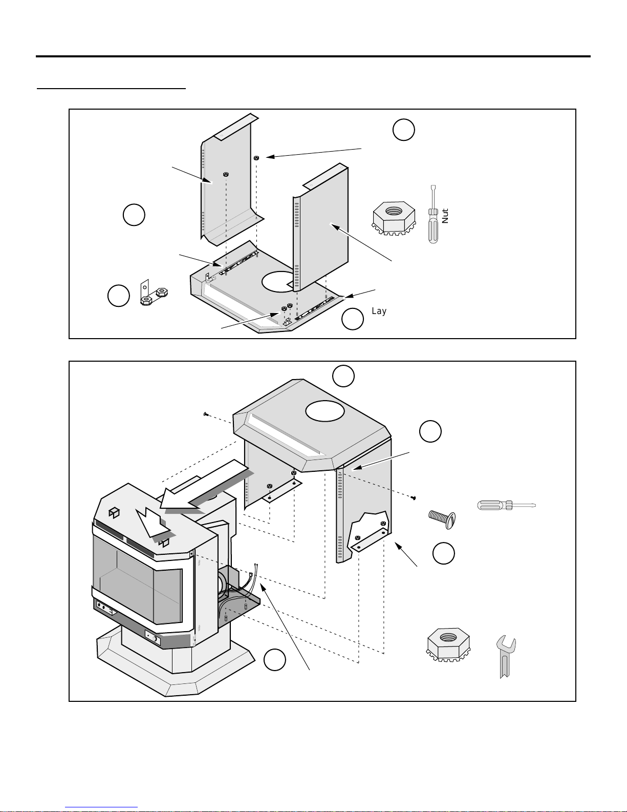
Stove Shell Assembly...............................7
Gas Inlet Installation ................................9
Floor Protection Requirements...................10
Stove Placement Requirements .................10
Gas Line Installation ................................11
Vent Requirements..................................12
Approved Vent Configurations....................13
Restrictor Position .............................13
Elbows............................................13
How to Measure Vent Lengths .............13
Approved Vent Config's with No Elbows
or Two 45°Offsets (Vertical Term.) .......14
Approved Vent Config's with a
Horizontal Termination........................15
Approved Vent Config's with a Vertical
Termination and Two 90°Elbows..........16
Horizontal Vent Termination Requirements...17
Vertical Vent Termination Requirements ......17
Electrical Connection ...............................17
Insert Installation
Installation Preparation.............................18
Items Required for Installation....................18
Packing Lists..........................................18
Order of Installation .................................18
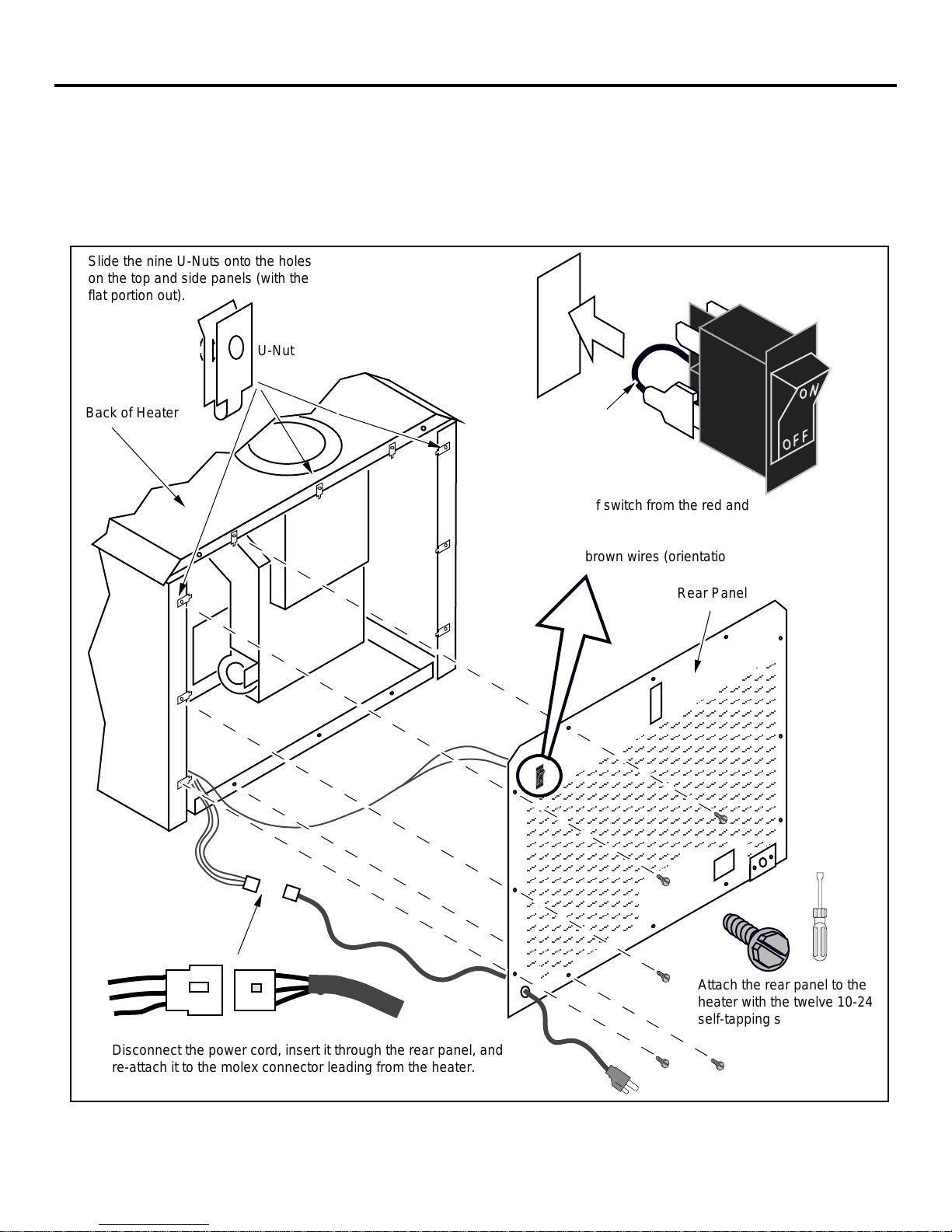
Installing the Power Cord..........................19
Insert Placement.....................................20
Floor Protection ......................................20
Gas Line Install.......................................21
Vent Requirements..................................22
Approved Vent Configurations....................23
Electrical Connection ...............................23
Surround Panel Installation........................24
Insert Shell Installation .............................25
Finalizing the Installation
1 Door Opening ......................................26
2 Log, Twig, and Ember Installation.............27
3 Glass Installation ..................................28
4 Purge and Leak Test the Gas Line ...........28
5 Pilot Flame Inspection............................28
6 Air Shutter Adjustment...........................29
7 Flame Inspection ..................................29
8 Explain Heater Operation to Owner ..........29
Operating Your Heater
Before You Begin....................................30
Location of Controls.................................30
Starting The Pilot Flame ...........................31
Starting the Stove for the First Time ............32
Turning the Stove On and Off ....................32
Adjusting the Flame Height........................32
Adjusting the Blower Speed.......................33
Normal Operating Sounds.........................33
Maintaining Your Stove
Maintaining Your Stove's Appearance..........34
Cleaning Your Stove................................34
Yearly Service Procedure..........................34
Troubleshooting
Troubleshooting Table..............................35
How this Stove Works ..............................36
Wiring Diagram.......................................37
Warranty.....................................................38
Listing Information ..................................39
Optional Equipment
Propane (LP) Conversion Kit .....................40
Thermostat ............................................44
Remote Control Thermostat.......................45
Gold Trim Kit..........................................46
Addendum
Altitude Considerations.............................47
Class A Chimney Conversion Kit ................47
Interior Masonry Chimney Conversions........47
Index 48
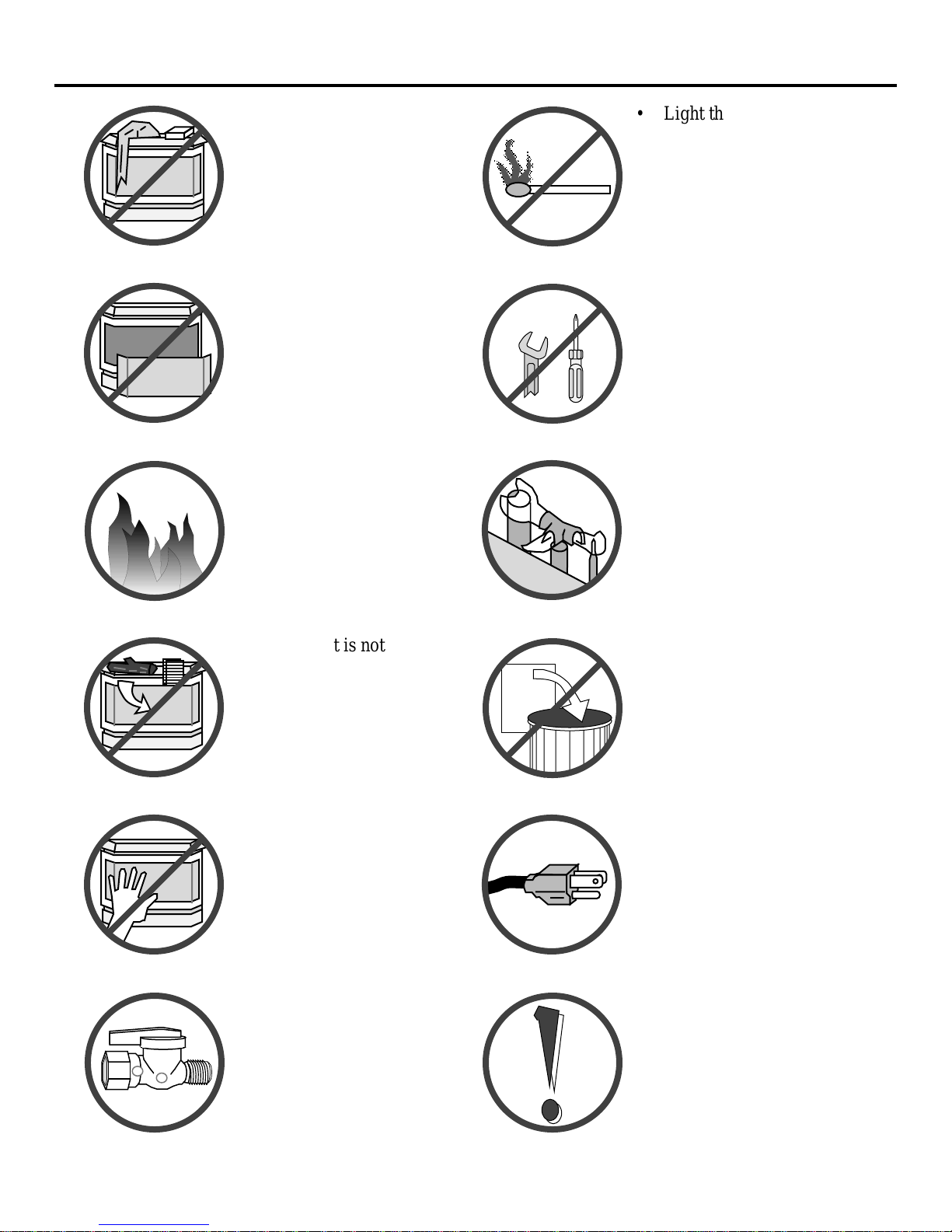
Symbols Used in this Manual
The illustration below details what the symbols used along the left margin indicate.
Requirement
•1!?+
Hint
NoteWarningStep

FEATURES AND SPECIFICATIONS PAGE 5
Installation Options:
• Residential or Mobile Home
• Freestanding Stove or Insert
• Bedroom Approved
• Alcove Approved
• Vertical or Horizontal Vent
Features:
• Works During Power Outages (standing pilot)
• High Efficiency
• Optional Thermostat or Remote Control
• Realistic "Wood Fire" Look
• Convenient Operating Controls
• Variable-Rate Heat Output
• Quiet Blower for Effective Heat Distribution
• Low Maintenance
Heating Specifications: Natural Gas LP (Propane)
Approximate Heating Capacity (in square feet)* 600 - 1600 600 - 1600
High Burn Input Rate (In BTU's) 38,500 36,500
Low Burn Input Rate (In BTU's) 18,700 18,000
Efficiency** 81 % 81.5 %
AFUE (Annual Fuel Utilization Efficiency) 72.4 % 73 %
* Heating capacity will vary with the home's floor plan and insulation, natural gas or Propane BTU rating, and outside temperature.
** Efficiency rating is a product of thermal efficiency rating determined under continuous operation independent of installed system.
To measure the net BTU's, multiply the BTU input by the efficiency percentage.
Dimensions
20"
(508 mm)
31-1/8"
(791 mm)
4-5/8"
(117 mm)
24-1/2" (622 mm)
The starter section is 2-5/8"
(67 mm) above the top panel
(includes flue collar
extension).
28-7/8"*
(733 mm)
8x10
Panels
31-7/8"*
(810 mm)
10x13
Panels
11-1/4"*
(286 mm)
8-3/4"*
(222 mm)
* Includes trim & standoffs
40-3/8"* 8x10 Panels
(1026 mm)
44-3/8"* 10x13 Panels
(1127 mm)
21-3/4"
(552 mm)
Standoff
4-5/8"
(117 mm)
19-1/2"
(495 mm)
Fuel: The stove is designed either for natural gas or for propane. Check
the sticker on the top of the gas control valve.
Emissions: This unit has passed the ANSI emission standards for vented room
heaters as tested by OMNI Environmental Services, Inc.
Electrical Specifications: 120 Volts, 1.3 Amps, 60 Hz (150 watts on high)

PAGE 6STOVE INSTALLATION - For Qualified Installers Only!
Installation Preparation
! Failure to follow all of the requirements may result in property damage, bodily injury, or even
death.
! This appliance must be installed in accordance with all local codes, if any; if not, follow ANSI
Z223.1 and NFPA 54(88).
! In Manufactured or Mobile Homes must confirm with: In USA, Manufactured Home Construction
and Safety Standard, Title 24 CFR, Part 3280; In Canada, CSA Z240.4 and Gas-Equipped
Recreational Vehicles and Mobile Housing. This appliance may be installed in Manufactured
Housing only after the home is site located.
! This appliance is designed for natural gas or propane (LP). Check the sticker on top of the gas
control valve.
! All exhaust gases must be vented outside the structure of the living-area. Combustion air is drawn
from outside the living-area structure.
! Notify your insurance company before hooking up this appliance.
! The requirements below are divided into sections - all requirements must be met simultaneously.
e
ms Required for Installation •Simpson Duravent with Silicone (see page 12 for part #'s)
•Avanti Pedestal (Part # 99200115)
•Avanti Stove Shell •Gas Hookup Equipment
e
ms Packed with the Avanti DV
•Avanti DV (with gold door)
•Log Set (2 Logs, 2 Twigs, Embers)
•Two Gas Inlet Pipes (the longer one is for stoves)
•Owner's Manual
•Propane Conversion Kit
•Strain Relief (for power cord)
•Strain Relief Bracket (for inserts only - may be discaded)
e
ms Packed with the Stove Shell
•Top, Left, Right, and Rear Stove Panels
•Control Cover
•Black Grill
•Eight 10-32 Hex Nuts with Attached Lock Washers
•Two 10-24 Pan Head Screws
•Twelve 10-24 Self-Tapping Screws
•Nine U-Nuts
•Two 6" strips of self-adhesive gasket
•Gas Line Plate
•Left & Right Forward Mounting Brackets
e
ms Packed with the Pedestal
•Pedestal
•Two 3/8 x 3/4" Bolts •Two Washers
•Two Lag Bolts
r
der of Installation 4Install the gas inlet (17-1/4" length of 3/8" pipe)
1If the heater is to use propane, install the propane
conversion kit (see pages 40 - 45)
2Attach the pedestal
3Attach the stove shell to the heater
5Position the heater, use floor protection if needed
6Connect the gas line. Connect the gas vent.
7Follow the instructions under "Finalizing the
Installation" on pages 26 through 29.
e
destal Attachment
9/16" Wrench
Use a 9/16" wrench to
attach the two pedestal
bolts to the bottom of the
heater.
Lift from here
NOTE: Keep the heater
level to prevent the door
from shifting loose.
The lag bolts and washers
may be inserted through
these holes to anchor the
pedestal to the floor.

STOVE INSTALLATION (CONT.)- For Qualified Installers Only! PAGE 7
Stove Shell Assembly
1Follow the directions below to install the side panels to the top panel.
AA
AA
Lay the top panel on a non-
scratching surface upside down.
Apply the two 6" long
gaskets along the
outside of the studs
Right side panel
Left side panel
Attach each Forward Mounting
Bracket with two 10-32 nuts.
Top panel
AA
AA
3/8" Nutdriver
a
b
c
d
Attach the side panels to the top panel with
the four 10-32 hex nuts (the smaller of the
two sizes) until the gasket compresses.
Do not over-tighten
the nuts – this may
cause damage to
the enamel finsih.
2Follow the instructions below to install the side and top panels.
Slide the top and side panels into place,
making sure they go underneath the wires
and gas line.
7/16" Wrench
Route the on/off switch and blower
wires to the right rear of the heater.
Attach the side panels to the heater
with four 1/4-20 hex nuts (reach in
from the rear of the heater with a
7/16" wrench to tighten).
Attach the forward brackets of
the top panel to the heater with
the two black screws.
Standard
Screwdriver
a
b
c
d

PAGE 8STOVE INSTALLATION (CONT.)- For Qualified Installers Only!
3Slide the nine U-Nuts into place (see the illustration below).
4Install the on/off switch (see the illustration below).
?If installing a thermostat or remote control, do so now (see pages 46 & 47).
5Disconnect the power cord, insert it through the rear panel, and re-attach it to the molex connector
leading from the heater (see the illustration below).
6Attach the rear panel to the heater (see the illustration below).
AA
AA
AA
A
A
A
A
A
A
A
A
AAA
AAA
AAA
AAA
AAA
AAA
AAA
AAA
AAA
AAAAAAAAA
AAAAAAAAA
AAAAAAAAA
AAAAAAAAA
AAAAAAAAA
AAAAAAAAA
AAAAAAAAAAA
AAAAAAAAAAA
AAAAAAAAAAA
AAAAAAAAAAA
AAAAAAAAAAA
AAAAAAAAAAA
AAAAAAAAAAA
AAAAAAA
AAAAAAA
AAAAAAA
AAAAAAA
AAAAAAA
A
A
A
A
A
A
A
A
A
A
AAAAAAAA
AAAAAAAA
AAAAAAAA
AAAAAAAA
AAAAAAAA
AAAAAAAA
AAAAAAAA
AAAAAAAA
AAAAAAAA
AAAAAAAA
A
A
A
A
A
A
A
A
AA
A
A
AA
A
A
A
A
AA
A
Slide the nine U-Nuts onto the holes
on the top and side panels (with the
flat portion out).
AA
A
AA
A
AA
A
AA
A
AA
A
AA
A
A
A
A
A
A
A
A
U-Nut
Back of Heater
Rear Panel
Disconnect the power cord, insert it through the rear panel, and
re-attach it to the molex connector leading from the heater.
AA
AA
AA
AAA
AAA
AAA
AAA
AAA
AAA
Attach the rear panel to the
heater with the twelve 10-24
self-tapping screws. Use a
5/16" nutdriver to tighten.
5/16" Nutdriver
Molex
Connection
AA
AA
AA
AA
A
A
A
A
A
AAA
AAA
AAA
AAA
AAA
AAA
Disconnect the on/off switch from the red and brown wires
leading from the heater. Insert the switch into the hole in
the upper left of the rear panel until it locks in place. Re-
attach the red and brown wires (orientation does not
matter).
Jumper Wire
(leave in place)
AA
AA
AA
AA
AA

STOVE INSTALLATION (CONT.)- For Qualified Installers Only! PAGE 9
6Pull gently on the power cord to take out any extra slack. Attach the strain relief (it is shipped
attached to the power cord - see the illustration below).
Strain Relief
Power Cord
Compress the strain
relief from the top and
bottom and insert it
into the hole until it
locks in place.
TO INSTALL THE
STRAIN RELIEF
7Attach the control cover by sliding it over the attachment hooks. Place the black grill in place.
The control cover hangs on two sets of hooks on both sides. Align
the control cover and slide the bracket onto the hooks and then
move downwards.
Bracket on
Control Cover Hooks on Side of Heater
Control Cover
Grill
a
s Inlet Installation
•Apply thread sealant to
one end of the gas inlet
and insert it through the
rear panel and into the
90°elbow on the gas
control valve. Tighten
with a pipe wrench.
!Leak check all gas line
connections.
A
A
A
A
A
A
A
A
A
AAA
AAA
AAA
AAA
AAA
AAA
AAA
AAA
AAA
AAAAAAAAA
AAAAAAAAA
AAAAAAAAA
AAAAAAAAA
AAAAAAAAA
AAAAAAAAA
AAAAAAAAAAA
AAAAAAAAAAA
AAAAAAAAAAA
AAAAAAAAAAA
AAAAAAAAAAA
AAAAAAAAAAA
AAAAAAAAAAA
AAAAAAAA
AAAAAAAA
AAAAAAAA
AAAAAAAA
AAAAAAAA
AAAAAAAA
AAAAAAAA
AAAAAAAA
AAAAAAAA
AAAAAAAA
AA
A
A
A
A
A
A
A
A
A
A
A
A
AA
AA
AA
A
A
Rear Panel
Gas Inlet
(3/8" diameter pipe)
A
17-1/4" (438 mm)
AA
AA
NOTE:
Apply thread sealant
prior to installing.

PAGE 10 STOVE INSTALLATION (CONT.)- For Qualified Installers Only!
Floor Protection Requirements
•When the stove is installed directly on carpeting, vinyl or other combustible material other than
wood flooring, the stove must be installed on a metal or wood protection panel extending the full
width and depth of the pedestal (Minimum 24-1/2" (622 mm) wide by 20" (508 mm) deep).
Stove Placement Requirements
•Heater must be installed on a level surface capable of supporting the heater and vent
•Due to the high temperature of the heater, it should be located out of traffic and away from furniture
and draperies. Heater must be placed so no combustibles are within, or can swing within 36" (910
mm) of the front of the heater (e.g. drapes, doors)
?When placed in a location where the floor to ceiling height is under 7 feet (2130 mm), the
installation is considered an alcove and must meet the following requirements:
•The alcove floor to ceiling height must be at least 58" (1470 mm) tall
•The alcove must not be more than 48" (1220 mm) deep before the ceiling returns to 7' (2130 mm)
• The alcove must be at least 44-1/2" (1130 mm) wide
•The stove must not be placed so the vents below or above the door, along the sides of stove, or along
the back of the heater can become blocked.
Minimum Clearances
10" Min.
(254 mm)
3" Min.
(76 mm)
When installed with
this clearance, the
vent is 4-1/4" (108
mm) from the back
wall, 19" (483 mm)
from the side wall.
45°
Straight Installations Corner Installations
When installed with
this clearance, the
vent is 12-3/4" j(324
mm) from the wall.
4" Min.
(102 mm)

STOVE INSTALLATION (CONT.)- For Qualified Installers Only! PAGE 11
Gas Line Install
!The gas line must be installed in accordance with all local codes, if any; if not, follow ANSI Z223.1
and the requirements listed below.
!The heater and gas control valve must be disconnected from the gas supply piping during any
pressure testing of that system at test pressures in excess of 1/2 psig (3.45 kPA). For pressures under
1/2 psig (3.45 kPA), isolate the gas supply piping by closing the manual shutoff valve.
•Leak test all gas line joints and the gas control valve prior to and after starting the heater.
F
uel
•This heater is designed for natural
gas but can be converted to propane.
Check the sticker on the top of the
gas control valve to make sure the
correct fuel is used.
G
as Line Connection
•The gas inlet accepts a 3/8" F.P.T.
Fitting
•The location of the gas inlet is
shown to the right
•A manual shutoff valve is required
for installation (it must be located
within 3' (910 mm) of the heater)
AAAAAAAAAAA
AAAAAAAAAAA
AAAAAAAAAAA
AAAAAAAAAAA
AAAAAAAAAAA
AAAAAAAAAAA
AAAAAAAAAAA
AAAAAAAAAAA
AA
AA
AA
AA
AA
AA
AA
AA
AAA
AAA
AAA
AAA
AAA
AAA
AAA
AAA
AAA
AAAAAAAAA
AAAAAAAAA
AAAAAAAAA
AAAAAAAAA
AAAAAAAAA
AAAAAAAAAAA
AAAAAAAAAAA
AAAAAAAAAAA
AAAAAAAAAAA
AAAAAAAAAAA
AAAAAAAAAAA
AAAAAAAAAAA
AAAAAAAA
AAAAAAAA
AAAAAAAA
AAAAAAAA
AAAAAAAA
AAAAAAAA
AAAAAAAA
AAAAAAAA
AAAAAAAA
AAAAAAAA
AA
AA
A
A
A
A
A
A
A
A
A
A
A
A
A
A
A
A
A
A
AA
12-3/4"
(324 mm)
4-3/4"
(121 mm)
1-1/2"
(38 mm)
Gas Inlet Pressure
•With the heater off, the inlet pressure must meet the requirements listed in the table below
?If the pressure is not sufficient, make sure the piping used is large enough and the total gas load for
the residence does not exceed the amount supplied.
?The supply regulator (the regulator that attaches directly to the residence inlet or to the propane tank)
should supply gas at the suggested input pressure listed below. Contact the local gas supplier if the
regulator is at an improper pressure.
Standard Input Pressure
Natural Gas 7" W.C. (1.74 kPA)
Propane 11" W.C. (2.73 kPA)

PAGE 12 STOVE INSTALLATION (CONT.)- For Qualified Installers Only!
Vent Requirements
!Always maintain the required 1" clearance (air space) to combustible materials to prevent a fire
hazard. Do not fill air spaces with insulation.
!The gas appliance and vent system must be vented directly to the outside of the building, and never
be attached to a chimney serving a separate solid fuel or gas-burning appliance. Each direct vent gas
appliance must use it's own separate vent system.
!If the stove is installed at an
altitude over 3,000 feet
(1,000 M) the flame quality
will need to be carefully
evaluated. See Addendum
#1, "Altitude
Considerations", on page 38.
•When the vent passes through
a wall, a wall thimble is
required. When the vent
passes through a ceiling, a
support box or firestop is
required. When the vent
passes through the roof, a
roof flashing and storm collar
are required. Follow the
instructions provided with the
vent (from Duravent®) for
installing these items.
Use a firestop spacer whenever
passing through a ceiling
(Duravent Part #963)
Vertical Termination
(Duravent Part # 991)
Use a roof flashing and storm collar
whenever passing through the roof
(Duravent Part #953 & #943 or #943S)
8-5/8"
(220 mm)
Use a support box
on exposed vent
Vertical Vent
Requirements
Use a wall thimble
whenever passing
through a wall
(Duravent Part #942)
Horizontal Termination
(Duravent Part #984)
Maintain a minimum 1" (25 mm)
clearance from vent to any combustible
(vent is 6 5/8" (170 mm) diameter)
Minimum
Framing for
wall thimble
Horizontal Vent
Requirements
Minimum framing
for fire stop
8-5/8"
(220 mm)
Maintain a minimum 1"
(25 mm) clearance from
vent to any combustible
(vent is 6 5/8" (170 mm)
diameter)
•Use Model GS Direct Vent manufactured by Simpson Dura-Vent only (or the Chimney Conversion
Kit - see Addendum #2). Follow the installation instructions included with the vent. For the nearest
Simpson Dura-Vent supplier, call (800) 835-4429. Part numbers and descriptions are listed below.
Straight Lengths
908B 6" Pipe Length, Black (interior)
907B 9" Pipe Length, Black (interior)
906 12" Pipe Length, Galvanized
906B 12" Pipe Length, Black (interior)
904 24" Pipe Length, Galvanized
904B 24" Pipe Length, Black (interior)
903 36" Pipe Length, Galvanized
903B 36" Pipe Length, Black (interior)
902 48" Pipe Length, Galvanized
902B 48" Pipe Length, Black (interior)
911B 11" to 14 5/8" Pipe, Adjustable, Black (interior)
Vent Terminations
981 Snorkel Termination (36" rise)
(for basement or raised
termination installations)
982 Snorkel Termination (14" rise)
(for basement or raised
termination installations)
984 Horizontal Square Termination
950 Vinyl Siding Standoff
991 Vertical Termination
Elbows
990 90• Elbow
990B 90• Elbow, Black (interior)
945 45°Elbow
945B 45°Elbow, Black (interior)
Penetration, Support Parts
942 Wall Thimble
941 Cathedral Ceiling Support Box
943 Flashing, 0/12 to 6/12 Roof Pitch
943S Flashing, 7/12 to 12/12 Roof Pitch
953 Storm Collar
963 Ceiling Firestop
988 Wall Strap
•Apply high-temperature silicone to the male section of inner
pipe (on the upper section of vent) so the silicone seals the
inner pipe from the outer pipe when the sections are
assembled. Slide the sections together and turn 1/4 turn until
the sections lock in place. Install three metal screws through
each joint to lock the outer section in place (see the
instructions included with the vent for further details).
•Horizontal sections require a 1/4" rise every 12" of travel
+Exterior Vent Diameter = 6-5/8", Inner Vent Diameter = 4"
Apply a 1/8" (3 mm)
bead of high-
temperature silicone
to the inner pipe.
The silicone must
seal the inner pipe
from the outer pipe.
Silicone
•Horizontal sections require non-combustible support every three feet (e.g.: plumbing tape)
•Seal the inner vent to the appliance.

STOVE INSTALLATION (CONT.)- For Qualified Installers Only! PAGE 13
Approved Vent Configurations
R
estrictor Position
•A vent restrictor is built
into the appliance to
adjust the flow rate of
exhaust gases. This
ensures proper flames
for the wide variety of
vent configurations. The
restrictor consists of a
butterfly valve below the
starter section of pipe
and an adjustment plate
with index holes used to
hold the valve in a fixed
position. Depending
upon the vent
configuration, you may
be required to adjust the
restrictor position. The
charts for approved vent
configurations describe
which position the vent
restrictor must be in.
A
A
A
A
A
AAA
AAA
AAA
AAA
AAA
AAAAA
AAAAA
AAAAA
AAAAAA
AAAAAA
AAAAAA
AAAAAA
AAAAAA
AAAAA
AAAAA
AAAAA
AAAAA
AAAAA
AAAAA
A
A
A
A
A
A
A
A
A
A
A
A
A
AA
AA
A
A
A
To Adjust the Restrictor:
1
2
3
4
The eleven holes on the
restrictor plate
correspond to the eleven
restrictor positions.
NOTE:
Position #1 is the
fully open position
Determine the correct
restrictor position (see the
charts under "Approved
Vent Configurations" - the
stock position is #1).
Remove the screw with a
1/4" nutdriver (or
screwdriver).
Rotate the adjustment plate
clockwise until the correct
index hole is below the pivot
point.
Insert the screw into the
correct index hole and
tighten.
Adjustment
Plate
1/4" Nutdriver
Index Holes
Pivot Point This restrictor is
in Position #5.
Screw
Rotate the
adjustment
plate to change
the restrictor
position.
123456789
10
11
E
lbows
•2 Elbow
maximum
(two 45°or
two 90°, not
one 45°and
one 90°)
M
easuring Vent
L
engths
Vent Horizontal Run
(measure from the closest
edge of the starter section to
the end of the termination)
Vent Height is
calculated to the
top of the vent on
horizontal
terminations and
to the top of the
termination on
vertical
terminations.
Vent
Height
Elbows add 3" (75 mm) to the
length of the vent system.
Side
View
9-5/8"
(245 mm)
Vent Length
(3', 4', etc.)
(910, 1210 mm)
Vent sections overlap each
other by 1-1/2" (37 mm)
8-3/4" (220 mm) wide
with 1-1/2" (37 mm)
to 3-3/8" (85 mm) of
overlap
The starter section is 7/8"
(22 mm) below the top (if
using the flue collar
extension, if is 2-5/8" (67
mm) above the top panel)
12-3/8" (310 mm) tall
with 1-1/2" (37 mm)
of overlap
3" (75 mm)
1-1/2" (37 mm)
1-1/2"
(37 mm)

PAGE 14 STOVE INSTALLATION (CONT.)- For Qualified Installers Only!
A
pproved Venting Configurations for
V
ertical Terminations with (or without)
T
wo 45°Elbows
•10' (3 M) Minimum System Height
(with or without offsets)
•33' (10 M) Maximum System Height
•6' (1.8 M) Maximum Offset
•The termination must fall within the shaded
area shown in the chart. Use the indicated
restrictor position.
•If using offsets, use the table below to
calculate the vertical rise and horizontal
offset
Offset
Length
Horizontal
Offset
Vertical
Rise
Offset Length Hor. Offset Vert. Rise
None 5" (125 mm) 1' (300 mm)
1' Section 1' (300 mm) 1' 7" (480 m
m
2' Section 1' 9" (530 mm) 2' 4" (710 m
m
3' Section 2' 5" (740 mm) 3' (915 mm)
4' Section 3' 2" (965 mm) 3' 8" (1.12 M
)
4' + 1' Section 3' 9" (1.14 M) 4' 4" (1.32 M
)
4' + 2' Section 4' 6" (1.37 M) 5' (1.52 M)
4' + 3' Section 5' 2" (1.57 M) 5' 9" (1.75 M
)
AAAAAA
AAAAAA
AAAAAA
AAAAAA
AAAAAA
AAAAAA
AAAAAA
AAAAAA
AAAAAA
AAAAAA
AAAAAA
AAAAAA
AAAAAA
AAAAAA
AAAAAA
AAAAAA
AAAAAA
AAAAAA
AAAAAA
AAAAAA
AAAAAA
AAAAAA
5 feet
(1.5 M)
10 feet
(3 M)
(min.)
15 feet
(4.6 M)
20 feet
(6 M)
25 feet
(7.5 M)
30 feet
(9.1 M)
0 feet
33' (max)
(10 M)
0 feet
3 feet
(0.9 M)
6' (max)
(1.8 M)
5 feet
(1.5 M)
0 feet
0 feet
Restrictor
Position # 5
The maximum
offset lengths is
two 4' sections.
NOTE:
Restrictor positions
are based upon lab
tests. The ideal
restrictor position
may vary slightly,
especially when the
termination is near
a demarkation line.
Restrictor
Position # 7
Do not place an
offset directly off the
top of the heater.
3 feet
(0.9 M)
6' (max)
(1.8 M)
10 feet
(3 M)
(min.)
15 feet
(4.6 M)
20 feet
(6 M)
25 feet
(7.5 M)
30 feet
(9.1 M)
33' (max)
(10 M)

STOVE INSTALLATION (CONT.)- For Qualified Installers Only! PAGE 15
Approved Venting Configurations with a Horizontal Termination
•A Minimum of 2' (.5 M) rise is required directly off of the stove
• A minimum of 1' (.3 M) run is required
•If using a Snorkel Termination (14"[.4 M] or 36" [.9 M]) add the snorkel height to the vertical
height.
•The termination must fall withinin the shaded area shown in the chart. Use the indicated restrictor
position.
AAAAAAAAA
AAAAAAAAA
AAAAAAAAA
AAAAAA
AAAAAA
AAAAAA
AAAAAA
5' (min.)
(1.5 M)
0 feet
11' (max)
(3.4 M)
5 feet
(1.5
M)
0 feet
5 feet
(1.5
M)
12'(max)
(3.7 M)
0 feet
0 feet
NOTE:
Horizontal sections require a 1/4" (6 mm) rise every 12" (300 mm) of travel.
12'(max)
(3.7 M)
NOTE:
Restrictor positions
are based upon lab
tests. The ideal
restrictor position may
vary slightly,
especially when the
termination is near a
demarkation line.
Restrictor
Position # 5
NOTE:
A minimum 2' (.5 M) rise is
required directly off of the stove.
NOTE:
A minimum 1' (.3 M)
horizontal run is required.
Restrictor
Position # 1 5' (min.)
(1.5 M)
11' (max)
(3.4 M)

PAGE 16 STOVE INSTALLATION (CONT.)- For Qualified Installers Only!
Approved Venting Configurations for Vertical Terminations with Two 90°Elbows
•The termination must fall within the shaded area shown in the chart. Use the indicated restrictor position.
AAAAAAAAAAAAAA
AAAAAAAAAAAAAA
AAAAAAAAAAAAAA
AAAAAAAAAAAAAA
AAAAAAAAAAAAAA
AAAAAAAAAAAAAA
AAAAAAAAAAAAAA
AAAAAAAAAAAAAA
AAAAAAAAAAAAAA
AAAAAAAAAAAAAA
AAAAAAAAAAAAAA
AAAAAAAAAAAAAA
AAAAAAAAAAAAAA
AAAAAAAAAAAAAA
AAAAAAAAAAAAAA
AAAAAAA
AAAAAAA
AAAAAAA
AAAAAAA
AAAAAAA
AAAAAAA
AAAAAAA
AAAAAAA
AAAAAAA
AAAAAAA
AAAAAAA
AAAAAAA
AAAAAAA
AAAAAAAAAAAAAA
AAAAAAAAAAAAAA
AAAAAAAAAAAAAA
AAAAAAAAAAAAAA
AAAAAAAAAAAAAA
AAAAAAAAAAAAAA
AAAAAAAAAAAAAA
AAAAAAAAAAAAAA
AAAAAAAAAAAAAA
AAAAAAAAAAAAAA
AAAAAAAAAAAAAA
AAAAAAAAAAAAAA
AAAAAAAAAAAAAA
AAAAAAAAAAAAAA
AAAAAAAAAAAAAA
AAAAAAAAAAAAAA
AAAAAAAAAAAAAA
AAAAAAAAAAAAAA
AAAAAAAAAAAAAA
AAAAAAAAAAAAAA
AAAAAAAAAAAAAA
NOTE:
Horizontal sections require a 1/4" (6 mm)
rise every 12" (300 mm) of travel.
Restrictor
Position # 7
Restrictor
Position #6
NOTE:
Restrictor positions are
based upon lab tests.
The ideal restrictor
position may vary
slightly, especially when
the termination is near a
demarkation line.
11 feet (min.)
Restrictor
Position # 5
Restrictor
Position # 4
NOTE:
A min. 8' (2.4 M) of vertical
vent must be used.
NOTE:
The vent
must
terminate
within one
of the
shaded
regions.
0 feet
5 feet
(1.5 M)
10 feet
(3 M)
0 feet
0 feet
0 feet
16'(max)
(4.9 M)
8 feet (min.)
(2.4 M)
5 feet
(1.5 M)
10 feet
(3 M)
15 feet
(4.6 M)
20 feet
(6 M)
25 feet
(7.5 M)
30 feet
(9.1 M)
35' (max)
(10.7 M)
5 feet
(1.5 M)
10 feet
(3 M)
15 feet
(4.6 M)
20 feet
(6 M)
25 feet
(7.5 M)
30 feet
(9.1 M)
35' (max)
(10.7 M)
8 feet (min.)
(2.4 M)
5 feet
(1.5 M)
10 feet
(3 M)
16'(max)
(4.9 M)

STOVE INSTALLATION (CONT.)- For Qualified Installers Only! PAGE 17
Horizontal Vent Termination Requirements (see the illustration below)
A Minimum 9" (225 mm) clearance from any door or window
B Minimum 12" (300 mm) above any grade, veranda, porch, deck or balcony
C Minimum 12" (300 mm) from outside corner walls
D Minimum 12" (300 mm) from inside corner walls
E Minimum 11" (275 mm) clearance below unventilated soffits or roof surfaces
Minimum 18" (450 mm) clearance below ventilated soffits
Minimum 6" (150 mm) clearance from roof eaves
NOTE: Vinyl surfaces require 24" (600 mm)
11” Min.
6” Min.
Roof
Surface
Roof
Eaves
F Minimum 18" (450 mm) clearance below a veranda, porch, deck or balcony (must have two open sides)
G Minimum 48" (1220 mm) clearance from any adjacent building
H Minimum 84" (2130 mm) clearance above any grade when adjacent to public walkways or driveways
NOTE: may not be used over a walkway or driveway shared by an adjacent building
I Minimum 48" (1220 mm) clearance from any mechanical air supply inlet, 72" (1820 mm) for Canada
J Minimum 36" (910 mm) clearance above and 48" (1220 mm) below and to the sides of non-mechanical air supply inlet
K Minimum 36" (910 mm) from the area above the meter/regulator (vent outlet)
L Minimum 36" (910 mm) from the meter/regulator (vent outlet)
C
B
H
E
GA
D
F
L
KJ
I
NOTE: Measure clearances to the nearest edge of the exhaust hood.
A
E
•Use the vinyl siding standoff (#950) when installing on an exterior with vinyl siding.
•Vent termination must not be located where it will become plugged by snow or other material
•These clearances meet UMC-1994 and the CNA/CGA-B149 code standards
Vertical Vent Termination Requirements (see the illustration below)
Roof Pitch
Flat to 6/12
6/12 to 8/12
8/12 to 9/12
9/12 to 10/12
10/12 to 11/12
11/12 to 12/12
12/12 to 14/12
14/12 to 16/12
16/12 to 18/12
18/12 to 20/12
20/12 or greater
Minimum Height*
1' (.3 M)*
1.5' (.45 M)*
2' (.6 M)
2.5' (.75 M)
3.25' (1 M)
4' (1.2 M)
5' (1.5 M
6' (1.8 M)
7' (2.15 M)
7.5' (2.25 M)
8' (2.45 M)
* In Canada the
vent termination
must be a
minimum 2' (.6 M)
tall and 2' (.6 M)
above any portion
of the roof within
10' (3 M) of the
vent.
Use the
chart to the
right to
determine
the required
vent
termination
height.
Height
Roof
Pitch
Use the vertical
termination (Part #991)
Electrical Connection
•Plug the power cord into a grounded 120 Volt outlet (do not remove the grounding plug).

PAGE 18 INSERT INSTALLATION - For Qualified Installers Only!
Installation Preparation
! Failure to follow all of the requirements may result in property damage, bodily injury, or even death.
! This appliance must be installed in accordance with all local codes, if any; if not, follow ANSI
Z223.1 and NFPA 54(88).
! In Manufactured or Mobile Homes must confirm with: In USA, Manufactured Home Construction
and Safety Standard, Title 24 CFR, Part 3280; In Canada, CSA Z240.4 and Gas-Equipped
Recreational Vehicles and Mobile Housing. This appliance may be installed in Manufactured
Housing only after the home is site located.
! This appliance is designed for natural gas or propane (LP). Check the sticker on top of the gas
control valve.
! All exhaust gases must be vented outside the structure of the living-area. Combustion air is drawn
from outside the living-area structure.
! Notify your insurance company before hooking up this appliance.
! The requirements below are divided into sections - all requirements must be met simultaneously.
Items Required for Installation
•Avanti Insert Shell and Surround Panels
•Direct Vent Insert Adapter (see page 22) •Gas Hookup Equipment
Items Packed with the Avanti DV
•Avanti DV (with gold door)
•Log Set (2 Logs, 2 Twigs, Embers)
•Two Gas Inlet Pipes (the shorter one is for inserts)
•Owner's Manual
•Propane Conversion Kit
•Flue Collar Extension (not used for insert installations)
•Strain Relief (for power cord)
•Strain Relief Bracket
Items Packed with the Insert Panel Kit
•Top, Left, and Right Surround Panels
•Two Leveling Bolts •Trim Kit (3 pieces trim, 2 "L" brackets, set screws, double-
back tape)
Items Packed with the Insert Shell Kit
•Upper Top
•Control Cover •Hardware Pack (2 Upper Top Brackets, 4 6-32 Nuts, 2 10-24
Phillips Screws)
Order of Installation
1If the heater is to use propane, install the propane
conversion kit (see pages 40 - 45)
2Install the
g
as inlet (8-3/4" (222 mm) len
g
th of 3/8"
p
i
p
e)
3Install the power cord
4Position the heater (see "Heater Placement")
5Connect the gas line. Connect the gas vent.
6Install the logs and test the heater (see the instructions
under "Finalizing the Installation")
7Install the insert panel kit.
8Install the insert shell kit.
9Follow the instructions under "Finalizing the
Installation" on pages 26 through 29.
Installing the Gas
Inlet
•Locate the 8-3/4" (222
mm) gas inlet pipe
included with the
heater (the longer one
may be discarded).
Apply thread sealant to
one end and insert it
through the rear of the
insert into the 90°
elbow on the gas
control valve (see the
illustration below).
Tighten with a pipe
wrench.
Back of
Heater
AAAAAA
AAAAAA
AAAAAA
AAAAAA
A
A
AA
A
AA
AA
A
A
A
A
Gas Inlet
(3/8" diameter pipe)
AA
AA
8-3/4" (222 mm) Insert the gas inlet through
here and into the elbow directly
off the gas control valve.
AAAAAAA
AAAAAAA
AAAAAAA
AAAAAAA
A
A
A
A
AA
AA
A
A
AA
A
NOTE:
Apply thread sealant
prior to installing.
NOTE:
With the insert in
place, the gas line
center is located
4-1/4" (108 mm)
back from the
fireplace opening,
1-5/8" (41 mm)
above the hearth,
and 7-1/2" (191
mm) from the
center of the
insert.

INSERT INSTALLATION (CONT.)- For Qualified Installers Only! PAGE 19
Installing the Power Cord
1The power cord may be located on either side. Place the strain relief bracket (included in the owner's
pack) over the two studs and tighten with two 1/4-20 hex nuts (see illustration below).
A
A
AA
A
A
AAAAAAA
AAAAAAA
AAAAAAA
AAAAAAA
AAAAAAA
AA
AA
A
A
A
AA
AA
AA
Back of
Heater
A
Attach the strain relief bracket
with two 1/4-20 hex nuts. Disconnect the power cord, insert it through the rear panel, and
re-attach it to the molex connector leading from the heater.
Molex
Connection
AAA
AAA
AAA
A
A
A
AA
AA
7/16" Nutdriver
A
A
A
AAAA
AAAA
AAAA
A
A
A
A
A
AAAAAAA
AAAAAAA
AAAAAAA
AAAAAAA
AAAAAAA
A
A
A
A
A
2Pull gently on the power cord to take out any extra slack. Attach the strain relief (it is shipped
attached to the power cord - see the illustration below).
Strain
Relief
Compress the
strain relief from
the top and
bottom and
insert it into the
hole until it locks
in place.
TO INSTALL THE
STRAIN RELIEF
Power Cord

PAGE 20 INSERT INSTALLATION (CONT.)- For Qualified Installers Only!
Insert Placement
The Insert Must be
Placed 11-1/4" (286 mm)
into the Fireplace.
Run the brown and red
wire (for the on/off switch)
to the right side along the
facing.
Run the power cord to
either side of the insert
along the facing.
The insert must be in place with
the gas line and vent attached
prior to installing the panels.
Min. 27-3/4" (705 mm) WIde - includes
6" (150 mm) for gas line installation
Min. 21-1/2"
(550 mm) Tall -
includes 2" (50
mm) for vent
installation
The gas line faces to the rear
and its center is 4-1/4" (108 mm)
back from the fireplace opening,
1-5/8" (41 mm) above the
hearth, and 7-1/2" (191 mm)
from the center of the insert.
NOTE:
When using the 45° vent, an
additional 4" (100 mm) is
required behind the rear
edge of the baseplate for
vent hook-up.
Use the leveling bolts for
fireplaces with recessed
floors (included with the
surround panels).
•Insert must be placed so no combustibles are within, or can swing within 36" (910 mm) of the front
of the heater (e.g. drapes, doors)
•The insert may be placed inside a masonry fireplace or listed zero-clearance (metal) fireplace
•The insert must be installed in a level, undamaged fireplace (damage must be repaired prior to
installation).
•The insert must maintain 10" (254 mm) clearance to sidewalls (measure from the upper top)
•Non-combustible facing (e.g. brick, tile) must extend 8" (203 mm) minimum from the side and 12"
(305 mm) to the top of the insert (measure from the upper top)
•Combustible mantles must be a minimum 17-1/2" (445 mm) above the top of the insert (measure
from the upper top)
Floor Protection
•The heater must be installed on a non-combustible hearth and may not extend over combustible
flooring
Table of contents
Popular Heater manuals by other brands

Herschel
Herschel XLS500TW-INT manual

Strend Pro
Strend Pro DIX-020Y instruction manual

Clarke
Clarke DEVIL 350B 230V Operating & maintenance instructions

Soleus Air
Soleus Air HC4-15-32 operating instructions

Argo
Argo SPLITTO JR Installation and operation instructions

Ventamatic
Ventamatic HETR H1800 owner's manual