User Manual
www.AvantcoEquipment.com 3
Installation
Carefully unpack the hot water dispenser and inspect for
damage and missing parts.
1. Place hot water dispenser on sturdy, level, heat resistant, non-ammable surface near power supply and water supply.
Do not connect water line or power cord at this time.
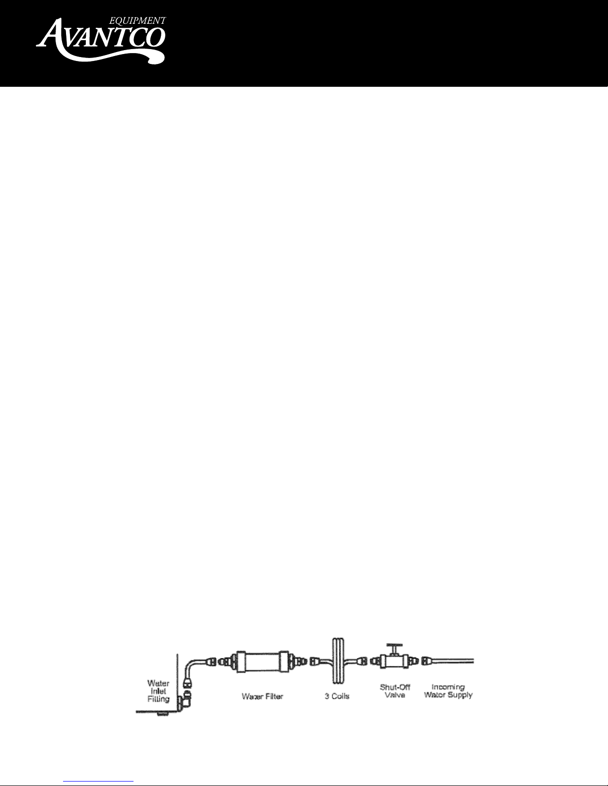
2. Form three coils of 1/4” O.D. copper tubing or high pressure exible hose (not supplied) and connect to the cold water line.
The coils allow the dispenser to be moved easily for cleaning and servicing. Flush incoming water in the line. See diagram Fig. 1.
Note: It is recommended that an optional shut o valve and water lter be installed on the water line at this time.
3. Attach the water line to the water inlet tting located on the rear of the dispenser. Hold the dispenser water inlet tting with a
wrench when tightening the water line.
4. Turn on water supply
5. Check for water leaks at water inlet. Tighten ttings if necessary.
6. Connect power supply cord into proper power supply as indicated on electrical nameplate.
Note: This dispenser is designed to operate with a water pressure between 30 to 80PSI. When water pressure exceeds
80PSI, it is recommended that an optional water pressure regulator be installed to reduce water pressure to 50 PSI.
For installation of less than 25 feet use 1/4’’ O.D. copper tubing. For installation of more than 25 feet use 3/8’’ O.D.
copper tubing and use and adapter for connection as necessary.
Operation
1. Ensure the O/On toggle switch on back of unit is in the o (down) position .
2. As soon as the unit is plugged in, it will begin to ll. It will automatically stop when the water has reached the proper level.
3. Turn O/On toggle switch on the rear to the On (up) position.
4. Allow the dispenser to reach the proper temperature. This will occur in approximately 20 minutes. The green pilot light will
come on when the unit is ready.
5. Place an empty cup or container directly under the faucet and pull faucet handle towards you. When nished, release the handle.
Note: Due to water expansion during initial heat up on installation, excess water may ow from the drain spout.
Plumber’s instrucons:
Plumbing Connecon Diagram Fig.1