Avantco A36123 User manual

Dozer Blade 2000 2016 1
Operator's Manual for Attachment
Dozer Blade 2000
Dozer Blade 2500
Product number
2000 mm
A36123
2500 mm
A36251
English
www.avanttecno.com

Dozer Blade 2000 2016 1

Dozer Blade 2000 2016 1
CONTENTS
1. FOREWORD ........................................................................................................................................ 4
2. DESIGNED PURPOSE OF USE.......................................................................................................... 5
3. SAFETY INSTRUCTIONS FOR USING THE ATTACHMENT...................................................... 6
4. TECHNICAL SPECIFICATIONS ....................................................................................................... 8
4.1 Safety labels and main components of the attachment ....................................................................................8
5. ATTACHING THE ATTACHMENT ................................................................................................. 10
5.1 Connecting and disconnecting the hydraulic hoses...........................................................................................11
6. INSTRUCTIONS FOR USE ................................................................................................................ 13
6.1 Checks before use .....................................................................................................................................................13
6.2 Operating the dozer blade.......................................................................................................................................14
6.2.1 Blade slewing.......................................................................................................................................................14
6.2.2 Blade floating .......................................................................................................................................................15
6.3 Blade spring release system.....................................................................................................................................15
6.3.1 Locking the blade ...............................................................................................................................................16
6.4 Skid shoes.....................................................................................................................................................................16
6.4.1 Use of support wheels......................................................................................................................................16
6.5 Blade extensions.........................................................................................................................................................17
6.6 Blade edge plate..........................................................................................................................................................17
7. MAINTENANCE AND SERVICE ....................................................................................................... 19
7.1 Checking hydraulic components ............................................................................................................................19
7.2 Cleaning the attachment...........................................................................................................................................20
8. WARRANTY TERMS .......................................................................................................................... 20

4 (22)
1. Foreword
Avant Tecno Oy would like to thank you for your purchase of this attachment for your Avant loader. It has
been designed and manufactured on the basis of years of experience on product development and
manufacturing. By familiarising yourself with this manual and following the instructions, you ascertain your
safety and ensure the reliable operation and long service life of the equipment. Read the instructions carefully
before starting to use the equipment or performing maintenance.
The purpose of this manual is to help you to:
operate the equipment in a safe and efficient manner
observe and prevent any hazardous situations
keep the equipment intact and ensure a long service life
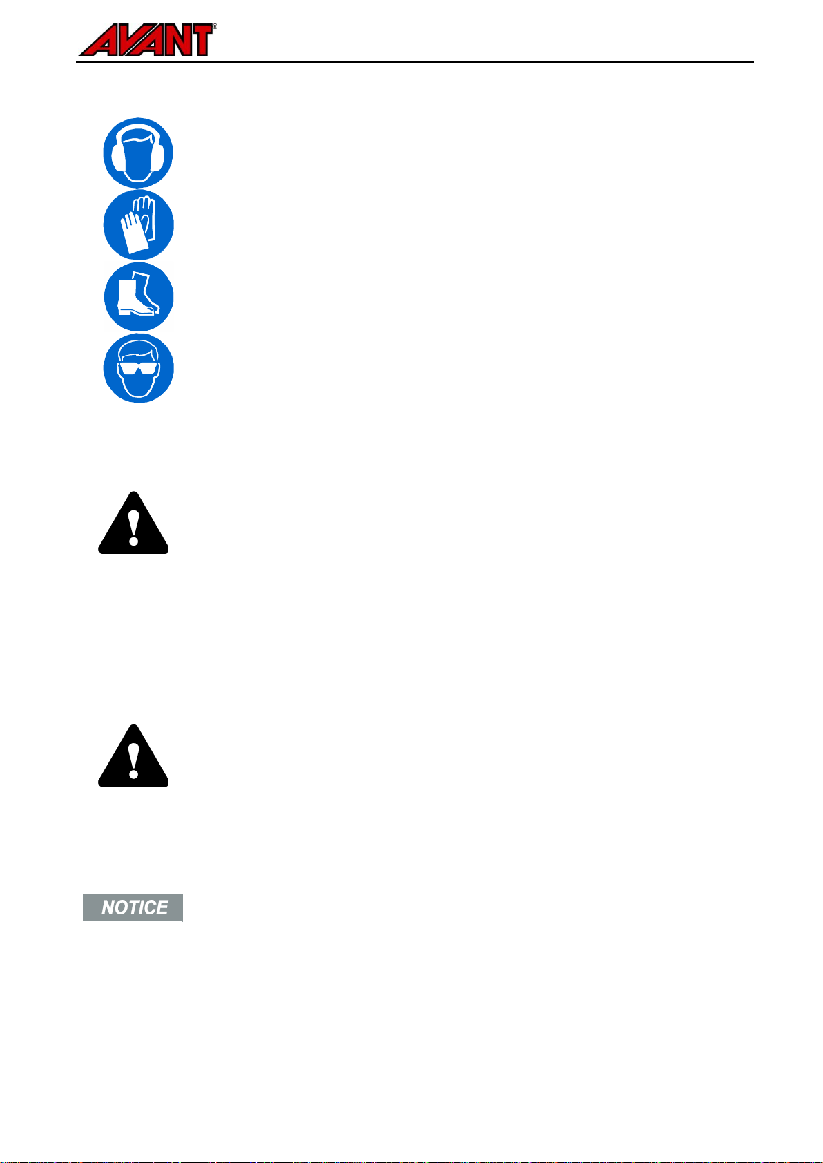
The following warning symbols are used throughout this manual to indicate factors that must be taken into
account to reduce the risk of personal injury or damage to property:
WARNING:
This safety symbol refers to important safety information in this manual.
It warns of an immediate hazard that could cause serious personal
injury.
Read the warning text accompanying the symbol carefully and ensure
that other operators are also familiar with the warnings, since personal
safety is at stake.
This signal word indicates information about the correct operation and maintenance
of the equipment.
Failure to observe the instructions accompanying the symbol can lead to equipment
breakdown or other property damage.
With these instructions, even an inexperienced user can use the attachment and loader safely. The manual
includes important instructions for experienced AVANT operators as well. Ensure that all persons using the
loader have received proper guidance and familiarised themselves with the manual of the loader, each
attachment that are used, and all safety instructions before using the equipment. Using the equipment for
other purposes or use in any other way than described in this manual is prohibited. Keep this manual at hand
throughout the service life of the equipment. If you sell or transfer the equipment, be sure to hand over this
manual to the new owner. If the manual is lost or damaged, you can request a new one from your Avant
dealer or from the manufacturer. Due to continuous product development some of the details shown in this
manual may differ from your equipment. This manual contains the original instructions in English.
In addition to the safety instructions included in this manual, you must observe all occupational safety
regulations, local laws, and other regulations concerning the use of the equipment. Particularly the regulations
concerning the use of the equipment on public road areas must be observed. We reserve the right to change
the contents of the manual without notification.

5 (22)
2. Designed purpose of use
The AVANT Dozer Blade 2000 is an attachment suitable for use with AVANT multi purpose loaders shown in
Table 1. The dozer blade is intended for ploughing snow, and can also be used for ploughing soil or sand. As
standard, the blade is equipped with hydraulic slewing, which enables to choose the side to which the material
will be transferred without interrupting work. The blade is equipped with spring release mechanism which
protects the blade and driver in case it hits an obstacle.
The two solid skid shoes as standard equipment reduce blade wear and improve manoeuvrability. Support
wheels (2 pcs), instead of skid shoes, are available as an option –they keep the working height more constant
when working on sensitive surfaces like pavings.
The standard blade extensions can be mounted so that the blade is straight, or if they are mounted the other
way around, the blade will collect the material being ploughed. The blade edge is made from superior quality
wear restistant steel, and can be replaced if needed. Rubber blade and ice cutting blades available as an
option.
The attachment has been designed to require as little maintenance as possible. The operator can perform
regular maintenance tasks. All repair work can’t be performed by the operator, and demanding repair and
maintenance operations are to be left for professional maintenance. All maintenance work must be done using
proper safety equipment. Spare parts must be identical with original specifications, which can be ensured by
using only original spare parts. A separate spare parts catalog may be available, consult your Avant dealer.
Familiarise yourself with the manual's instructions regarding service and maintenance. Please contact your
AVANT retailer if you have additional questions about the operation or maintenance of the equipment, or if
you require spare parts or maintenance services.
Table 1 - Dozer Blade 2000 - Compatibility with Avant loaders
Avant
216
218
220
220series 2
225
225LPG
313S
320S
320S+
419
420
520
R20
525LPG
R28
528
630
R35
635
640
745
750
760i
A36123
-
.
-
A36251
-
-
-

6 (22)
3. Safety instructions for using the attachment
Please bear in mind that safety is the result of several factors. The loader-attachment combination is highly
powerful and improper or careless use or maintenance may cause serious personal injury or property
damage. Due to this, all operators must carefully familiarise themselves about correct use and the operator's
manuals of both the loader and the attachment before starting operation. Do not use the attachment if you
have not completely familiarised yourself with its operation and the related hazards.
Misuse, careless use, or using an attachment that is in poor condition, may cause
risk of serious injuries. Familiarise yourself with the controls of the loader, correct
coupling procedure, and the correct way to operate the attachment at a safe area.
Study especially how to stop the equipment in a safe manner. Read all safety
precautions carefully.
Read all safety instructions carefully before handling the attachment
When attaching an attachment to the loader, ensure that the locking pins of the
loader's quick attach plate are in the lower position and that they have locked
the attachment to the loader. Never lift or move an unlocked attachment.
The Dozer Blade 2000 is designed to be used by one operator at a time. Do not let
others near the danger area of the equipment when it is in use.
Always transport the attachment as low as possible to keep the centre of gravity low,
and keep the telescopic boom retracted during driving.
Do not drive at high speed unless you can be sure that there are no obstacles at the
working area. The loader may stop suddenly if it hits an obstacle, regardless of the
spring release mechanism. Remember that there may be hidden obstructions or
fragile surfaces under the snow.
Shut down the loader and place the attachment to a safe position as shown in Safe
stopping procedure before any cleaning, maintenance, or adjustments.
Pay attention to the surroundings and any other persons and machines moving in the
vicinity. Pay attention to the contours of the terrain and other hazards, such as
branches and trees that can reach to the driver's area, loose rocks, and slippery
surfaces.
Make sure to use only an attachment that is in good condition. Do not modify the
attachment in any way that could affect its safety.
Use the attachment only for its intended purpose. Other use may create unnecessary
safety risks, and the equipment may get damaged.
Make sure that the loader is equipped with necessary safety components, and that
they are in working condition. Seat belt must be used. If there are specific hazards
related to the operating area, use appropriate safety equipment.
Also read the safety instructions and correct use of the loader from the operator's
manual of the loader.

7 (22)
Remember to wear proper protective clothing:
The noise level at the driver's seat may exceed 85 dB(A). Wear hearing protection
while working with the loader.
Wear protective gloves.
Wear safety boots whenever working with the loader.
Wear safety glasses when handling hydraulic components.
Safe stopping of the attachment, before going near the attachment:
Always stop the attachment following safe stopping procedure before leaving the
driver's seat. Safe stopping procedure prevents all unintentional movements of the
attachment. Note that the loader boom can move down even if the engine of the
loader is turned off. Safe stopping procedure:
Lower the boom and the attachment on the ground.
Shut down the loader engine and lock the parking brake.
Release residual pressure from the hydraulic system; move all hydraulic control
levers to their extreme positions a couple of times.
Prevent starting of the machine, remove ignition key.
Never allow anyone to get under the raised load or the loader boom. Keep in mind that the
loader boom can be lowered or tilted even if the engine has been shut down (crushing
hazard). The loader is not intended to be left to keep a load elevated for longer periods.
Always lower the attachment to a safe position before leaving the driver's seat.
Observe the local regulations concerning the use of the equipment on public roads. The
loader may need to be registered for road use. Contact your local Avant dealer or local
authorities for more information.

8 (22)
4. Technical specifications
Table 2 - Dozer Blade 2000 - Technical specifications
Product number
A36123
A36251
Total width:
2146 mm
2594 mm
Working width, with extensions
1392 mm
2840 mm
Slewing angle:
± 30°
Hydraulic
± 30°
Hydraulic
Weight, with extensions:
215 kg
232 kg
Maximum input of hydraulic energy:
max 22,5 MPa (225 bar)
Compatible Avant loaders:
See Table 1
Optional extras:
Rubber blades, kit for main blade and
extensions:
A417441
A417672
Ice cutting blades kit, for main blade and
extensions:
A417437
A417729
Support wheel kit:
A417345
4.1 Safety labels and main components of the attachment
Listed below are the labels and markings, which must be visible on the equipment. Replace the warning
labels, if they have become unclear or if they have detached completely. New labels are available via your
retailer or contact information provided on the cover.
The warning labels contain important safety information and they help to identify and
remember the hazards related to the equipment. Replace damaged or missing
warning labels with new ones.
Attachment identification plate
A46771
A46772
A46803

9 (22)
Table 3 - Decal locations and warning messages
Decal
Warning message
1
A46771
Read instructions before use.
2
A46772
Crushing hazard - Do not go under a
raised attachment; stay away from raised
equipment.
3
A46803
Pinching and crushing hazard, keep
clear of moving parts, do not leave the
equipment running. Operate the
attachment only from the driver’s seat.
4
Attachment identification plate
Table 4 - Main components of the Dozer Blade 2000
1
Frame with quick coupling brackets
2
Multi connector parking stand
3
Hydraulic slewing cylinder
4
Blade relese springs
5
Skid shoes (standard equipment)
6
Blade
7
Wear edge
8
Side extensions
9
Blade locking pins

10 (22)
5. Attaching the attachment
Attaching the attachment to the loader is quick and easy, but it must be done carefully. The attachment is
mounted to the loader boom by using the quick attach plate on the loader boom and the counterpart on the
attachment.
If the attachment is not locked to the loader, it may detach from the loader and cause a hazardous situation.
The loader must not be driven and the boom must never be lifted when the attachment has not been locked.
To prevent hazardous situations, always follow the coupling procedure shown below. Also remember the
safety instructions shown in Chapter 3. The attachment is mounted to the loader as follows:
Make sure that an unlocked attachment will not move or fall over. Do not stay in the
area between the attachment and the loader. Mount the attachment only on level
surface.
Never move or lift an attachment that has not been locked.
Avant quick coupling system:
Step 1:
Lift the quick attach plate locking pins up and turn them backwards into the slot
so that they are locked in the upper position.
If your loader is equipped with a hydraulic attachment locking system, see
additional instructions about the use of the locking system from the relevant
manuals.
Ensure that the hydraulic hoses (and the electric harness, if applicable) are not
in the way during installation.
Step 2:
Turn the quick attach plate hydraulically to an obliquely forward position.
Drive the loader onto the attachment. If your loader is equipped with a
telescopic boom, you can utilise this.
Align the upper pins of the loader’s quick coupling plate so that they are under
the corresponding brackets of the attachment.
Step 3:
Lift the boom slightly –pull the boom control lever backward to raise the
attachment off the ground.
Turn the boom control lever left to turn the bottom section of the quick attach
plate onto the attachment.
Lock the locking pins manually or lock the hydraulic locking.
Always check the locking of pins.

11 (22)
An attachment that has not been completely
locked to the loader may fall on the boom or
towards the operator, or fall under the loader
during driving, causing loss of control of the
loader. Never move or lift an attachment that
has not been locked. Before moving or lifting
the attachment, make sure that the locking
pins are in the lower position and come
through the fasteners on the attachment on
both sides.
Excessive tilting or lifting of an unlocked attachment increases the risk of tipping the
attachment over. Do not use the automatic locking of the locking pins when the
attachment is lifted more than one meter from the ground. If the locking pins do not
return to the normal position when tilting, do not tilt or raise the attachment any
more. Lower the attachment on the ground and secure the locking manually.
5.1 Connecting and disconnecting the hydraulic hoses
On the 200 series 2 and 400-700 series loaders the hydraulic hoses are connected using the multi connector
system. If you have an Avant 300-700 series loader with the conventional quick couplers and wish to change
to the multi connector system, contact your Avant dealer or service point for instructions or installation
services.
Never connect or disconnect quick couplings or other hydraulic components while the
control lever of the auxiliary hydraulics control lever is locked on or if the system is
pressurized. Connecting or disconnecting the hydraulic couplings while the system is
pressurized may lead to unintended movements of the attachment, or ejection of
high-pressure fluid, which can cause serious injuries or burns. Follow safe stopping
procedure before disconnecting hydraulics.
Keep all fittings as clean as possible; use the protective caps on both the attachment and
the loader. Dirt, ice, etc. may make using the fittings significantly more difficult. Never
leave the hoses hanging on the ground; place the couplings onto the holder on the
attachment.
Connecting the multi connector system:
1. Align the pins of the attachment connector with corresponding
holes of the loader connector. The multi connector will not
connect if the attachment connector is upside down.
2. Connect and lock the multi connector by turning the lever
towards the loader.
The lever should move easily all the way to its locking position. If the lever does not slide smoothly, check the
alignment and position of the connector and clean the connectors. Also shut down the loader and release the
residual hydraulic pressure.

12 (22)
To disconnect the multi connector system:
Before disconnecting put the attachment down on a solid and even surface.
1. Switch off the auxiliary hydraulics of the loader.
2. While pushing unlock button, turn the lever to disconnect the
connector.
3. After ending operation put the multi connector on its holder on the
attachment.
Conventional quick couplings
(alternative couplings for some loader models):
Before connecting or disconnecting the standard quick couplings, the
residual pressure must be released as shown below. The conventional
quick couplings will not connect, if there is pressure in the hydraulic
system.
_
To connect and disconnect the standard couplings, move the collar at the end of the female fitting. The hoses
should be connected so that the fitting equipped with a coloured cap is connected to the corresponding fitting
of the loader. Note that the protective caps on the loader and the attachment can be fastened to each other
during operation to reduce the accumulation of dirt. When disconnecting the standard quick couplings a small
amount of oil may drip from the couplings. Wear protective gloves and have some cloth at hand to keep the
equipment clean.
Disconnecting hydraulic hoses:
Before disconnecting the fittings, lower the attachment to safe position on solid and level surface. Turn the
control lever of the auxiliary hydraulics to its neutral position.
When uncoupling the attachment, always disconnect the hydraulic couplings before
unlocking the quick attach plate, to prevent hose damage and any oil spills. Reinstall the
protective caps on the fittings to prevent impurities from entering the hydraulic system.
Releasing residual hydraulic pressure:
In case residual pressure is left in the hydraulic system of the attachment, it is often possible to disconnect the
hydraulic couplings, but it may be difficult to connect them the next time. If the fittings will not connect, the
residual pressure must be released by turning the auxiliary hydraulics control lever of the loader, when the
engine is turned off. To make sure that there will not be residual pressure in the hydraulic system of the
attachment, shut down the loader engine and move the auxiliary hydraulics control lever of the loader back
and forth before disconnecting the couplings.

13 (22)
6. Instructions for use
Check the attachment and the operating environment once more before starting to work, and that all obstacles
have been removed from the operating area. Quick inspection of the equipment and the operating area before
use are parts of ensuring safety and the best performance of the equipment.
Practise the use of the attachment and its controls in an open and safe area. If you are unfamiliar with the
loader in use, it is recommended to practice its use without any attachments.
Check the operating area before using the equipment:
Make sure that there are no hidden obstacles under the snow, for example. Running into
an obstacle may stop the machine suddenly and unexpectedly, regardless of the blade
spring release system or the boom floating of the loader.
6.1 Checks before use
Check that all obstacles, including any possibly hidden ones, have been removed from the working
area before operation.
Make sure that the blade spring release system is in full working condition and unblocked before
starting plowing work. The spring must be fastened securely and the blade must be able to tilt
unobstructed.
Ensure that bystanders are at a safe distance when operating the equipment. Do not let anyone to
enter danger area of the boom or to stay directly in front of the loader. Also make sure that it is safe to
reverse with the loader. Never assume that bystanders will remain where you last saw them;
especially children are often attracted to the moving equipment.
Check the general condition of the attachment and the loader, and check for possible hydraulic oil
leaks. The attachment must not be used, if there is a fault in the hydraulic system of the loader or the
attachment. Refer to Chapter 7 for maintenance instructions.
Operate the attachment and the controls of the loader only when seated on the driver’s seat. Ensure
that the loader and the attachment are used in a safe manner and as intended. Do not allow children
to operate the equipment.
Never operate the loader or attachments while under the influence of alcohol, drugs, medication that
may impair judgement or cause drowsiness, or if not otherwise medically fit to operate the equipment.
Remember correct working methods and avoid leaving the driver’s seat unnecessarily.

14 (22)
.
6.2 Operating the dozer blade
Correct operating position:
The vertical position of the blade will affect the
outcome and accuracy of dozing. As a rule, the
blade should be adjusted to an upright position.
According to circumstances you may try to tilt the
blade a little to front or back for example when
removing ice. The blade should not be pushed
hard against the ground as this will affect the
handling charasteristics of the loader.
6.2.1 Blade slewing
Move the auxiliary
hydraulics control lever
towards its locking
position (or use the
electric buttons of the
optional electric joystick)
to turn the blade right.
The lever should not be
left to the locking
position.
Move the lever away
from the locking position
to turn the blade left.

15 (22)
.
6.2.2 Blade floating
The completely new floating system allows the blade to float vertically, which makes working on uneven
surfaces considerably easier and more efficient. The blade can also float sideways, or locked as rigid.
Floating is set with pins, which are stored on the frame of the attachment:
Freely floating mode:
Blade is in freely floating mode, when both pins
are not fitted, and they are stored on the frame
of the attachment.
Locked modes:
Place the pins to either locking mode, and
secure with cotter pins:
a Sideways tilting mode
Place pins through the horizontally
aligned holes to lock the blade from
moving up and down
b Fully locked mode
Place the pins to holes on the sides.
The blade must be against the ground,
so that the pins can be inserted.
Boom floating (optional equipment on some loader models)
If your loader is equipped with the boom floating option, it is recommended to switch it on. Floating allows the
blade to follow the surface of the ground more effectively, improving its performance.
6.3 Blade spring release system
For the safety of the operator, the blade is equipped with a spring release mechanism. When the blade edge
hits an obstacle, the blade will tilt, allowing to avoid sudden stopping of the machine. The blade moves slightly
also during normal use; if the movement is too easy, tighten or replace the springs. Grasp on chain at a time
with a secure grip by both hands and adjust the springs with care.
The blade tilts only while driving forward. When reversing with the loader the blade sections are rigid, and
therefore hitting an obstacle while reversing may lead to a sudden stop.

16 (22)
6.3.1 Locking the blade
Normal operating mode
In normal operating mode the blade is
unlocked and the spring release system works
as intended.
The pin on the spring assembly is removed
from the top of the spring release assembly.
Store the locking pin on the extra holes of the
spring release on the blade.
Locking the blade
If the blade spring release needs to locked,
set the pin through the hole on the spring
release assembly.
Place the blade edge on the ground and tilt
the loader boom to align the holes, if they are
not aligned.
6.4 Skid shoes
The skid shoes improve manouvreability while
ploughing and help to have even work result.
Both skids should be adjusted to touch the
bround lightly, when the blade is in operating
position described in previous chapter. For other
than ploughing work, it might be good to lift the
skids or remove them.
Adjust both skid shoes to same height.
6.4.1 Use of support wheels
When operating on sensitive surfaces, such as pavings, the optional support wheels help to keep more
constant working height, and they help to avoid contacting the surface.

17 (22)
Remove the skid shoe and slide the
support wheel into its place.
6.5 Blade extensions
The blade can be configured to different positions:
1. Straight position
Push material easily on either side
2. Collecting position
Collect materials, such as snow, easily, for quick
and clean result
To avoid damaging the blade, do not bolt the extensions
on each other.
6.6 Blade edge plate
The edge plate of the main blade and the extensions can be replaced, as they wear during use. Depending on
use, different blade types can be used; the blade kits include plates for the main blade and the extensions as
well.
a The standard, high strength edge blade
provides good performance on different
surfaces and general use
b Optional rubber blades are more gentle on
fragile surfaces
c Ice cutting blade kit is intended to break
packed snow and ice from street areas

18 (22)
Never operate the blade without any edge plate fitted, or if the edge plate is too worn.
The blade may get easily damaged if operated without any edge plate.

19 (22)
7. Maintenance and Service
The attachment has been designed to be as maintenance free as possible. Continuous maintenance includes
regular cleaning and lubrication, and monitoring the condition of the attachment. Because of the crushing
hazard caused by lowering machine parts, all maintenance work must be done when moving parts have been
lowered down completely and the attachment is lowered flat against the ground.
Make sure the attachment is properly supported during all maintenance work. Never go
under a lifted attachment. The loader boom may lower unexpectedly during maintenance
causing serious injuries even when the loader engine is not running. All maintenance and
service must be performed when the attachment has been lowered down to a safe
position.
7.1 Checking hydraulic components
Check the condition of the hydraulic hoses and components when the engine has been turned off and the
pressure has been relieved. Do not use the equipment, if you have discovered a leak in the hydraulic system
of the attachment or the loader. Leaking hydraulic fluid may penetrate skin and cause serious injuries. Seek
medical attention immediately in case hydraulic fluid penetrates the skin. Wash any part of body that has been
in contact with hydraulic oil carefully with water and soap. Hydraulic fluid is also harmful to the environment
and any leak to the environment must be prevented. Repair all leaks immediately after detecting them; a small
leak can quickly grow into a big one. Operate the attachment only with type of hydraulic oil that is accepted for
use in Avant loaders.
Never handle hydraulic components when the
hydraulic system is pressurised, since a fitting
may break or become loose and the released
oil may cause serious injuries. Do not use the
equipment, if you have discovered a fault in
the hydraulic system.
Check hoses visually for cracks or abrasions. If there are signs of leaks, to check a component, hold up a
piece of cardboard in the area where a leak is suspected. Do not use hands to search for leaks. Monitor the
wearing of the hoses and stop the use, if the surface layer of any hose has worn off. Check the routing of the
hoses; adjust the hose clamps to avoid abrasion to the hoses. The hoses have limited service life. Depending
on operating conditions all hoses must be inspected thoroughly no later than after 3 to 5 years of use, and if
required, they must be replaced with new ones.
Finding any fault means that the hydraulic hose or component must be replaced and the equipment must not
be used until it is repaired. Spare parts are available from your nearest AVANT retailer or authorised service
point. Leave the repair work to professional service technicians, if you don’t have adequate knowledge and
experience about hydraulic assemblies and how to perform the repairing safely.
Also the metal structures of the attachment must be inspected regularly. Check visually for damages and
inspect the quick attach brackets and their surrounding area carefully. The attachment must not be used if it is
deformed, cracked, or torn.
Welding repairs are only allowed to be carried out by professional welders. When welding, only methods and
additives suited for steel used in bucket must be used. For more information about repairs contact your
nearest service point.

20 (22)
7.2 Cleaning the attachment
Clean the attachment regularly to prevent accumulation of dirt which is more difficult to remove. You may use
a pressure washer and a mild detergent. Do not use strong solvents, and do not spray directly at the hydraulic
components, or at the labels on the attachment.
Do not store the attachment directly against the ground; place it on blocks of wood or on a pallet, for example.
For longer storage periods touch up the paint where needed, grease the lubrication points and oil the visible
parts of the hydraulic cylinder shaft to prevent rust damage.
.
..
8. Warranty terms
Avant Tecno Oy grants a warranty of one year (12 months) from the date of purchase for the attachment it
manufactures.
The warranty covers repair costs as follows:
Work costs are covered, if the repair is not performed at the factory.
The factory replaces any defective components or consumables.
The factory may reimburse the price of components purchased by the customer in special cases that have
been agreed in advance.
The warranty does not cover:
Normal maintenance work or parts and consumables required for it.
Damages caused by unusual operating conditions or ways of use, negligence, structural changes made
without the consent of Avant Tecno Oy, use of non-original parts or lack of maintenance.
Consequences of a defect, such as interruption of work or other possible additional damages.
Travel and/or freight costs caused by the repair.
This manual suits for next models
1
Table of contents
Popular Snow Blower Accessories manuals by other brands

SnowEx
SnowEx SPEEDWING 8600SW owner's manual

Fisher
Fisher STORM BOXX 83170 Owner's manual and installation instructions

Snowsport
Snowsport DOWN PRESSURE KIT instructions

MTD
MTD 19A30022100 Operator's manual

Euro Systems
Euro Systems P55/MNF Translation of original user instructions

Warn
Warn 70880 installation instructions