Boss Snowplow SNR24024 User manual

FormNo.MSC25230RevA
Owner'sManual
4'and5'StraightBladePlowKit
SnowratorMAG
PartNo.SNR24024—SerialNo.400000000andUp
PartNo.SNR24025—SerialNo.400000000andUp
Registeratwww.bossplow.com.
OriginalInstructions(EN)*MSC25230*

BOSSProductslimitedconsumerwarrantyandBOSS
Productscommercialwarrantypoliciesarelocatedat
www.bossplow.com.
Patentswww.ttcopats.com.
Introduction
Note:ThisplowattachestotheSnowratorMAG.
Thestraight-bladeplowisintendedtobeusedona
BOSSstand-on,multi-purposemachine.Thebladeis
designedtohydraulicallychangeitsangleasneeded
forsnowremoval.Usingthisproductforpurposes
otherthanitsintendedusecouldprovedangerousto
youandbystanders.
Readthisinformationcarefullytolearnhowtooperate
andmaintainyourproductproperlyandtoavoid
injuryandproductdamage.Youareresponsiblefor
operatingtheproductproperlyandsafely.
Visitwww.bossplow.comforproductsafetyand
operationtrainingmaterials,accessoryinformation,
helpndingadealer,ortoregisteryourproduct.
Wheneveryouneedservice,genuineBOSSparts,or
additionalinformation,contactanAuthorizedBOSS
DealerorBOSST echnicalService(1-800-286-4155)
andhavethemodelandserialnumbersofyour
productready.Figure1identiesthelocationofthe
modelandserialnumbersontheproduct.Writethe
numbersinthespaceprovided.
g373159
Figure1
1.Modelandserialnumberlocation
Date
Purchased
ModelNo.
SerialNo.
BladeCrate
SerialNo.
Thismanualidentiespotentialhazardsandhas
safetymessagesidentiedbythesafety-alertsymbol
(Figure2),whichsignalsahazardthatmaycause
seriousinjuryordeathifyoudonotfollowthe
recommendedprecautions.
g000502
Figure2
1.Safety-alertsymbol
Thismanualuses2wordstohighlightinformation.
Importantcallsattentiontospecialmechanical
informationandNoteemphasizesgeneralinformation
worthyofspecialattention.
©2022—BOSSProducts
P .O.Box787
IronMountain,MI498012
Contactusatwww.bossplow.com.
PrintedintheUSA
AllRightsReserved

Contents
Safety.......................................................................3
Preparation.........................................................3
Operation............................................................3
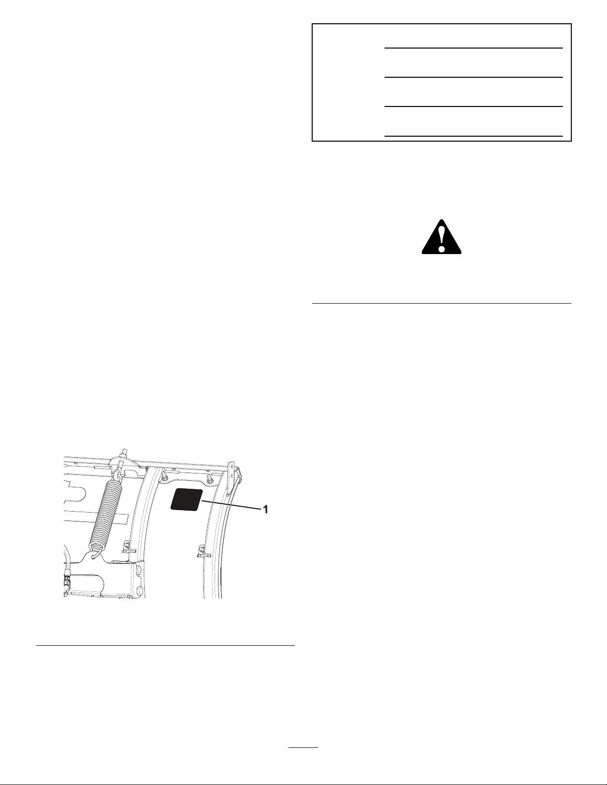
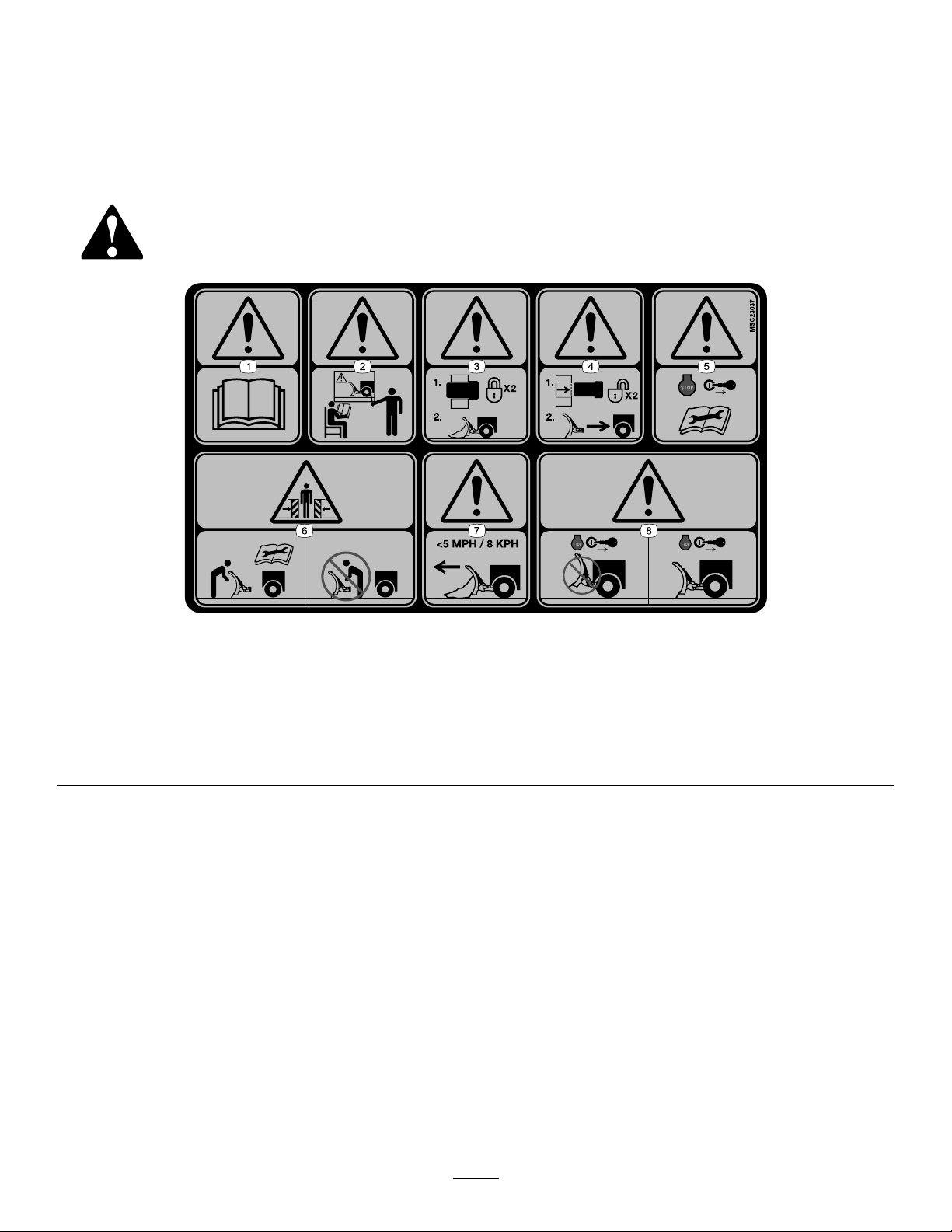
SafetyandInstructionalDecals..........................4
Setup........................................................................5
MountingthePlow..............................................5
ProductOverview.....................................................7
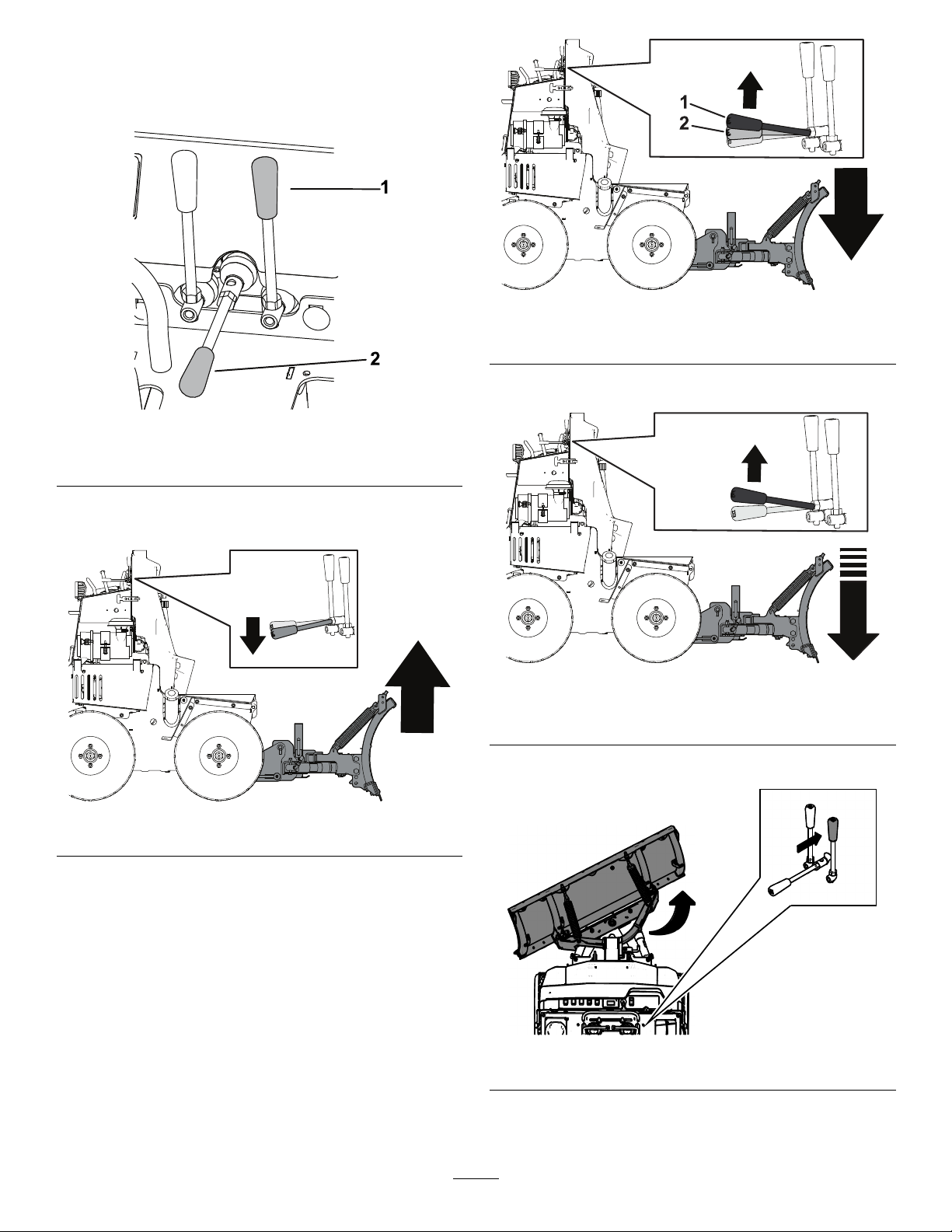
Controls.............................................................7
Operation..................................................................8
MountingthePlow..............................................8
RemovingthePlow.............................................8
OperatingTips...................................................8
Maintenance...........................................................10
RecommendedMaintenanceSchedule(s)...........10
.........................................................................10
MaintenanceSafety.............................................10
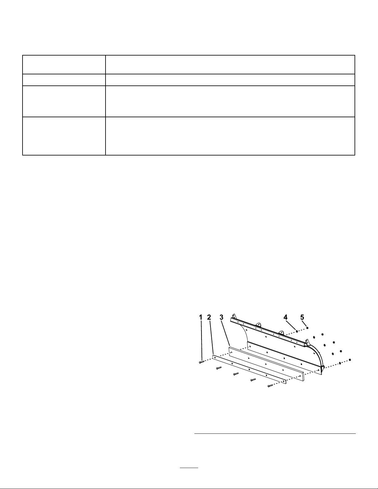
ReplacingtheCuttingEdge..................................10
.........................................................................10
Storage....................................................................11
StoringthePlow................................................11
RemovingthePlowfromStorage.......................11
Troubleshooting......................................................12
Safety
Improperuseormaintenancebytheoperatoror
ownercanresultininjury.Toreducethepotential
forinjury,complywiththesesafetyinstructions
andalwayspayattentiontothesafety-alert
symbol,whichmeans:Caution,Warning,or
Danger—personalsafetyinstruction.Failureto
complywiththeinstructionmayresultinpersonal
injuryordeath.
Preparation
•ReadtheOwner’sManualbeforeoperatingor
servicingtheplow.
•Ensurethatonlytrainedpersonnelinstallsand
performsmaintenanceontheequipmentand
hydrauliccomponents.
•Alwayswearappropriatepersonalprotective
equipmentwhenloading,unloading,andservicing
theplow.
Operation
•Usea500kg(1/2ton)minimumliftingdeviceto
moveheavyplowcomponents.
•Donotexceed8km/h(5mph)whileoperating.
•Neverputanypartofyourbodybetweentheplow
andthevehicle.
•Wearappropriateclothing,includinghearingand
eyeprotection,protectivegloves,andsubstantial,
slip-resistantfootwear.Tiebacklonghair,secure
looseclothing,anddonotwearloosejewelry.
•Whentransportingtheplow,ensurethatitis
properlysecured.Instructionsareavailableat
www.bossplow.com.
•Whentransportingthevehicle,positiontheplow
soasnottoblockyourvisionorheadlights.
•Donotchangethebladepositionwhentraveling.
•Alwayslowerthebladewhenthevehicleisnotin
use.
•Donotoperatethemachinewhileill,tired,or
undertheinuenceofalcoholordrugs.
•RefertotheOwner’sManualforproperparking
procedures.
•Turnthevehicleandplowoffbeforelling,
servicing,orcleaningit.
•Donotclimbintoorrideontheplow.
•Keepyourhands,feet,andclothingawayfrom
movingpartsandmountingpoints.
•Useyourfullattentionwhileoperatingthe
machine.Donotengageinanyactivitythat
3

causesdistractions;otherwise,injuryorproperty
damagemayoccur.
•Donotoperatetheplowwithin8m(25ft)of
bystanders.
SafetyandInstructionalDecals
Safetydecalsandinstructionsareeasilyvisibletotheoperatorandarelocatednearanyarea
ofpotentialdanger.Replaceanydecalthatisdamagedormissing.
decalmsc23037
MSC23037
1.Warning—readtheOwner’sManual.5.Warning—shutofftheengine,removethekey,andreadthe
Owner’sManualbeforeperformingmaintenance.
2.Warning—alloperatorsshouldbetrainedbeforeoperating
themachine.
6.Crushinghazard—donotstandbetweentheplowandvehicle
duringmaintenance.
3.Warning—couplermustbelockedbeforeplowing.7.Warning—donotexceed8km/h(5mph)whenplowing.
4.Warning—couplermustbeunlockedtoremovetheplow.8.Warning—lowertheplowwhenthevehicleisnotinuse.
4

Setup
MountingthePlow
1.Parkthemachineonalevelsurface.
2.Ensurethattheplowissittingupright,withthe
kickstandloweredandlockedinplace.
g370736
Figure3
1.Kickstandspringpin
3.Pullthecouplerpinsoutwardandrotate90°to
lockinthedisengagedposition.
g373475
Figure4
4.Makesurethatthehydraulichosesdonotblock
theplowattachmentpoint.
5.Startthemachine.
6.Slowlydriveforwarduntilthecouplermeetsthe
plowhooks.Raisethecouplertohookitonto
theplow.
g370673
Figure5
7.Rotatethecouplerpin90°sothatitengages
withtheplowassembly.
Note:Ensurethatthecouplerpinalsoinserts
throughtheholeinthepinchannelontheplow
coupler.
g373477
Figure6
8.Lowertheattachmentcoupleruntiltheplow
restsontheground.
9.Shutoffthemachineengine,waitforallmoving
partstostop,ensurethattheparkingbrakeis
engaged,andremovethekey.
10.Routethehydraulichosesfromtheplow,through
thehosestrap,tothemiddleconnectionson
themachine.
5

g370668
Figure7
11.Raiseandlockthekickstand.
12.Startthemachine.
13.Usethecontrolstomovetheplowinall
directionstocyclethehydraulicuid.
14.Lowertheplowandshutoffthemachine.
15.Checkandllthehydraulicuid;refertothe
machineOwnersManual.
WARNING
Hydraulicuidescapingunderpressure
canpenetrateskinandcauseinjury.
•Ifhydraulicuidisinjectedintothe
skin,itmustbesurgicallyremoved
withinafewhoursbyadoctorfamiliar
withthistypeofinjury.Gangrenemay
resultifthisisnotdone.
•Keepyourbodyandhandsawayfrom
pinholeleaksornozzlesthateject
high-pressurehydraulicuid.
•Usecardboardorpapertond
hydraulicleaks.
•Safelyrelieveallpressureinthe
hydraulicsystembeforeperforming
anyworkonthehydraulicsystem.
•Makesurethatallhydraulic-uid
hosesareingoodcondition,and
allthatthehydraulicconnections
andttingsaretightbeforeapplying
pressuretothehydraulicsystem.
6

ProductOverview
Controls
g370669
Figure8
1.Anglelever2.Attachmentcouplerlever
•Usetheattachmentcouplerlevertoraise,lower,
oroattheplow.
g381637
Figure9
g381636
Figure10
1.Float2.Lower
Note:Donotplowforwardindownforce.
g381947
Figure11
DownForce
•Pushorpulltheanglelevertoangletheplow.
g374605
Figure12
7

g374608
Figure13
Kickstand
g370736
Figure14
1.Kickstandspringpin
Thekickstandkeepstheplowuprightforeaseof
mountingandstorage.T oraiseorlowerthekickstand,
pullthekickstandspringpinandmovethekickstand
tothedesiredposition.Releasethespringpintolock
thekickstandinplace.
Operation
MountingthePlow
RefertotheMountingthePlow(page5)section
above.
RemovingthePlow
1.Stopmachineonalevelsurface.
2.Lowertheplowuntilthecuttingedgeis2.5to5
cm(1to2inches)fromtheground.
3.Shutofftheengine,waitforallmovingpartsto
stop,engagetheparkingbrake,andremove
thekey.
4.Disconnectthehydraulics.
5.Lowerandlockthekickstand.
6.Pullthecouplerpinsandturnit90°untiltheplow
isdisconnectedfromthemachine.
g373484
Figure15
7.Startthemachine,lowertheattachmentcoupler,
andslowlybackawayfromtheplow.
8.Arrangethehydraulichosesanddisconnectsso
thattheyarenotrestingontheground.
OperatingTips
•Becomefamiliarwiththeareayouareplowing;
hiddenobstructionssuchascurbsandpipescan
damageyourplowormachine.
•Donotletsnowaccumulate;alwaysplowwiththe
storm.
•Lowertheplowwhennotinusetopreventpossible
injury.
•Alwaysplowatasafespeedincaseyouhithidden
obstructions.
•Whentransportingthemachine,donotblockyour
visionwiththeplow.
8

•Donotchangetheplowpositionwhileplowing.
•Ensurethatthekickstandisraisedbeforeplowing
topreventdamagetotheplowormachine.
•Formoreplowingtips,visitwww.bossplow.com.
9

Maintenance
RecommendedMaintenanceSchedule(s)
MaintenanceService
IntervalMaintenanceProcedure
Aftertherst2hours•Tightenallhardware.
Beforeeachuseordaily
•Checkthehydrauliccylinders.
•Checkthehydrauliclinesandhoses.
•Checkallfasteners,pins,retainers,nuts,andbolts.
•Checkthecuttingedgeforwear.
Beforestorage
•Lightlysandandusetouch-uppaintonpaintedareasthatarescratched,chipped,
orrusted.
•Greasethehydrauliccylinderrods.
•Lightlysandandusetouch-uppaintonpaintedareasthatarescratched,chipped,
orrusted.
MaintenanceSafety
•Checkthehydrauliclinesandhosesdailyfor
leaks,kinkedlines,loosemountingsupports,wear,
loosettings,weatherdeterioration,andchemical
deterioration.Makeallnecessaryrepairsbefore
operating.
•Checkthehydrauliccylindersdailyforleaks,rust,
orpittingontherods.Makeallnecessaryrepairs
beforeoperating.
•Checkthecuttingedgedailyforwear.Ifthecutting
edgeisworndowneitheriporreplaceit.
•Checkallfasteners,pins,retainers,nuts,andbolts
dailytoensurethattheyaresecure.T orquethem
totheappropriatevalueiftheyareloose.
ReplacingtheCutting
Edge
Note:Replacementhardwareisavailablethroughan
AuthorizedBossDealerorBossTechnicalService.
1.Removethebolts,washers,toplocknuts,and
metalstrapsecuringthecuttingedgetothe
bottomoftheplow.
2.Flipthecuttingedgeover.
Note:Ifthecuttingedgehasalreadybeen
ipped,discarditanduseanewedge.
3.Securethemetalstrapandcuttingbladetothe
plowusingthepreviouslyremovedhardware.
Note:Donottightentheboltsandlocknutsat
thistime.
g334230
Figure16
1.Carriagebolt(1/2inch)4.Washer(1/2inch)
2.Metalstrap5.Toplocknut
3.Blade
4.Slidethecuttingbladesothatitisushwiththe
sidesoftheplow.
10

5.Tightentheboltsuntiltherubberbeginsto
squish.Storage
StoringthePlow
1.Drivetheplowtoyourstoragelocationand
removetheplow;refertoyourmachine
Operator’sManual.
2.Greaseanyexposedmetalonthehydraulic
cylinderrods.
3.Lightlysandandusetouch-uppaintonpainted
areasthatarescratched,chipped,orrusted.
4.Loosenthetripsprings.
RemovingthePlowfrom
Storage
1.Checkthetorqueofallfasteners;tightenas
necessary.
2.Checkthehydrauliclinesandhosesforcracks
orleaks.
3.Checkthecuttingedgeforwear.
4.Tightenthetripsprings.
5.Lightlysandandusetouch-uppaintonpainted
areasthatarescratched,chipped,orrusted.
6.Attachtheplowtothemachine;refertoyour
machineOperator’sManual.
7.Movetheplowthroughitsrangeofmotionto
checkthehydrauliccylinderrods.
11

Troubleshooting
ProblemPossibleCauseCorrectiveAction
1.Acylinderorhoseisbad.1.Checkthecylinders,hoses,and
allttingsforleaks.Tightenloose
connections.Replaceanydamaged
components.
Theplowangleswhileplowing.
2.Thepressurereliefvalveisbad.2.Checkthepressurereliefvalve.Ifthe
valveiscontaminated,cleanorreplace
it.
1.Thehydraulicuidlevelislow.1.Checkthehydraulicuidlevel;referto
yourSnowRatorMagOwner’sManual.
2.Theincorrectcontrolisbeingused.2.Ensurethatthequickdisconnectsare
connectedtothecorrespondingcontrol
lever.
3.Thepressurerelievevalve,onthe
machine,isbad.
3.Checkthepressurereliefassembly
onthemachine.Ifthevalveis
contaminated,cleanorreplaceit.
Theplowdoesnotangleoranglesslowly.
4.Acylinderorhoseisbad.4.Thoroughlycheckthecylinders,hoses,
andallttingsforleaks.Tighten
anylooseconnections.Replaceany
damagedcomponents.
1.Thehoseisbad.1.Checkthehoseforleaks.Tighten
anylooseconnections.Replaceany
damagedcomponents.
2.Thecylinderisbad.2.Replacethecylinder.
Oilleaksfromthehydrauliccylinders.
3.Thecylinderrodispitted.3.Polishtherodwithsteelwool.Replace
thecylinderifthepittingistoobad.
12
This manual suits for next models
1
Table of contents
Other Boss Snowplow Snow Blower Accessories manuals