Cub Cadet 190-401-100 User manual

Owner's
Manual
lmportant:
Read SafeiY Rules and
lnstructions Caref ullY
Thank you for PUrcnaslng an
American built Product-
CUB CADET CORPORATION
PRINTED IN U.S'A'
CLEVELAND, OHIO 44136
FORM 17042 - 1 (11 4.88)
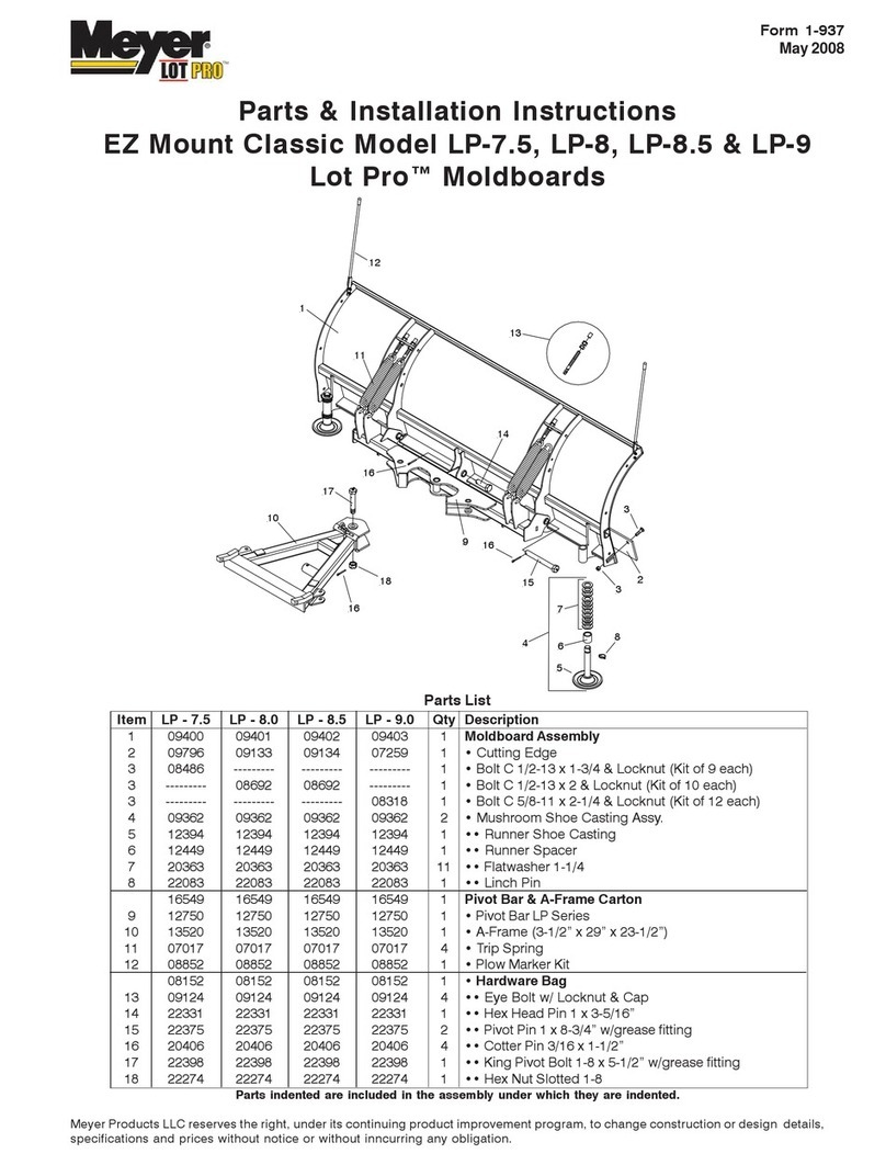
54" sNow
DOZER BLADE
SETTING UP
INSTRUCTIONS
and PARTS LIST
Model Number
190-401-100
. P.O, 8OX 36900 .

TAELE OF CONTENTS
sET-Up.... . . . . . . . . . . . . . . . . . . . . 3-8 oPr I orAL :qu I PllENT. . . ' . ' . ' . ' . ' . . ' ....'..I3
oPERrrTi0l{ lNsTRijtl!0N,.,........9-l:l R€PAIR PAaTs. .... .'"'lrr-15
!i]RK SAFELY . FOLLOV THESE RULES
Inscruct;ons given vrith this symbol
are for personal sa*ety. Be sure
you and your workers follot, them.
l,1iiuse o. niodification of th;s nachine
- $echar ical breakdown,
- prorre.tvr damage,
- inj ury ar death,
Knolr hovr to use the controis and how to
stop qL!ckl;r- Read the tractor and
i inp I enent oPerator's manuals thoroughly'
Do noi operate the equiFment whi le
\^/ear in.J loose clothing such a5 a scarf'
whic. nry bc Larght in the rot.rting
oar:s of l1e nlchine Wear sturdy
iootwear o' thc Lype ".rlrich v/ill inprove
footing on sl iPPerY surfaces'
After servicing, be sure al I tools,
parts or servicing equiprnent are removed
f rom the nrach i ne.
Thoro'Jghly insPect the area where the
blade is tc be uaed and renpve al I
objects which riight cause per3onal
inj ury of damage.
careixl I v supervi5e inexperienced
DUR IIiG OPERATIOI'i
Children sholrid not be al lob/ed to operate
the blade unless properiy supervrsed'
and are physically and mental ly caPable
of safe operation.
N0 RIDtRSI To Preveni injurY, do not
carry passerge!-s or give rides. 0nly
the operator shoold ride on the tractor
and only in the seat.
When operaiing the blade be sure you are
in the aperatorrs area, sitting on the
seat uniil the oPeration i5 complete'
Loo\ o'hird t-d-ro' beFore becLi_g
c-;ia."- n.,y un uo u -oEiced Dehi'd
START I NG
CAUII0N! Before hand I ing ANY
equ;pflenr, READ the 0PERAToR I s
I,1ANUAL.
Avoid overturns - Do not clear snow
across the face of slopes, Exercase
extrenre caution when changing direction
on slopes. Donrt attemPt to clear
s teeP slopes.
Never operate a tTactor at high transport
speeds on sl ippery surfaces, operate
the tractor snloothly - avoid erratic
operation and excessive speed. Always
ma i ntai n control .
Keep the blade in the lowest possible
position when changing the angle,
reversing, or removing the blade. Be
sure that your feet are not under the
blade vr'hen the adjustnents are made.
No person should be allov,/ed near the
working drea when the blade is being
Check overhead clearence careful iy
before driving under I oL\, hanging tree
branches, or othel situations tJhere the
opeTaior may be struck or pul led fron
the t rac!o r.
Reduce sPeed when traveling on rough
roads, sharP turns, and down 5teeP
hills,
Do not stoP or start suddeilly t'vhen
going uphili or downhill to prevent
loss of cont ro I .
Stop, shut off engine and inspect for
danrage after striking an object. RePai r
any damage before restarting and
operati ng the mach ine.
Do not overload the machine caPacity by
attempting to clear snow at too fast e
rate. Take the time to do the iob in a
Never operate the blade uithout good
light or visibilitY.
No one should operate the machine while
intoxicated or while taking medication
f-at iapair> the senses or reactiors.
BE FORE
-2-

Cub Codet CotPo.oti@'s P.omi* To You
We p.onise you, the fasr vser Pulchose!, rhdt we wiLl
reoldce or repoir oiy port or Porls of yo.t r'^ ouldoor
power producl wlich i5 d"lecli"e i. moleriol o-
wo.kmonship without chorge for eiiher Pdrts o. lobor
durins rhe firsr yeor following delivery ro you
We olso promise you, the first user plrchoser, o second
y"o. ro.ionty od rhe engine ond drive iroin of vour new
Clb Coder Trocior. Lown Tlocior or Riding I rocio!.
Whot lhe *.ond yeor cove.s
(A) Ir will cover the ensine inre.nol Poris contoined
wlthin rhe ensine shielding excepr fo. poinrs, condensets,
spork plugs, oir filtert ond routine mointenonce Porrs.
iB) Ir will cove. the t.octor drive troin including drive
it'o*., a"ru. shofr clurch, oll ports enclosed bv tlons-
mirri;r housino, ond orle hoLsinq, o"le chofls, findl
drives, rpindle ptlley3, spinole beorings, ond eleciri. PTO
Horc Moinrenonce Products: We Promise vou, the firsr
u'er ourcl'oser, o I vedr dorrontv on oll Ho-e
Mcinteronce Producrs. tnis will cover Push Mo-ers, Sel'
Propelled Mowert Uriliry T!oile!t Wolk Behjnd Tillers,
chore Pe.formers ond Snow Throwers
The Tecumseh ensine, used on Wdlk Behind Snow
Throwers, will corry o 2 yeo. worlontv or the engtne
Cub Codet Attdchmenrs:
We promlse yo!, the fi.st use. Purchoser' thdt we wiil
reolice "r reiol. ony Pori o. Port5 which ore defecrive in
mi:teriol or worl<do.shiP witho!r chorse for poris or
ldbor dur:no '\< firsr veor folloxing deliverv ro you'
Thi' .ilr cr;er oll Cub Codet attochme'l< This does not
tnclude Approved Allied Equipment which is sold ond
worronied dnecrly by the monufdcturer.
Obtoliiig Worroniy Seryice Thrdgh Cub Cdd€r Deolers
Worronty .epoi.s will be mdde by vou! sellins Cub Codet
dJ;; ;" .;y cub Coder deolei outho.izied io sell rhe
rvoe o{ equip+enr invol ed durl'g tr'( r'(r-ol horki'g
hijurs o' ttie deolcr sF'vice d-portm-n. YaJ, th- pJr
choser, ore .esponsible for rronsPoriotion of ihe
eouiDment to the deolelship for worrdnrv service or fo'
ony service coll exPense, olong wiih onv 6v€'iime lobo'
Reploement Potts WGrontY
Cub Coder poris which ore furnished dnd insrdlled !nde'
*'1. -*-.iv ore rhemselves within rhe coveroge of rhis
worontv foi the dutoiion of ihe orjginol wo'rontv Period
- i.. '"i""ty ddys olrer insrollotion, whichever period
Whor is rcr Cove.ed
Taes ord tubes ore not covefed by rhG woffonry, bur o.e
worronted by their monufocturer. Regulor doinrenonce
replo.emeni items such os sgork plugs. ignition poinrs,
cordensers, belrs, c!ttins porrs, filte.s ond lubricontt
ond moinrenonce odj!stfrerts s!ch ds fuel sysrem cleon-
irs, engine iure-!p, broke ord/or clurch in3pecrlon or od-
jusimeni, when s!ch replocement or odjusrments ore
mdde os port of no.mol moinrenonce service are excluded
from coverqge. Any non-Cub Coder prodlct which you
moy hove insrolled in or upon the plodld is ol3o .x-
No pe'<o. is ou-horized ro giv_ ory o'5er worro.ty ot ro
ossJ-e ony orhe, liobilities or ll^. Conpony's oe.olf Jn-
less mode or osslmed in wriiing by rhe compony, ond no
perron is ourhorized ro giv" o_y worronties
;iy liobili'ie, or rae selle, * behol' u.less tode or oe
sumed jn writing by rhe seller.
Limitotions On Our Responsibility
Pleose cd.efully nofe thot this is o two-woy og.eement.
We p.omise to moke free repoirs o. repldcements os
stored, bu' yo- oglee, lhol e'cePr for our obligorion to
-o(e gooo o- -1is promi.e, we sLoll noi be ,esponsible
fo. ony expenses or i.converience which you mishi incur
d expdience with respect to ou. prodlct, ror sholl we
be lioble for defeck, domose, or foilures colsed by unou-
ihorized olterorionE urredso.obie use, occident ot obuse,
incl-di_q loilure lo p,o";de reoso'soble ond .eces5or/
mo:"re.;.ce, ofler o-r produd hos been d'livered -o vou.
Some sroies do ror ollow rhe exclusion o! lim oiion of
incidenrol or consequeniiol domoges, so the obove limiio_
tion of exclusion moy nor opPly ro you. This worronty
sives yo! specific legot lights, ond you moy olso hove
orher righis which vory from stoie io stote.
The foregoing pordgrqphs consiiiute Cub Codet CorPoio-
tion's enaae tiorranty wirh respe.t to ony P.oduct Pu-
chosed ond used for personol, fonily, or household PUr-
poses os di3iinguished from commericlol !soge.
All Cuo Codei p,odrcts .i1l ,e worro^ied ogoinsr defec-
live DoLrs or worL-o..Lip. Thi. i. for CLo Coder Troc-
tor, Afiochnents ond Home Moinrenonce producr3 ond fo!
THIS WARRANTY IS IN LIEU OF ALL OTHER WAR-
RANTIES, EXPRESSED OR IMPLIED. WARRANTIES OF
MERCHANTABILITY AND FIlNESS FOR PARTICULAR
PURPOSE ARE EXCLUDED, AS ARE ALL OTHER
REPRESENTATION TO THE USER.PURCHASER, ANO
ALL OTHER OBLIGATIONS OR LIABILITIES, INCLUD-
ING LIABILITY FOR INCIOENTAL AND CON.
SEQUENTIAL DAMAGES, ON THE PART OF THE
COMPANY OR THE SELLER,
SAFETY RULES
IJo not run the engine in confined areas
such as storage buiidings any longer
than is necessarv. Move the tractor
o!tside into the air. EXHAUST GASES
ARE ToXlC, opening doors and windows
may not provide adequate ventilation.
Be careful to avoid catching the blade on
stumps or other immovable objects.
TRAN SPORT I NG
Be sure that the blade is fully raised
and is in the straight forward position
when in transport.
When turnins close to buildings or
passing through narrow areas, be Sure
to allow sufficient clearance for the
blade.
(CONT I NU ED )
AFTER OPERATING
Always l\,ait for the tractor to come to a
complete stop, lower blade to the
ground and shut off the engine before
leaving tractor,
To reduce the possibil ity of unattended
movement of the tractor or its use by
unautor i zed operators which could
result in an accident and injury, shift
transmission into neutral, set the
parking brake, stop the engine, and
remove ignition key when leaving the
mach ine urattended.
SET UP
,G. q
-*.---\-
-e----L-.{
.. *-G
_-;;F
c---------- o "
I
\rL f]
Fis. I
UNPACK ING
Your dozer blade and al I necessary parts
are packed in two cartons. Unpack the
cartons cdreflrlly to insure that all parts
The dozer blade attachment consists of the
foilowing: (see Fig. I )
A. Pivot Box 6 "AI Frame Assembly
B. Rear lieuntinS Frame Assembly
l. Front llount i ng Frame
D. Lift Bracket Assernbly
:. P;vot Cortrol Arm
r. Ltrt tuoe
G. Pin Release Rod
H, Pivot Control Rod Front
J. Pivot Control Rod Rear
K. Pivot Control Handle
L. Bag of Pa rts
M. Dozer Bl ade
N. Anchor Piates
Tools need€d for assembly are as fol lov./s:
l. 3/4" Box End l,/rench , ' , . . . . . . . . ' . . 2
- 2. Large Pair of P I i e r s . . . . . . . . . . . , . l
-J-

SET UP
PREPARAT ION OF TRACTOR
Before instal !ing dozer blade remove any
cther attachnrents i'hich may be on tractor'
washe r to trac!or
t (R) , spacer (N) and
t ractor frame (See
wi th heavy d uty
acer (N) and
I NSTALLI\T ION OF ANCNOR PLATES TO TRACTOR
Asseirble anchor plate !o each side of
tractor using t!.ro 3/8" hex bolts \!ith Iock
r.rashers and nuts, and one l/2" hex bolt
with lock washer and nut. Al I are found
in bag of parts .
l. Assemble anchor plate (A) to tractor
frame (8) with two bolts (C) with
lock washers and nuts, and one bolt
(D) r,,rith lock lrasher and nut. (see
2. I rq. J,
Secure bolts tightly, then assemble
other anchor plate (A) to opposite
side of tractor in the same manner'
Assen'L le heavy dutY
I 0 isassemb le bol
washe r (P) froir
Fis.2)
?. Rep l oce trscaor
itas her fouNd ir
3. Reas semb I € bol t
new rvasher (PJ (e) , sp
INSTALLATION OF ''A'' FRAI4E ASSEMBLY TO OOZER
BLADE
Assemble "A" frame assembly to dozer blade
with locating pin, two washers and two
cotter pins. (Found assembled in dozer
blade)
l. Lay dozer blade
tSee Fis.4)
2. Sl ide rrAr frame
on dozer blade
l. 41 ign holes and
th rough
4. Secure locating
(M) w ith cotter
(fi) face down on ground'
assemb ly (A) into pocket
(l]ia. ro"",r"g pin (N)
pin (N) to dozer blade
pin {Q) .
-4-

SET UP
INSTALLATION OF PIVOT COI{TRCL ARI4 TC REAR
MOUNT I?{O FRAHE ASSEMBLY
Asieriible pivot control affr to rear mounting
assernbly vrith two cotte!' Pins found in bag
t. Assemble pivot controt arm (E) to rear
rountinq irame (B). (see Fi9 6)
2. Secure with two cotter Pins (N).
INSTALLATION OF TILT SPRINCS TO OOZER BLADE
Assenble springs to doler blade using
specidl hook furnished \dith unit.
L Place dozer blade (H) uP right on
ground. (See F ig. 5)
2. Assemble four sprinqs (R) to spring
anchor (S).
3, Uslng special hook (T) Place foot on
- dozei btrde (Ai strerch sPring (R) and
hook it into hole on toP of doler
biade (A) '
INSTALLATION OF FRONT MOUNTING FMME' REAR
MOUNTING FRAIE AND DOZER BLADE
Assemble tront nounting freme and rear
r,lount ina frame to dozer blade using two
washers and one cotter Pin found in bag
of parts,
NoTE: set unit o.' 2 x ! bo3rd apProximately
12" long for this oPeration in setup.
(tee rrq. /,
l. Piacc iront mounting frame (C), rear
mounting frame (B) and dozer blede (M)
together as s hov.rn in Fig. 7.
Assemble washer (P) onto I ift arm
assembly (D),
Si ide I i ft arB assembly (D) through on
s ide.
Assemble bel I crank (q) onto I ift arm
assembly (D) with short leg to inside
sl ide I i ft arm assenrbly (D) through
other side of frernes.
Secure v{ith washer (P) and cotter pin
(R).
2.
3.
4.

SET UP
FIG. 8

t.
Asse.ible rear pivot rod to dozer with two
hair cotter pins found in bag of parts.
I . Secure bel I crank (Q) to I i ft bracket
assembly (D) \"rith cotter pin (R).
(see F ie. B)
2. Assemble rear pivot rod (J) under rear
moln t ing frame assembly (B),
3. Assemble rear p;vot rod (J) to bel I
crank (Q) and secure !rith hai r cotter
Pin (s).
4. Assemble rear pivot rod (J) to pivot
control arrn (E) and secure with hair
cot te r pin (T) .
I NSTALLAT I ON OF FRONT P IVOT ROD
Assemble front pivot rod to tractor with
two hair cotter pins found in bag of parts.
IIISTALLAT ION OF REAR P I VOT ROD
Assemble rear pivot rod to dozer with tlro
hair coLt'- pi . 'o-no i. bdg or pa-rs.
Assemble hooked end of front pivot rod
(H) to "n" frame assembly (A) and
secure with hair cotter pin (U). (See
Fig. 8 e 9)
2. Assemble threader end with anchor of
front plvot rod (H) to lel I crank (Q)
and secure with hair cotter pin (V).
INSTALLATION OF PIN RELEASE CABLE
I Place pin relea:e cable (\r) under lift
bf€cket ar:embly (D) and over rear
rnounrinS franc (B). (Se. Fis.8)
2, Asserirble hook of pin release cable (vJ
i nto hole ;n end of pivot strap (X) .
INSTAL LAT ION OF PIN RELEASE ROD
Assenble pin release rod to pivot slrap
,-,irA ^.a hri..^rr6r ^i. {^.i./.1 i- l-i^
t.
SET UP
INSTALLATION OF DOZER BLADE TO TRACTOR
Assemble dozer blade to front of tractor
using two hex bolts, two flat washers, and
two lock washers found in bag of parts.
Assemble dozer blade to rear of tractor
using one locatinE pin found loose, and ro
hair cotter pins found in bag of parts.
l. Roll tractor over dozer blade rear ntg.
frame (B),
2, Lift up on front mtg. frame and snap
into t ractor quick hitch.
3. Secure front mounting frame (C) to
tractor with bolt, flat washer and
lock was_er \' l. \>ee 'rq. ru/
4. L ift rear of mount ing frame (B) to
align holes of mounting frame with
holes in anchor plates (A). (See Fig. ll)
5. Slide locaiing pin (E) through holes
in anchor plates and mounting frame.
6. Secure locating pin (E) !rith hair
cotter pin (F) at each end.
Assenble threaded end !rith anchcr of
oi- rele":i 'od (L) Lo pi/oL sLrdp (Xl.
(See F is. Bl
Secure \!;th hnir cotter pin ((). -7-
2,

$ET-UP
SECURE P IVOT CONTROL ARI4
To secure pivot contaol arm to dozer frame
use one coLter pir found in hag of Parts.
l. Pull pivot control arm (E) as far to
the right hand side of tractor as
possible. (See Fig. i2)
2. Secure with cotrer pin (N).
INSTALLATiON OF .'iVOI CONTROL HANOLE
l. Siide pi\./ot control handle (K) over
pivo- conrrol arr (E), (see cia. lJ)
I NSTALLAT ION OF P I N RELEASE ROD TO P IVOT
CONTRO L HANDLE
Assemble pin release rod to pivot control
handle v/ith one hair cotter pin found in
bag of pa rts.
l. Assemble pin release rod (G) into hole
on pivot control handle (K) . (see Fig.
t3)
2. Secure !./ith hair cotter pin (P).
INSIAL LAT ION OF LIFT TUBI
Assenrble I ii. tlbe useing two washers
and two hair coEter pins found in bag
I " Assenble I ift tube (F) onto tractor
I ift bracket (Z) and secure with
washer (X) and uiih hair cotter pin
(Yi. (see r is. l4)
2. Assernble I ift tube (F) onto I ift
bracket 6ssembly (D) and secure
wi th washer (X) and wi th ha ir cotter
pin (y) .
-8-
F ig. l2
F;E. l4
Fig, l3

INSTALLATION OF CROSS SHAFT SUPPORT STRAP
Install cross shaft support strap using
bolt, lock washer. rJt a.d liair cotter pin
found in bag of pdrts,
SET UP
INSTALLATION OF TMCTOR LIFT KNOB
SPACER
l. Unscrew and remove lift knob (A).
2. Place I ift khob spacer (B) onto
threads of I ift knob (A). (See Fig" i48)
3. Screw I ift knob (A) back into
tractor, adjust cam stop (c) to
des i red pos i t ion ahd t ighten
I ist knob (A).
2.
ll,
Fasten cross shaft support strap (R)
loosely to tractor I ift bracket (S)
\,/ i tb bol t (T) , lock washer (U) , and
nut (V) . (see Fig. l4A)
Sl ip other end of cross shaft support
strap (R) onto peg on end of tractor
c.oss shaft lever (v)"
Secure cross shaft support strap (R)
to tractor cross shaft lever (V) rrith
hair cotter pin (X).
Tighten bol t (r), lock washer (U), and
nut (V) hol d ing cross shaft support
3htrft (Rl to tractor ] t bracket (S).
ih'
'-)'?
'u
Fis. l4A Fi9. l4B
- 8A-

OPERATIOIU
OPERATING INSTRUCTiONS
The blade is de5igned for use on lnterna-
rional Cub cadeL Trac )rt for clearirg
snow, leveling sott dirt or 5and, and
other lightweight dozer jobs. Ths spring
trlp release Protects the blade, tractor'
and operator from severe shock loads when
the blade comes in cont3i:i r'rith curbs and
other obgtaclea, regaidiess of spee'1. The
blade has a teversible and repleceable
cutti n9 edge.
BEFORE PLACINC DOZER BLAOE INTO CPERATION:
l. Check all bolts End nuts lor proper
tightness and al I parts Ere assembled
proPer I y.
2, Test the fcl iovrlng con:rols for smooth
operat ion.
A. Li ft control iever
B, P ivot control handle
A
e
IICTE: Ternrs left and ri
manual refer to the left
of the dozer biaie lthen
rear of dozer blade.
TO RAIST AND LO\,/ER UOItIt ELAUE
Lift control lever (A) to raise and lower
dozer blade is located on left hand side
of tractor dash. (see Fig. i5)
To raise dozer blade, pull back on lifi
contrDl lever until desired height is
reached,
To lower dozer blade, Push forward on I ift
coniTol lever until dozer reaches desired
he igli t,
TO ANGLS DOZER BLADE
The manual !y operateci dozer blade has five
angular positions. The angle is controlled
by the pivot control handle (B).
To anqle dozer blade to the right' twist
pivot control handle (s) counterclock-
wise and pull rearward. vhen desired angle
is reached turn Pivct control handle clock-
!.rise to lock dozer blade in Place.
To angle dczer blade to the left, twist
Divot control handle (B) and push forward
ilhen desired anqle is reached turn pivot
control handle clockwise to lock dozer
blade in place.
ght as used in this
and right sides
fac ing forward frofil
LO\,/ER DOZER BLADE
--9-

OPERATION
OPTIONAL EqU IPHENT
HYDRAUL IC ANGLED BLADE ATTACHMENT
This atrachment (KIND 006-coDE 3247) is
provided for hydraul ic angl in9 of the
lnternational 54-inch front mounted dozer
blade on lnternational Cub Cadet Hydrostatic
DTive tractors equipped with front hydraul ic
outlets.
PUSH I NG SNOV
Uhen pushing snow adjust the skid shoes so
the blade cutting edge just clears pave-
ment and remove two of the four tilt springs
oh dozer blade,
LIFT GRAD ING
When light grading and spreading soil, sand,
gravel etc. Adjust the skid shoes so they
are even with cutting edge and leave ail
f,o.u r tilt springs in position on dozer
blade,
HEAVY GRAD ING
Vhen heavy grading of soil, sand, gravel
etc., adjust the skid shoes so they are
sl ightly above the cutting edge and leave
all four tilt spring in position on dozer
blade.
SKID SHOE ADJUSTMENT
The skid shoes (D), are adjustable for
raising or lowering the blade edge. |lhen
moving material on rough or uneven surfaces,
lower blade shoes thus raising the blade
edge. After adjustment, always tighten
nuts (B) securely.
For additional blade cleerance, such as;
Snow removal on uneven side\,valks, crushed
rock drive\,vays, etc., raise dozer blade
and pface a 2 x \ or some similar object
flatwise beneath each end of blade as shor,tn,
(see Fig, l7), loosen nuts (B) drop skid
shoes to ground and retighten nuts (B).
SCRAPER BLADE ADJUST}IENT
when scraper blade becomes \4ornt remove
bolt and nuts (A) turn scraper blade over
and reassemble, this wil I double scraPer
blade I i fe.
Fis. l7
r1q. to -10-

Lower the dozer blade to the ground and
Taise to transPort position once more.
Check to se€ that the adjustment is correcl.
OPERATION
Adjust the lift he;ght so that the top edge
of the 'rArr frame assembly (A) just touches
the under side of the up stop angles (N).
Hold the adjustment bolt head (q) from
turning and retighten the jam nut (N)
firmly, to lock the bolt head in Position.
TRANSPORTING
Be sure that the blade is ful Iy raised and
is in the straight forltard Position when in
transPort.
vJhen turning close to bui ldings or passing
through narrolr areas r be sure to al low
sufficient clearance for the blade.
Avoid heavi ly-traveled roads when fibving
equipment, if at all Possible.
AFTER OPERAT ING
Aiwavs wait for the tractor to come to a
compiete stop, lower blade to the ground
and shut off Ehe eogine before leavlng
t Tac tor.
"To reduce the possibility of unattended
movement of the tractor or its use by
unauthorized operators which could result
in an accident and injury, shift trans-
mission into neutral ' set the parking
brake, stop the engine, and remove
ignition key v,/hen Ieaving the machine
una ttended.
Fis. lB
DOZER LIFT AoJUSTI4ENT (See Fig. l8)
For maximum dozer blade ground clearance and
machine stability when transPorting, the rrArl
frame assembly (A)-must hit up stop angles
(N) when machine is raised by the tractor
I ift system.
Raise the dozer blade to the full transport
heiaht. chec( the clearance between the rop
of iA" frame assembly (A) and tne under side
of up stop an91e (N).
The top edge of 'rArr frame assembly (A) should
just touch the under side of the up sEop
angles (N).
lf the rAr frame assembly (A) does not touch
the up s[op angles (N) or is. forced tight
"o"intt tf'L up stoo angles (N) a lift height
"iju.tt"nt is necessary' Proceed as fol lowsi
Lo!.rer the dozer blade to the ground and
ioosen jan' nut (P) on the adjustnenl bolt
i."",.a"." the iift bra.ket assemb)y (D) at
the right side of the dozer blade'
Operrte the tracEor lift and raise Ehe dozeT
uiade to the ful I transPort height' Turn
rhe ad;usrmenr bort head ,0, '"::il1"l::," LrrBRtcATtoN
clock-wi5e direciion to raise th'
assembly (A) or clock-wise o'tutiion to rt P?:it:l::]-lv:-l"bticate the pivot points
lower the,!A', frame (A). -ll-witir a good grade of engine oil'

OPERATION
FRoNT PIVoT ROD ADJUSTMENT (see Fis. 19)
To adjust front pivot rod (H) remove pin
(V) turn anchor (z) counter-cl ockwi se to
lengthen rod and clockwise to shorten rod
The front pivot rod (H) is adjusted to th
proper Iength when rlArr frame assy. (A) wi
hit both stops (X) by movement of pivot
control handle (K). (See Fi9. l5)
PIN RELEASE ROD ADJUSTMENT
To adjust pin release rod (G) rerove hair
pin (N) turn release rod (G) clockwise to
lengthen it and counter-clockwise to short-
en it, (See Fig.20)
The pin release rod is adjusted correctly
when dozer angle lock pin (P) is flush
with the front of pin housing (Q). To
move pin forward lengthen pin release
rod. To nove pin rearward shorten pin
release rod. (see Fig. 2t)
F ig. 20
-12-

OPTIONAL EOUIPMENT
4. Run hoses under hydraul ic cyl inder
and tie to pin hsg, (S) with two plas-
tic ties (V),
5, Tie hoses together at top with plastic
ties keeping al I excess hose in "Al
frame assembly (A).
5. Assefllble male connector to eacn nose.
7. Insert short hose ihto bottom coupler
on tractor. Insert long hose into
top coupler on tractor.
NoTEI Make sure hoses do not touch any
filov ing parts.
IIYDRAUL IC ANGLED BLAOE ATTACH}.IENT
This attachment is provided for hydraulic
angl ing of lnternational 54_inch dozer
blade on International Cub Cadet Hydro-
static Drive tractors equipped \rith front
hydraul ic outlets.
l. Disassembie manual angling parts from
dozer blade (see Fig, I ) (E) , pivot
lonlrol arm (G), pin release rod (H),
pivot control rod front (J), pivot
control rod rear (t<), pivot control
handle and dozer angle lock pin (P).
(See Fi9.21)
2. Assy. hycraLri ic cyl inder (N) to dozer
blade (l{) with two pins (P) and tlvo
hair pins (q) . (See Fis.22)
Assy, hydraul ic hoses to cyl inder (N),
long hose (R) to rear of cyl inder,
short hose (l) to front of cyl inder.
Fis. 22
3.
-t3-

' eua GIDET s4' DotrER BL3rlE MooEL t'lo' 1q!'ao1-1(x)
20--:{
(.2
ta-'\s
$*
5
/ -,/ tl ,
/,*--iP'
uNi -JI
26
/
i,.t
urtt-
\
28
{
:\ l5
N(u
Fu Fu $tl S*a $o
o-l{ s-60 460 e3g Gm
J r( frI il P
t8
52
DJ
t
,"(/. ,28
ABCDET
F: h: L: HHF'
et5 @-23 939
-\2r"
i :656
-*<6\i i /
*,Y;
\h
,fy
u, --/
?lr
\e,
P
t
ti
c'
q"'
fi
E - 3055 (11.4.88)

cuB CADEI s+' oozrR .ADE M@EL NO. 19H01-100
OESCFIPIION ow. FEo
CEF, NO.
2
3
6
I
I10
11
12
13
15
16
't7
1ts
19
ZJ
2l
22
2.3
24
26
27
2a
29
30
31
32
34
36
ili
39
!2
53
54
T5
56
5A
59
60
6i
62
63
FART NUMBER
12325
12355
G[,t-i2$58r
GM.2711A4'
12356
G[l-1209151
4808
GM,27r190*
12359
G[r.120123*
qM-45615ir
12751
Glr-180177'
GM,120384!
G'i,l- 1203a9'
12754
GM-4554a1r
127f0
GM-180122*
G lv1-94 i 3$4 r
12754
GM-180175.
G1\r-l2G7A*
14294
12766
G[4-137258r
12769
3430
9492
12712
18857
12776
12869
14247
12843
12792
4570
GN4-180173'
c!1r20238r
1$46
5681
6M-110362.
1A3A?
1:i't5
3!96
12343
1:446
'12771
r43!O
Gl',i.1!ffe2"
G i?i.1203:7*
G&1-r20s96r
33n t
13354
13382
GM.9414074"
324?
11018
14297
12493
17t4'
eledeAss.mbly , . 1
Cutting Ed96 BladB. . 1
Boh -s/1e18x 1'Carlaqs . 9
liaLockwash6rtus€mbly,5/1&18H.x. . e
Skid Shoe. . . .2
Bolt"3/&1exr'Cafflage. . a
Strap ,2
Nut & Lock Wash€.l6!€mbly - 3/&16 H6x ... .4
Loearing Pin .2
Coder Pin. .1
Wssher - 13,/16'x 1n/2'x,134 Flat, . 3
Fronl Mounling frsn€ Assembly .1
Bolt"1/2-13x1-1/2'H€xHead. 12
washer - 1/2" MBdium Lock 15
Wash€r - l/?x 1-114"r.083 Flal . 4
Molnting F.am. Assembly . 1
Foll Pin. , 1
Pivot Control Strap , 1
Boll-3/&l6x l Hex Head .5
Nul- 3/&16 Hox Lock. .1
Front Mountirg Srrap . , 2
Boll- l/2-13x 1nl4 Hex Head . . I
Nut- 1/2-13 Ught Hex . 12
FBar Mounring FrameAss€mbly. . 1
Pivoi Arm Assembry. . I
cod€r Pin -3116^1 1-314'. .7
PivolBod. .1
Hah Cott* Pin . 9
Anchor, ,2
Bolt - 1l2rg x 1'Hex H€ad .2
Nut.1,/2.13 Hat Hex .2
'A Frame tGsembly. , 1
Sping . . 1
washef-21.r32 ! 1-5116 x.095 Frar .2
Pi "l Srop'r9le.
Piv6i Borr€sembly,
Pivot Conkol landl€ Assembly .
Pilot Conrrcl Cable & Lock Pi; ,ssembly . . . . . . . . . . . .
BellCrank !cs6mo'y
Pivol C,onlrol Rod A$embly
UftTubo
Ut A,m rcs.,nbly
Lrfl EiGnE:cn l€s€mbry
Bc[ .
'3 Flco,i
Tracior Uft Kno! S'jnc"l
Washer,
Aroakdver Spring . . . . . .
S.rrirg Voi l.g H. o..
Pi,cr Co.lro Pc:l
qncho. Plalo ,
w.sl.e, - V8'MediLm Lock
l.lJt I g-'dUQrlHrx.
't!as\e, r/ 12 '1-r/16 x.095 Fla!
H..r C.nv' P n
S: &2
rrcl s!. ir :Pacl'
1,r 12.rili€-Loc\
4
1
2
4
2
2
1
2
Suppo't Sl.ap.
(ior Hydra!lic A,rgle Kil)
r $..dr.td e€td*4 - Pr..ft.red LocAlly - t5 *E - 3056 (11.4.88)

Model 19O-4O1-1OO
}IOW IO ORDER
REPAIR PARTS
REPAIR PARTS
All ports listed herein moy be ordered from ony
outhorized Cub Codet Deoler.
WHEN ORDERTNG REPAIR PARTS, ALWAYS GlvE TIIE
FOLLOWTNG INFORMATION:
. THE PART NUMBER
. THE PART DESCRIPTION
. THE MOOEL NUM BE R
. THE NAME OF MERCHANDISE
Other manuals for 190-401-100
1
Table of contents