2131
.1
Checking Procedure
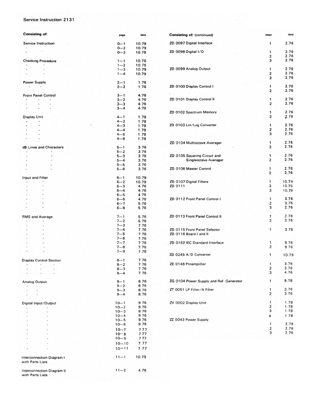
100
CenttrFrrqueiq.:
UXlk
Hz
l,ftI:l00.0
d
90
80
70
60
50
IB
40
15
18
21
24
27
JO
33
36 39
42
·W
Filter
8andwidth
Octa",
to
"1/3"
Frequency Range Hz to
"1
,
6-1.25
k"
System
Reset
Channel
Selector to
"1
.
00
kHz"
Reference: "In"
A-Weighting
:
"In"
A-
Weighting
:
"Out"'
Input
Att
. to
"30
dB" (bottom line)
A·Weighting
to
"In
"
Gain Control to ··Cal."·
A·Weighting
to "Out""
SystAm Reset
Reference: "In"
Averaging
Control
to
"Reset"'
Averaging
Time
s to " B"
System Reset
Filter
Bandwidth
Octave to " 1/
1"
6B% Confidence Level to " u = O,
5dB
"
5B% Confidence Level
10
"u
= 2 dB"
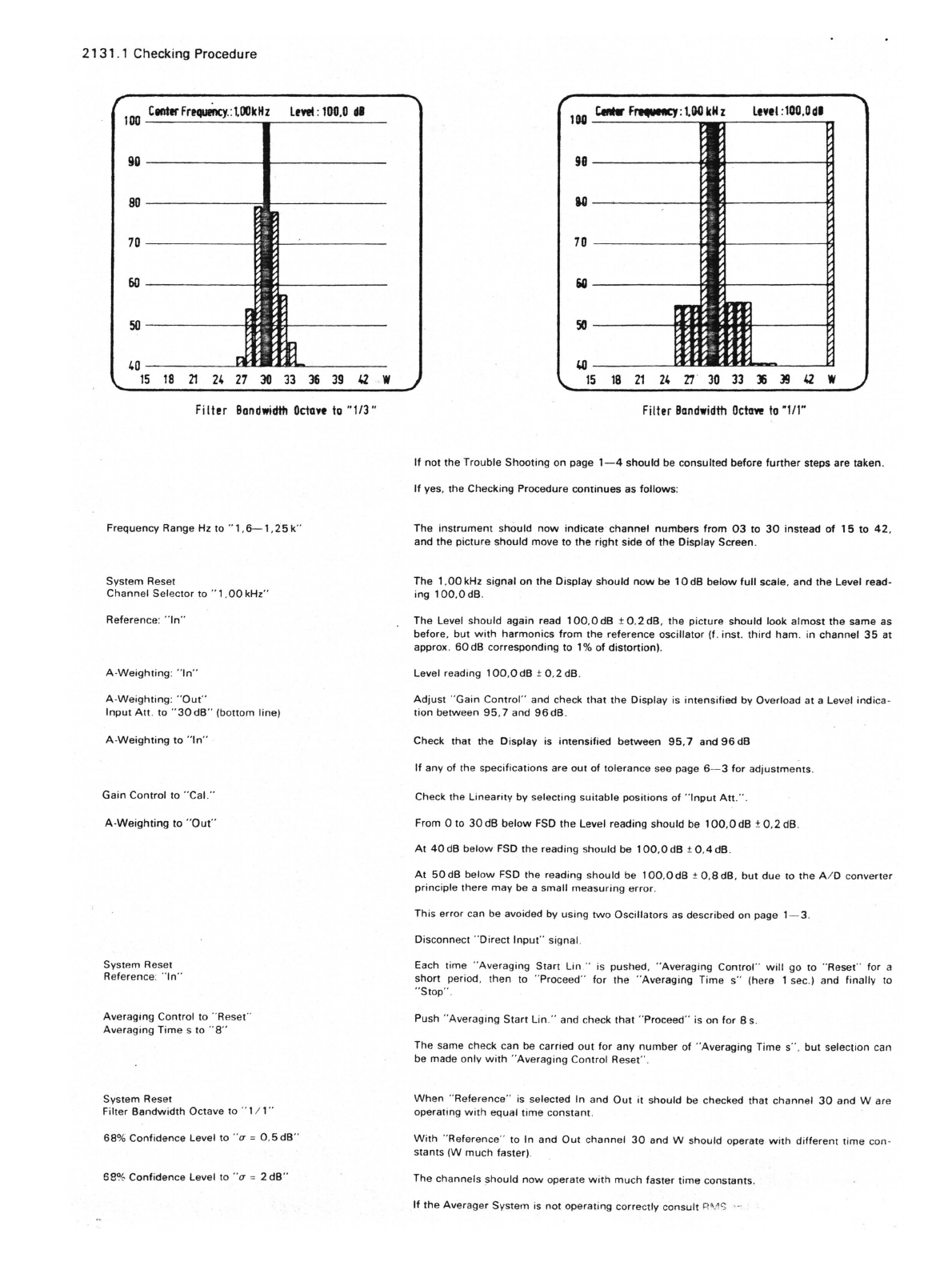
lOG
c.e.r
F,.....cy:l.00kih
l,
••
1:100,Od.
98-----------4~*---------~
U--~------_+EI__----~
70
------------~~----------~
iO------+JII>J------t1
Filter
Bandwidth
Octaw
to
"lit"
If
not
the
Trouble
Shooting
on page
1-4
should
be consulted before
further
steps are taken.
If
yes, the Checking Procedure
continues
as follows:
The
instrument
should
now
indicate'
channel
numbers
from
03
to
30
instead
of
15
to
42.
and
the
picture
should
move to
the
right
side
of
the
Display Screen.
The
1.00
kHz signal on
the
Display
should
now
be
10
dB
below
full
scale,
and
the
Level read·
ing
100.0dB
.
The Level
should
again read
100.0
dB ±
0.2
dB,
the
picture
should
look
almost
the same as
before.
but
with
harmonics
from
the
reference oscillator
(f.
inst.
third
ham
. in
channel
35
at
approx.
50
dB corresponding to
1%
of
distortion).
Level reading
100
,OdB
±0
.
2dB
.
Adjust
"Gain
Control"
and check
that
the
Display is
intensified
by Overload
at
a Level
indica·
tion
between
95
.7 and
96dB
.
Check that the Display is
intensified
between
95,7
and
96
dB
If
any of the specifications are out
of
tolerance see page
6-3
for
adjustments
.
Check the
Linearity
by selecting
suitable
positions
of
"
Input
Alt.
" .
From 0 to
30
dB
below
FSD
the
Level reading should be 1OO,OdB ±
0,2
dB.
At
40dB
below
FSD the reading should be 1OO,OdB t
0.4
dB.
At
50dB
below
FSD the reading
should
be
100
,OdB t
o.adB
,
but
due to
the
A I D converter
principle
there
may
be a small
measuring
error
.
This
error
can be avoided by
using
two
Oscillators
as described on page 1- 3.
Disconnect "Direct
Input
" signal.
Each time "
Averaging
Start
lin
" is pushed,
"Averaging
Control"
will
go to
"Reset
" for a
short period.
then
to "Proceed"
for
the
"Averaging
Time
s"
(here I sec.) and finally to
"Stop" .
Push "Averaging
Start
lin
."
and check
that
"Proceed" is on
for
Bs.
The same check can be carried
out
for
any
number
of
"Averaging Time s
".
but
selection can
be made only
with
"Averaging Control Reset
".
When
"
Reference"
is selected In and
Out
it should be checked that
channel
30
and
Ware
operating
with
equal
time
constant
.
With
"'Reference" to In and
Out
channel
30
and W should operate
with
different
time
con·
stants
(W
much
faster).
The
channels
;;hould
now
operate
with
much
faster
time
constants.
If
the
Averager System is
not
operating correctly
consult
8'.1'> ,-