Avdel Genesis G4 HD User manual
4
Druckluftgerät
Genesis®G4 HD model
Heavy Duty
Attrezzo oleopneumatico
Genesis®G4 HD
Maggiorato
Hydro-Pneumatic Power Tool
Genesis®G4 HD
Heavy Duty
Outil oléo-pneumatique
Genesis®G4 HD
Haut rendement
Instruction Manual
Manuel d’instructions
Betriebsanleitung
Manuale d’istruzione


3
English
Safety Rules 4
Specifications
Tool Specification 5
Tool Dimensions 5
Intent of Use
Range of Fasteners 6
Part Numbering 6
Putting into Service
Air Supply 7
Operating Procedure 7
Adjusting Vacuum Extraction 7
Nose Assemblies
Nose Tips 8-10
Fitting Instructions 9
Fitting Instructions for Maxlok®and Avtainer®11
Servicing Instructions for all nose assemblies 11
Accessories
Stem Deflector 12
Extension 12
Side Ejector 12
Servicing the Tool
Daily / Weekly 13
Moly Lithium Grease EP 3753 Safety Data 13
MolyKote 55m & MolyKote 111 Safety Data 14
Annually 15
Service Kit 15
Head Assembly 15-16
Pneumatic Piston Assembly 16
Valve Spool Assembly 16
Trigger 16
General Assembly of Base Tool
General Assembly and Parts List 18-19
Priming
Oil Details 20
Hyspin VG 32 Safety Data 20
Priming Kit 20
Priming Procedure 21
Fault Diagnosis
Symptom, Possible Cause & Remedy 22-23
Français 25
Deutsch 47
Italiano 69
Avdel UK Limited policy is one of continuous product development and improvement and we reserve the right to change the specification of any product without prior notice.
Warranty
Avdel installation tools carry a 12 month warranty against defects caused by faulty
materials or workmanship, the warranty period commencing from the date of delivery
confirmed by invoice or delivery note.
The warranty applies to the user/purchaser when sold through an authorised outlet,
and only when used for the intended purpose. The warranty is invalidated if the
installation tool is not serviced, maintained and operated according to the instructions
contained in the Instruction and Service Manuals.
In the event of a defect or failure, and at its sole discretion, Avdel undertakes only to
repair or replace faulty components.
Contents

4
Safety Rules
1Do not use outside the design intent.
2Do not use equipment with this tool/machine other than that recommended and supplied by Avdel UK Limited.
3Any modification undertaken by the customer to the tool/machine, nose assemblies, accessories or any equipment supplied by
Avdel UK Limited or their representatives, shall be the customer’s entire responsibility. Avdel UK Limited will be pleased to advise
upon any proposed modification.
4The tool/machine must be maintained in a safe working condition at all times and examined at regular intervals for damage and
function by trained competent personnel. Any dismantling procedure shall be undertaken only by personnel trained in Avdel UK
Limited procedures. Do not dismantle this tool/machine without prior reference to the maintenance instructions. Please contact
Avdel UK Limited with your training requirements.
5The tool/machine shall at all times be operated in accordance with relevant Health and Safety legislation. In the U.K. the “Health
and Safety at Work etc. Act 1974” applies. Any question regarding the correct operation of the tool/machine and operator safety
should be directed to Avdel UK Limited.
6The precautions to be observed when using this tool/machine must be explained by the customer to all operators.
7Always disconnect the airline from the tool/machine inlet before attempting to adjust, fit or remove a nose assembly.
8Do not operate a tool/machine that is directed towards any person(s) or the operator.
9Always adopt a firm footing or a stable position before operating the tool/machine.
10 Ensure that vent holes do not become blocked or covered.
11 The operating pressure shall not exceed 7 bar.
12 Do not operate the tool if it is not fitted with a complete nose assembly unless specifically instructed otherwise.
13 Care shall be taken to ensure that spent stems are not allowed to create a hazard.
14 If the tool is fitted with a stem collector,it must be emptied when half full.
15 If the G4 tool is fitted with a stem deflector, it should be rotated until the aperture is facing way from the operator and other
person(s) working in the vicinity.
16 When using the tool, the wearing of safety glasses is required both by the operator and others in the vicinity to protect against
fastener ejection, should a fastener be placed ‘in air’. We recommend wearing gloves if there are sharp edges or corners on the
application.
17 Take care to avoid entanglement of loose clothes, ties, long hair, cleaning rags etc. in the moving parts of the tool which should
be kept dry and clean for best possible grip.
18 When carrying the tool from place to place keep hands away from the trigger/lever to avoid inadvertent start up.
19 Excessive contact with hydraulic fluid oil should be avoided. To minimize the possibility of rashes, care should be taken to wash
thoroughly.
This instruction manual must be read with particular attention to the following safety rules, by any person
installing, operating, or servicing this tool.

5
English
Dimensions in millimetres.
30
12°30'
134
128
152
150
316
145
116
70
4
Air Pressure Minimum - Maximum 5-7 bar (72.5 - 101.5 psi)
Free Air Volume Required @ 5.5 bar 4.3 litres (0.15 cuft)
Stroke Minimum 17 mm (0.7 in)
Pull Force @ 5.5 bar 18.68 kN (4200 lbf)
Cycle time Approximately 1.2 seconds
Noise Level 75 dB(A)
Weight Without nose equipment 2.35 kg (5.17 lb)
Vibration Less than 2.5 m/s2 (8.2 ft/s2)
Specifications
Tool Specifications
Tool Measurements
6
G4 HD is a hydro-pneumatic tool designed to
place Avdel®breakstem fasteners at high
speed making it ideal for batch or flow-line
assembly in a wide variety of applications
throughout all industries. It can place all
fasteners listed opposite.
The tool features an adjustable vacuum
system for fastener retention and trouble free
collection of the spent stems regardless of
tool orientation. See the ‘Operating Procedure’
on page 7 for adjustment instructions.
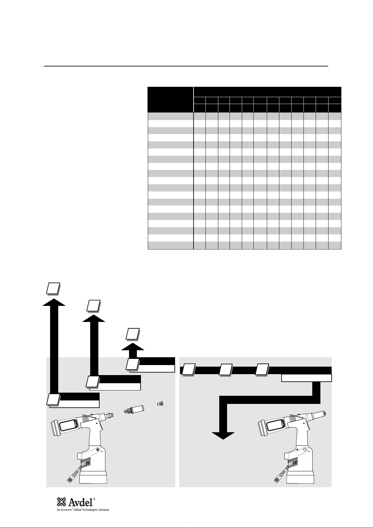
A complete tool is made up of three separate
elements which will be supplied individually.
See diagram below.
NOSE EQUIPMENT MUST BE FITTED AS
DESCRIBED ON PAGES 8-11.
FASTENER
NAME
MM
IN
FASTENER SIZE ( )
AVEX®
STAVEX®
AVINOX®
AVIBULB®
BULBEX®
T-LOK®
AVDEL®SR
INTERLOCK®
HEMLOK®
TLR®
MAXLOK®
AVTAINER®
AVDEL®
MBC
MBC/LC
AVSEAL®
QTM RIVET
TTM RIVET
CHERRYMATETM
4.3 4.8 5 5.2 6 6.4 6.5 7 8 9 9.5 10
–3/16 –––1/4– – – – 3/8–
● ●
● ●
●
● ●
●
● ●
● ●
● ●
●
● ●
● ●
●
●
●
●
● ● ●
● ●
● ●
● ●
COMPLETE TOOL
71231-00 . . . *
BASE TOOL
1
1
2
3
1
NOSE ASSEMBLY
NOSE TIP
2
71231-02000
71210-15000
see note 3
2
3+ + =
3
4
4
The part number of the base tool remains the same whichever nose assembly, or nose tip is fitted. See the General Assembly
pages 18-19. If a Maxlok®nose assembly is fitted, the same base tool MUST be adapted. See details page 11.
The nose tip part number relates to a specific fastener. If access to the application is
restricted, some extended nose tips are available. See ‘type 2 nose tip’ table page 9.
This single nose assembly will allow placing of non-aerospace fasteners by simply selecting the appropriate nose
tip from the range of type 1 nose tips. Other nose assemblies are available for applications with restricted
access, for aerospace and special fasteners. See tables pages 8-10.
* ADD 3 DIGITS FROM THE
LAST COLUMN OF A NOSE TIP
TABLE ON PAGE 8, 9 OR 10.
FOR MAXLOK®, USE MAXLOK®
TABLE PAGE 10 EVEN THOUGH
THERE IS NO NOSE TIP.
Intent of Use
7
English
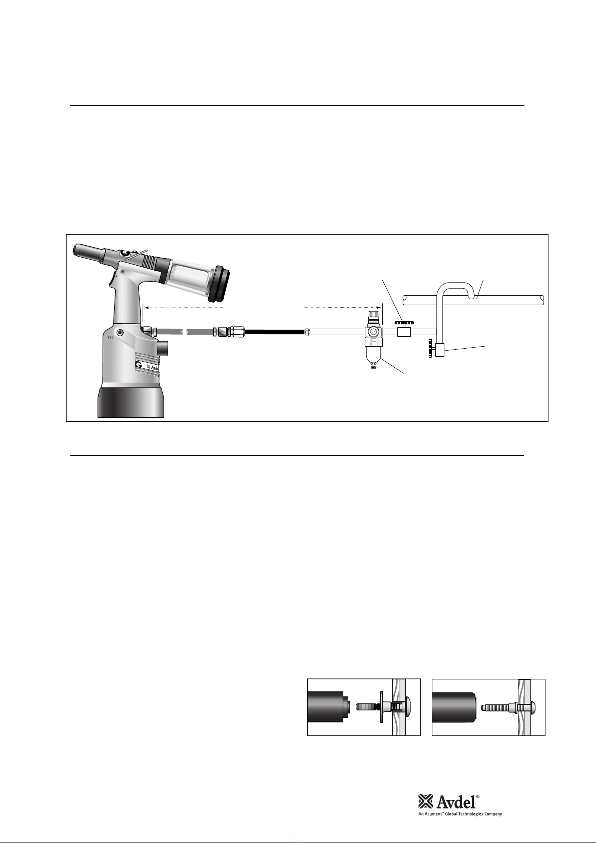
All tools are operated with compressed air at an optimum pressure of 5.5 bar. We recommend the use of pressure regulators and
automatic filtering systems on the main air supply. These should be fitted within 3 metres of the tool (see diagram below) to ensure
maximum tool life and minimum tool maintenance.
Air supply hoses should have a minimum working effective pressure rating of 150% of the maximum pressure produced in the system or
10 bar, whichever is the highest. Air hoses should be oil resistant, have an abrasion resistant exterior and should be armoured where
operating conditions may result in hoses being damaged. All air hoses MUST have a minimum bore diameter of 6.4 millimetres or 1/4
inch.
Read daily servicing details pages 13.
ADJUSTING THE VACUUM EXTRACTION
•Using a screwdriver, turn rotary valve 65 until the air flow at
the rear of the tool ceases.
•With the nose of the tool pointing downwards, insert a
fastener other than Avtainer®or Maxlok®, into the nose and
hold it into position.
•Turn the rotary valve either way until there is sufficient suction
to retain the fastener.
8
6
4
2
0
10
12
14
16
TAKE OFF POINT
FROM
MAIN SUPPLY
STOP COCK
(USED DURING MAINTENANCE
OF FILTER/REGULATOR OR LUBRICATION UNITS)
MAIN SUPPLY
DRAIN POINT
PRESSURE REGULATOR
AND FILTER (DRAIN DAILY)
3 METRES MAXIMUM
4
ALL FASTENERS EXCEPT AVTAINER®AND MAXLOK®
•Ensure that a nose assembly suitable for the fastener is fitted
(see pages 8-10).
•Connect the tool to the air supply.
•Insert the fastener stem into the nose of the tool. The fastener
should remain held in by the vacuum system. If not, adjust the
vacuum extraction rotary valve 65 (see note below).
•Bring the tool with the fastener to the application so that the
protruding fastener enters squarely the hole of the application.
•Fully actuate the trigger. The tool cycle will broach the fastener
and the broken stem will be projected to the rear of the tool.
AVTAINER®AND MAXLOK®
•Ensure that the correct nose assembly is fitted.
•Connect the tool to the air supply.
•Disable the vacuum extraction system by turning rotary
valve 65 until you feel or hear no air flow out of the front of
the nose assembly.
•Push the Maxlok®or Avtainer®stem through the application
hole.
•Place the collar on the stem (orientation as shown below).
•Keeping the head of the stem against the application, push
the tool onto the protruding stem.
•Fully depress the trigger. One cycle will ensure that the
collar is swaged into the lock grooves of the stem and that
the stem breaks at the breaker groove.
•Release the trigger. The tool completes its cycle by pushing
itself off the collar and the spent stem will be pushed to the
rear of the tool on insertion of the next fastener.
Item numbers in bold refer to the general assembly drawing and parts list on pages 18-19.
Placing AVTAINER®Placing MAXLOK®
Putting into Service
Air Supply
Operating Procedure

8
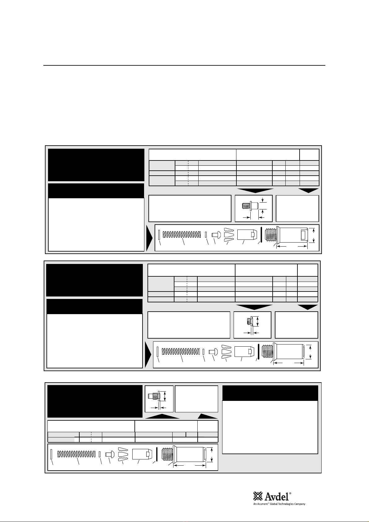
I M P O R T A N T
Nose assemblies do NOT include nose tips. Nose tips must be ordered separately.
A tool must always be fitted with the correct nose assembly and nose tip for your fastener and must be ordered separately, refer to
the ‘NOSE TIPS’ tables below and pages 9-10.
If your application presents no access restriction use a type 1 nose tip unless you are placing aerospace fasteners which require a
type 3 nose tip, Avtainer®a type 5, Hemlok®and 1/4” Interlock®a type 6. Maxlok®requires a special nose assembly which does not
make use of any nose tip, see pages 10-11.
Dimensions ‘A’ and ‘B’ will help you assess the suitability of a particular nose tip.
You should also check that the dimensions of the nose casing will not restrict access to your application. If access is restricted type 2
nose tips with extra reach, are available for some fasteners. Refer to the table on page 9.
It is essential that a fastener-compatible nose assembly and nose tip are fitted prior to operating the tool (no nose tip with Maxlok®).
I M P O R T A N T
The air supply must be disconnected when fitting or removing nose assemblies.
See page 9, except for Avtainer®and Maxlok®see page 11.
1
In inches then in millimetres.
2
Head forming nose tips for use with countersunk heads
ONLY.
3
Long nose tip for deep placing.
4
Material of the body then of the stem. 'Al' is the
abbreviation for Aluminium.
T Y P E 1
N O S E T I P S
F A S T E N E R
MATERIAL
Ø1N O S E T I P ( m m ) see
below
PART Nº 'A' 'B'NAME
Aluminium
Aluminium
Steel
Aluminium
Aluminium
Steel
Steel
Stainless Steel
Steel
Steel
Aluminium
Aluminium
Aluminium
Aluminium
Aluminium
Aluminium
Aluminium
Aluminium
Aluminium
Stainless Steel
Steel
Steel
Steel
Steel
Any
Any
Any
Any
Any
Any
Any
Any
Al/Al4
Al/Al4
Al/Steel4
Al/Steel4
Al/Al4
Al/Al4
Al/Steel4
Al/Steel4
3/16
3/16
3/16
3/16
1/4
3/16
3/16
3/16
3/16
1/4
3/16
–
–
–
–
–
–
3/16
1/4
3/16
–
3/16
3/16
–
3/16
1/4
3/16
3/16
3/16
1/4
3/16
1/4
3/16
3/16
3/16
3/16
1/4
1/4
1/4
1/4
2.8
3.3
3.3
4.1
3.3
3.3
2.8
2.8
2.8
2.8
2.8
5.5
7.3
5.6
7.3
5.6
7.3
4.1
4.4
4.8
3.3
3.3
4.8
3.3
5.7
3.3
5.7
2.8
3.3
3.3
3.3
3.3
9.5
8.0
9.5
9.0
11.2
8.0
10.2
8.3
12.7
19.0
12.7
12.7
12.7
19.0
12.7
12.7
12.7
12.7
12.7
12.7
12.7
12.7
12.7
12.7
12.7
12.7
12.7
12.7
12.7
12.7
12.7
12.7
12.7
12.7
12.7
12.7
12.7
12.7
12.7
12.7
15.9
12.7
15.9
12.7
17.5
12.7
16.7
12.7
07381-04701
07340-04800
07490-04401
07340-066012
07612-02001
07381-04701
07381-04701
07381-04701
07340-04800
07612-02001
07381-04701
71220-16006
71220-160113
71220-16007
71220-160123
71220-16008
71220-160133
07605-00220
71220-16080
07498-01401
07340-06201
07340-06201
07498-01401
07612-02001
07348-07001
71220-60001
71210-16050
07381-04701
07340-06201
07612-02001
07340-06201
07612-02001
703-A-25-6TA
703-B-21
703-A-25-6T
703-B-26
743-A-25-8TA
743-B-21
743-A-25-8T
743-B-26
4.8
4.8
4.8
4.8
6.4
4.8
4.8
4.8
4.8
6.4
4.8
8
8
9
9
10
10
4.8
6.4
4.8
4.3
4.8
4.8
6
4.8
6.4
4.8
4.8
4.8
6.4
4.8
6.4
4.8
4.8
4.8
4.8
6.4
6.4
6.4
6.4
AVEX®
Large flange
STAVEX®
Countersunk
Large flange
BULBEX®
AVSEAL®
TLR®
AVINOX®II
T-LOK®
AVIBULB®
AVDEL®SR
Countersunk
INTERLOCK®
Q
™
RIVET
CHERRYMATE®
T
™
RIVET
Large flange
Large flange
Large flange
Large flange
… 0 1 0
… 0 1 6
… 0 1 7
… 0 1 5
… 0 2 1
… 0 1 6
… 0 1 0
… 0 1 0
… 0 1 0
… 0 2 1
… 0 1 0
… 1 6 5
… 1 8 5
… 1 6 6
… 1 8 6
… 1 6 7
… 1 8 7
… 1 4 0
… 1 4 1
… 0 8 2
… 1 2 0
… 1 2 0
… 0 8 2
… 0 2 1
… 0 6 2
… 0 6 3
… 0 6 4
… 0 1 0
… 1 2 0
… 0 2 1
… 1 2 0
… 0 2 1
… 3 8 0
… 3 8 1
… 3 8 3
… 3 8 4
… 3 8 5
… 3 8 6
… 3 8 7
… 3 8 8
A
B
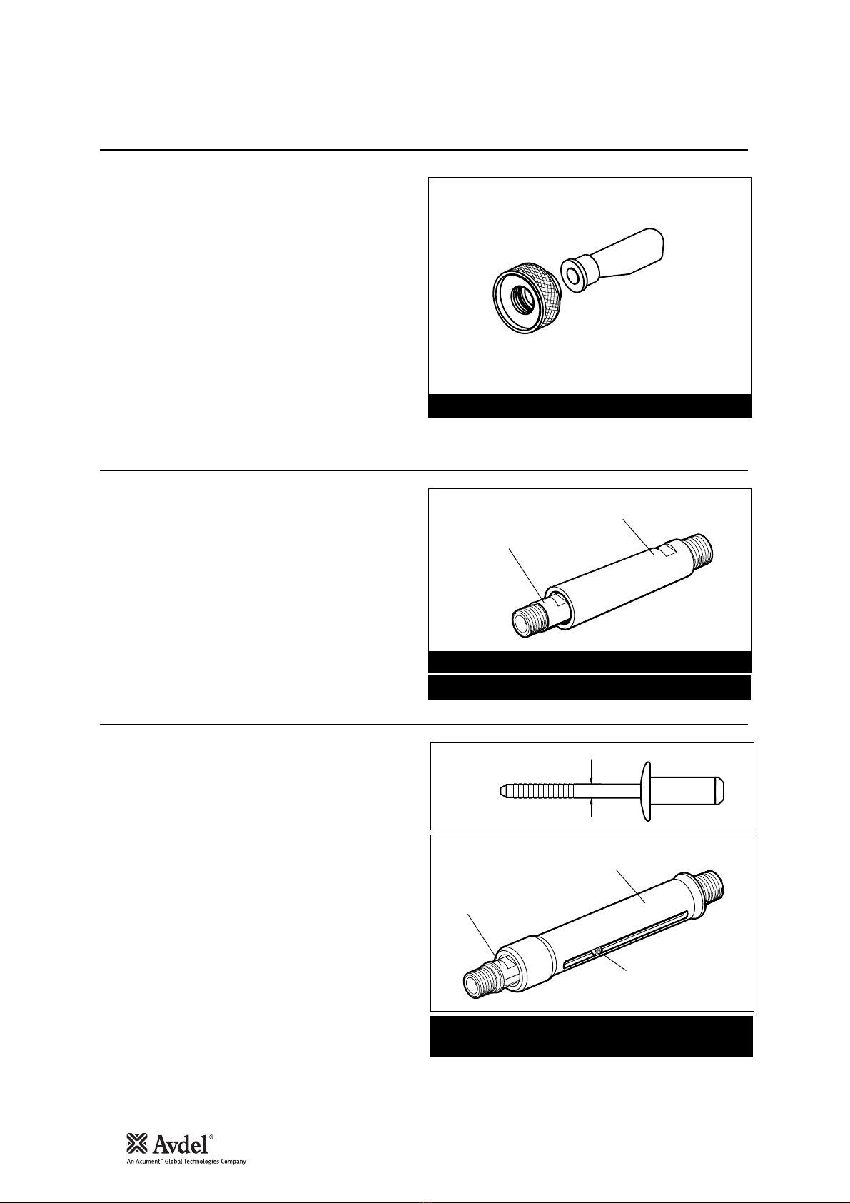
ITEM DESCRIPTION PART Nº
1 NOSE CASING 07340-00306
2 'O' RING 07003-00067
3 JAW HOUSING 07340-00304
4 JAWS 71210-15001
5 JAW SPREADER 07498-04502
6 BUFFER 71210-05001
7 SPRING 07500-00418
8 LOCKING RING 07340-00327
COMPLETE TOOL
PART NUMBER :
precede with
71231-00
8 7 6 5 4 23 1 61
22.9
N O S E A S S E M B L Y
part nº 71210-15000
Fitting Instructions
Nose Assemblies
9
English
Item numbers in bold refer to nose assembly components in type 1,2, 3 and 6 nose tip tables.
•Lightly coat jaws 4with Moly lithium grease*.
•Drop jaws 4into jaw housing 3.
•Insert jaw spreader 5into jaw housing 3.
•Locate buffer 6on jaw spreader 5.
•Locate spring 7onto jaw spreader 5.
•Fit locking ring 8onto the jaw spreader housing.
•Holding tool pointing down, screw the assembled jaw housing onto the jaw spreader housing and tighten with spanner*.
•Screw the nose tip into nose casing 1and tighten with spanner*.
•Place nose casing 1with ‘O’ ring 2over jaw housing 3and screw onto the tool, tightening with spanner*.
* Item included in the G4 service kit. For complete list see page 15.
1
In inches then in millimetres.
F A S T E N E R
MATERIAL
Ø1N O S E T I P ( m m ) see
below
PART Nº 'A' 'B'NAME
Aluminium
Steel
Aluminium
Steel
Steel
3/16
3/16
3/16
–
3/16
10.0
11.8
10.0
10.0
10.0
12.7
12.7
12.7
12.7
12.7
07340-02807
07340-07301
07340-02807
07241-07101
07241-07101
4.8
4.8
4.8
4.3
4.8
AVEX®
BULBEX®
T-LOK®
… 0 1 4
… 0 1 8
… 0 1 4
… 1 2 1
… 1 2 1
ITEM DESCRIPTION PART Nº
1 NOSE CASING 07340-02804
2 'O' RING 07003-00067
3 JAW HOUSING 07340-00304
4 JAWS 71210-15001
5 JAW SPREADER 07498-04502
6 BUFFER 71210-05001
7 SPRING 07500-00418
8 LOCKING RING 07340-00327
COMPLETE TOOL
PART NUMBER :
precede with
71231-00
NOSE ASSEMBLY
part nº 71210-15200
A
B
TYPE 2 NOSE TIPS ARE EXTENDED
TO ALLOW ACCESS INTO
APPLICATIONS WHERE TYPE 1
NOSE TIPS WILL NOT REACH.
T Y P E 2
N O S E T I P S
8 7 6 5 4 23 158.3
22.9
T Y P E 3
N O S E T I P S
COMPLETE TOOL
PART NUMBER :
precede with
71231-00
156.3
22.9
1
In inches then in millimetres.
O
Oversize
N O S E A S S E M B L Y
part nº 71210-15300
ITEM DESCRIPTION PART Nº
1 NOSE CASING 07344-02001
2 'O' RING 07003-00067
3 JAW HOUSING 07340-00304
4 JAWS 71210-15001
5 JAW SPREADER 07498-04502
6 BUFFER 71210-05001
7 SPRING 07500-00418
8 LOCKING RING 07340-00327
F A S T E N E R
MATERIAL
Ø1
N O S E T I P ( m m ) see
below
PART Nº 'A' 'B'NAME
Aluminium
Aluminium
O
Stainless Steel
Any
Any
3/16
3/16
3/16
3/16
3/16
2.5
2.5
2.4
5.1
4.6
12.7
12.7
12.7
12.7
12.7
71210-16036
71210-16037
71220-16038
07340-06901
07344-04701
4.8
4.8
4.8
4.8
4.8
AVDEL®
MBC
MBC L/C
… 2 9 3
… 2 9 4
… 2 9 5
… 3 1 0
… 3 2 0
A
B
8 7 6 5 4 23
TYPE 3 NOSE TIPS ARE SPECIFICALLY
FOR THE AEROSPACE FASTENERS
LISTED ABOVE.
1
In inches then in millimetres.
T Y P E 6
N O S E T I P S
FASTENER MATERIAL
Ø1N O S E T I P ( m m ) see
above
PART Nº 'A' 'B'NAME
Any
Any
1/4
1/4
3.6
3.6
14.3
14.3
07612-02001
07612-02001
6.4
6.4
HEMLOK®
INTERLOCK®… 2 6 1
… 2 6 1
A
B
ITEM DESCRIPTION PART Nº
1 NOSE CASING 07340-00306
2 'O' RING 07003-00067
3 JAW HOUSING 07612-02003
4 JAWS 07612-02002
5 JAW SPREADER 07498-04502
6 BUFFER 07498-03003
7 SPRING 07500-00418
8 LOCKING RING 07340-00327
COMPLETE TOOL
PART NUMBER :
precede with
71231-00
8 7 6 5 4 3 1 61
22.9
N O S E A S S E M B L Y
part nº 71230-15800
2
Nose Assemblies

10
Nose Assemblies
T Y P E 5
N O S E T I P
COMPLETE TOOL
PART NUMBER :
precede with
71231-00
1
1
In inches then in millimetres
N O S E A S S E M B L Y part nº 71230-15600
ITEM DESCRIPTION PART Nº
1 NOSE CASING 07498-00501
2 'O' RING 07003-00067
9 CHUCK COLLET 07498-00801
4 JAWS 07220-02302
ITEM DESCRIPTION PART Nº
10 FRONT SPRING GUIDE 07498-00803
7 SPRING 07500-02005
11 REAR SPRING GUIDE 07498-00503
8 LOCKING RING 07340-00327
F A S T E N E R
MATERIAL
Ø1
N O S E T I P ( m m ) see
below
PART Nº 'A' 'B'NAME
Steel
3/8
4.119.107498-00802
9.6
… 2 4 3
98.5
20.6
11 7 10 4 298
A
B
AVTAINER®
M A X L O K ®-
N O N O S E T I P
12
1
In inches then in millimetres
NOSE ASSEMBLY NOSE ASSEMBLY
part nº 07610-02000 for
3
/
16
" ø part nº 07610-02100 for
1
/
4
" ø
ITEM DESCRIPTION PART Nº
9
CHUCK COLLET 07610-02002
4 JAWS 07610-02003
10 SPRING GUIDE 07220-02104
7 SPRING 07610-02107
8 LOCKING RING 07610-02004
12 ANVIL
07610-02001
ITEM DESCRIPTION PART Nº
9
CHUCK COLLET 07610-02102
4 JAWS 07610-02103
10 SPRING GUIDE 07220-02104
7 SPRING 07610-02107
8 LOCKING RING 07610-02004
12 ANVIL
07610-02101
THE THREE COMPONENTS ILLUSTRATED LEFT ARE ESSENTIAL WHEN FITTING
A MAXLOK®NOSE ASSEMBLY TO THE G4 TOOL.
READ MAXLOK®'FITTING INSTRUCTIONS' PAGE 11.
F A S T E N E R
MATERIAL
Ø1
N O S E A S S E M B L Y see
below
PART NºNAME
All
All
3/16
1/4
07610-02000
07610-02100
4.8
6.4
MAXLOK®… 3 7 1
… 3 7 2
8 7 10 9410
64.5
19
COMPLETE TOOL PART NUMBER :
precede with 71231-00
The three adapting components
illustrated below left are
not included in the nose
assembly part number.
Each item must be ordered
separately, using individual
part numbers.
MAXLOK®NOSE ASSEMBLIES
will place both the ordinary flange
collar and the large flange collars.
07610-00501
CHUCK COLLET ADAPTOR
CHUCK COLLET ADAPTOR
71230-02063
ANVIL ADAPTOR
ANVIL ADAPTOR
07610-00307
ANVIL NUT
ANVIL NUT

11
English
I M P O R T A N T
The air supply must be disconnected when fitting or removing any nose assembly unless specifically instructed
otherwise.
The air vacuum extraction system MUST be disabled before operating a G4 tool with a Maxlok®or Avtainer®nose
assembly.
Refer to the ‘Operating Procedure’ for Avtainer®and Maxlok®, page 7.
AVTAINER®
Item numbers in bold refer to the general assembly and parts
list pages 18-19. Other items numbers refer to the‘type 5 nose
tip’ table page 10.
•Remove jaw spreader housing 1, ‘O’ ring 2, and vacuum
tube 51.
•Replace jaw spreader housing 1, ‘O’ ring 2.
•Lightly coat jaws 4with Moly Lithium grease*.
•Drop jaws 4into chuck collet 9.
•Insert front spring guide 10 into chuck collet 9.
•Locate spring 7onto front spring guide 10.
•Screw rear spring guide 11 into chuck collet 9.
•Fit locking ring 8onto the jaw spreader housing of the tool.
•Screw the assembled chuck collet onto the jaw spreader
housing and tighten with spanner.
•Screw the nose tip into nose casing 1 and tighten with
spanner*.
•Place nose casing 1with ‘O’ ring 2over chuck collet 9and
screw onto the tool, tightening with spanner*
MAXLOK®
When fitting a Maxlok®nose assembly, the base tool must be
adapted using three auxiliary components illustrated page 10.
Item numbers in bold refer to the general assembly and parts
list pages 18-19. Other items numbers refer to the ‘Maxlok®no
nose tip’ table page 10.
•Remove jaw spreader housing 1, ‘O’ ring 2, and vacuum
tube 51.
•Substitute jaw spreader housing 1with chuck collet adaptor
07610-00501. Tighten fully onto piston before tightening
the locknut against it.
•Fit locking ring 8onto the chuck collet adaptor.
•Lightly coat jaws 4with Moly lithium grease.
•Drop jaws 4into or chuck collet 9.
•Insert one spring guide 10 into chuck collet 9.
•Locate spring 7onto the spring guide already in place.
•Drop the other spring guide 10 into spring 7.
•Holding tool pointing down, screw the assembled chuck
collet onto the chuck collet adaptor and tighten with
spanner.
•Screw anvil adaptor 71230-02063 into the head assembly.
•Place anvil 12 over chuck collet 9and lock into place with
anvil nut 07610-00307.
Nose assemblies should be serviced at weekly intervals. You should hold some stock of all internal components of the nose
assembly and nose tips as they will need regular replacement.
•Remove the nose assembly using the reverse procedure to the ‘Fitting instructions’.
•Any worn or damaged part should be replaced.
•Clean and check wear on jaws.
•Ensure that the jaw spreader is not distorted.
•Check that the spring is not distorted.
•On nose assemblies for Maxlok®and Avtainer®check that the spring guides are not distorted.
•On nose assemblies for Maxlok®check that the anvil is neither cracked nor has any scoring or corrosion marks on the inside face
of the concave shape at the front end.
•Assemble according to fitting instructions.
* Item included in the G4 service kit. For complete list see page 15.
Nose Assemblies
Fitting instruction for Maxlok®and Avtainer®Nose Assemblies
Servicing instructions for all Nose Assemblies
12
Accessories
Stem Deflector
Extension
Side Ejector
ADAPTOR NUT
71210-20101
STEM DEFLECTOR
07340-00342
The stem deflector is a very simple alternative to the standard
stem collector and allows access in restricted areas. It is easy
to fit to the tool as follows:
•Unscrew retaining nut 26 by inserting a 3 millimetre
diameter rod into one of the holes.
•Remove retaining nut 26 and the stem collector assembly,
items 18, 20, 21, 22, 23, 24, and 25.
•Screw the adaptor nut onto end cap 27.
•Push the boss end of the stem deflector into the internal
groove of the adaptor nut.
•Rotate the stem deflector until the aperture faces away
from the operator and other person(s) in the vicinity.
Item numbers in bold refer to the general assembly drawing and parts list on pages 18-19.
INNER
EXTENSION
OUTER CASING
KIT PART NUMBER: 71210-20100
STANDARD EXTENSION PART NUMBER: 71210-20300
INNER
EXTENSION
OUTER CASING
8-32 x 1/4" SOCKET
CAP HEAD SCREW
Part number: 07498-00900
for fasteners with a stem larger than 3.1 mm (1/8") Ø
STEM DIAMETER
Fitted between the tool and the nose assembly, the extension
gives an extra reach of 76 millimetres, ideal for use in deep
narrow applications.
•To fit the extension, remove any nose assembly
components.
•Screw the inner extension onto jaw spreader housing 1.
•Screw the outer casing onto head assembly 4.
•Screw the nose assembly onto the extension.
Fitted between the tool and the nose assembly, the side
ejector forces fastener stems to eject at the front of the tool
and gives an extra reach of 90mm. It is not an option when
placing Maxlok®fasteners.
•To fit the side ejector, remove any nose assembly
components.
•Remove the socket cap screw from the side ejector.
•Screw the inner extension onto jaw spreader housing 1.
•Screw the outer casing onto head assembly 4.
•Replace the socket cap screw securing with Loctite
Screwlock 222, part number 07900-00371.
•Screw the nose assembly onto the side ejector.
For greater ease of use, it is recommended that the stem
collector or stem deflector is replaced with safety cap part
number 71210-20201. ‘O’ ring 19 must remain.
3/16" & 1/4" MAXLOK®EXTENSION: 71230-20300

13
English
•Daily, before use or when first putting the tool into service, pour a few drops of clean, light lubricating oil into the air inlet of the
tool if no lubricator is fitted on air supply. If the tool is in continuous use, the air hose should be disconnected from the main air
supply and the tool lubricated every two to three hours.
•Check for air leaks. If damaged, hoses and couplings should be replaced.
•If there is no filter on the pressure regulator, bleed the air line to clear it of accumulated dirt or water before connecting the air
hose to the tool. If there is a filter, drain it.
•Check that the nose assembly is correct for the fastener to be placed.
•Check that the stroke of the tool meets the minimum specification (page 5). The last step of the Priming Procedure on page 19
explains how to measure the stroke.
•Either a stem collector or a stem deflector must be fitted to the tool if the vacuum extraction is ‘ON’. If it is turned ‘OFF’ a safety
cap must be fitted. See ‘side ejector’ opposite.
•Check that base cover 40 is fully tightened onto body 38.
•Ensure that rotary valve 65 is correctly adjusted for fastener retention or turned off for Avtainer®and Maxlok®(see ‘Operating
Procedure’ page 7).
•Dismantle and clean nose assembly, with special attention to the jaws. Lubricate with Moly Lithium grease EP 3753 before
assembling.
•Check for air leaks.
Grease can be ordered as a single item, the part number is shown in the service kit page 15.
First Aid
SKIN:
As the grease is completely water resistant it is best removed with an approved emulsifying skin cleaner.
INGESTION:
Ensure the individual drinks 30ml Milk of Magnesia, preferably in a cup of milk.
EYES:
Irritant but not harmful. Irrigate with water and seek medical attention.
Fire
FLASH POINT: Above 220°C.
Not classified as flammable.
Suitable extinguishing media: CO2, Halon or water spray if applied by an experienced operator.
Environment
Scrape up for burning or disposal on approved site.
Handling
Use barrier cream or oil resistant gloves
Storage
Away from heat and oxidising agent.
Item numbers in bold refer to the general assembly drawing and parts list on pages 18-19.
I M P O R T A N T
Read Safety Instructions on page 4.
The employer is responsible for ensuring that tool maintenance instructions are given to the appropriate personnel.
The operator should not be involved in maintenance or repair of the tool unless properly trained.
The tool shall be examined regularly for damage and malfunction.
Servicing the Tool
Daily
Weekly
Moly Lithium Grease EP 3753 Safety Data

14
Specifications
MolyKote 55m Grease Safety Data
MolyKote 111 Grease Safety Data
First Aid
SKIN:
Flush with water. Wipe off.
INGESTION:
No first aid should be needed.
EYES:
Flush with water.
Fire
FLASH POINT: Above 101.1°C. (closed cup)
Explosive Properties: No
Suitable Extinguishing Media: Carbon Dioxide Foam, Dry Powder or fine water spray.
Water can be used to cool fire exposed containers.
Environment
Do not allow large quantities to enter drains or surface waters.
Methods for cleaning up: Scrape up and place in suitable container fitted with a lid. The spilled product produces an extremely
slippery surface.
Harmful to aquatic organisms and may cause long-term adverse effects in the aquatic environment. However, due to the physical
form and water - insolubility of the product the bioavailability is negligible.
Handling
General ventilation is recommended. Avoid skin and eye contact.
Storage
Do not store with oxidizing agents. Keep container closed and store away from water or moisture.
First Aid
SKIN:
No first aid should be needed.
INGESTION:
No first aid should be needed.
EYES:
No first aid should be needed.
INHALATION:
No first aid should be needed.
Fire
FLASH POINT: Above 101.1°C. (closed cup)
Explosive Properties: No
Suitable Extinguishing Media: Carbon Dioxide Foam, Dry Powder or fine water spray.
Water can be used to cool fire exposed containers.
Environment
No adverse effects are predicted.
Handling
General ventilation is recommended. Avoid eye contact.
Storage
Do not store with oxidizing agents. Keep container closed and store away from water or moisture.

15
English
The airline must be disconnected before any servicing or dismantling is attempted unless specifically instructed otherwise.
It is recommended that any dismantling operation be carried out in clean conditions.
Before proceeding with dismantling, empty the oil from the tool following the first three steps of the 'Priming Procedure' on page 21.
Prior to dismantling the tool it is necessary to remove the nose equipment. For instructions see the nose equipment section, pages 8-
11.
For a complete service of the tool, we advise that you proceed with dismantling of sub-assemblies in the order shown.
After any dismantling REMEMBER to prime the tool and to fit an appropriate nose assembly or swivel head.
I M P O R T A N T
Read Safety Instructions on page 4.
The employer is responsible for ensuring that tool maintenance instructions are given to the appropriate
personnel.
The operator should not be involved in maintenance or repair of the tool unless properly trained.
The tool should be examined regularly for damage and malfunction.
* Item included in the G4 service kit.
Item numbers in bold refer to the general assembly drawing and parts list on pages 18-19.
•Unscrew retaining nut 26 and pull off stem collector assembly, items 15, (72) 18, 20, 21, 22, 23, 24, 25 and ‘O’ ring 19.
•Using the ‘T’ spanner*, remove end cap 27 (73) together with seal 17 ‘O’ ring 16 and lip seal 28 and spring 70.
•Loosen locknut 3with a spanner* then unscrew jaw spreader housing 1and ‘O’ ring 2.
•Remove locknut 3together with ‘O’ rings 49 and 50.
•Push head piston 7to the rear and out of head assembly 4taking care not to damage the cylinder bore.
•Remove seal retainer 30. Push lip seal 8to the rear and out of head assembly 4taking care again not to damage the cylinder
bore.
•Remove seal housing 5and lip seal 67.
PART Nº DESCRIPTIONPART Nº DESCRIPTION
SERVICE KIT : 71210-99990 Spanners are specified in inches and across flats unless otherwise stated
07900-00667 PISTON SLEEVE
07900-00692 TRIGGER VALVE EXTRACTOR
07900-00670 BULLET
07900-00672 'T' SPANNER
07900-00706 'T' SPANNER SPIGOT
07900-00684 GUIDE TUBE
07900-00685 INSERTION ROD
07900-00351 3 MM ALLEN KEY
07900-00469 2.5 MM ALLEN KEY
07900-00158 2 MM PIN PUNCH
07900-00164 CIRCLIP PLIERS
07900-00008 7/16 x 1/2SPANNER
07900-00012 9/16 x 5/8SPANNER
07900-00015 5/8x 11/16 SPANNER
07900-00686 PEG SPANNER
07900-00677 SEAL EXTRACTOR
07900-00698 STOP NUT
07900-00700 PRIMING PUMP
07992-00020 GREASE - MOLY LITHIUM E.P.3753
07992-00075 GREASE - MOLYKOTE 55M
07900-00755 GREASE - MOLYKOTE 111
(or every 500,000 cycles whichever is the soonest)
Annually or every 500,000 cycles the tool should be completely dismantled and new components should be used where worn,
damaged or recommended. All ‘O’ rings and seals should be renewed and lubricated with MolyKote 55m grease for pneumatic sealing
or MolyKote 111 for hydraulic sealing.
For an easy complete service, Avdel is offering a complete service kit.
Servicing the Tool
Annually
Head Assembly

16
Assemble in reverse order to dismantling noting the following points:
•Place lip seal 8onto the insertion rod* ensuring correct orientation. Push the guide tube* into the head of the tool and push the
insertion rod* with the seal into place through the guide tube*. Pull the insertion rod* out then the guide tube.
•Drop seal retainer 30 against lip seal 8large flange first.
•Fit seals 11 and 13 onto the piston.
•Lubricate the cylinder bore and place the piston sleeve* into the back of head assembly 4. Slide the bullet* onto the threaded part
of piston 7and push the piston with the seals through the piston sleeve* as far as it will go. Slide the bullet* off the piston and
remove the piston sleeve.
•Fit seal housing 5and lip seal 67.
•Tighten jaw spreader housing 1fully tightened onto head piston 7BEFORE tightening locknut 3against it.
•Use Loctite 932 when reassembling Retaining Nut 26.
•Remove ‘ON/OFF’ valve assembly 60.
•Clamp the body of the inverted tool ACROSS THE AIR INLET BOSSES in a vice fitted with soft jaws.
•Pull off rubber boot 80.
•Using the peg spanner* unscrew base cover 40.
•Unscrew locknuts 76 (2 off) and remove base plate 77.
•Remove liner 45 together with sealing washers 75 (2 off) and 'O' rings 78 (2 off).
•Remove pneumatic piston assembly 42 together with ‘O’ ring 39, lip seal 41 (3 off) and guide ring 35.
Assemble in reverse order.
•Remove pneumatic piston assembly 42 and seal assembly 34 as described immediately above.
•Using the ‘T’ spanner* and ‘T’ spanner spigot* undo clamp nut 36 and remove it together with clamp plate 63, transfer tube
assembly 44, ‘O’ ring 6, valve rod 43 and silencer pads 62.
•Release the tool from the vice and separate body 38 with ‘O’ ring 31 from handle assembly 32.
•Remove ‘O’ ring 33 from the intensifier tube and pull off head assembly 4from handle assembly 32.
•Push out valve seat 64 with both ‘O’ rings 6.
•Pull out all the components of valve spool assembly 54.
•Finally remove ‘O’ ring 59 out of the handle counterbore.
Assemble in reverse order noting the following points -
•Ensure that the central port in valve seat 64 faces upwards.
•Use Loctite 243 when reassembling Clamp Nut 36, torque to 11ft lb (14.91 Nm).
•Using the 2 millimetre diameter pin punch*, drive trigger pin 48 out and lift off trigger 47.
•Unscrew trigger valve 46 using the trigger valve extractor*.
Assemble in reverse order to dismantling.
I M P O R T A N T
Check the tool against daily and weekly servicing
Priming is ALWAYS necessary after the too has been dismantled and prior to operating.
* Item included in the G4 service kit. For complete list see page 15.
Item numbers in bold refer to the general assembly drawing and parts list on pages 18-19.
Servicing the Tool
Head Assembly
Pneumatic Piston Assembly
Valve Spool Assembly
Trigger

17
EnglishNotes
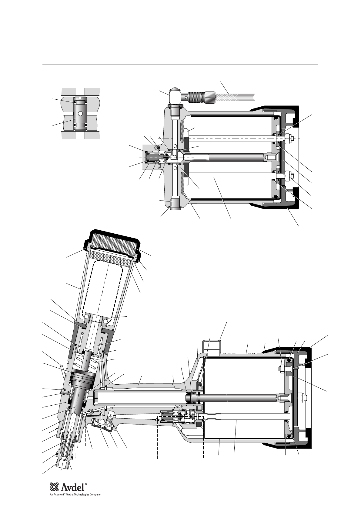
18
General Assembly of Base Tool 71231-02000
B - B
6665
37
84
85
86
87
38
40
39
83
31
33
34
A
A
44
45
36
35
B
B
1 2 3 4 9 105 8
31
30
32
46
48
67
47
51 50 49
26
73
70 28
72 16
17 18
14
20 21
22
25 24
11
7
A23
13
88
42
41
80
8281
A - A
6
64
5958
57
54-56
55
52 53 6
61
60
69
6
74
80
41 76 7577 78
62 63

19
English
01
02
03
04
05
06
07
08
09
10
11
13
14
16
17
18
20
21
22
23
24
25
26
28
30
31
32
33
34
35
36
37
38
39
40
41
42
44
45
46
71210-02101
07003-00277
71230-02015
71230-03300
71210-02104
07003-00281
71231-02003
07003-00273
71230-02041
07003-00194
07003-00341
07003-00342
71210-02022
07003-00278
71210-02029
07003-00311
07640-00239
71210-02051
07640-00244
71210-02034
07340-00335
71210-02035
71210-02028
07003-00374
71230-02019
07003-00288
71221-02013
07003-00287
71230-03800
71230-03205
71210-02014
71231-02027
71221-02001
07003-00182
71221-02002
07003-00274
71231-03210
71230-03600
71221-02008
07005-00088
JAW SPREADER HOUSING
'O' RING
LOCKNUT
HEAD ASSEMBLY
SEAL HOUSING
'O' RING
HEAD PISTON
LIP SEAL
SCREW
BONDED SEAL
LIP SEAL
'O' RING
SUSPENSION RING
'O' RING
SEAL
'O' RING
STEM COLLECTOR OUTER
STEM COLLECTOR BODY
SILENCER
SILENCER CAP
STEM COLLECTOR END CAP
SILENCER
RETAINING NUT
LIP SEAL
SEAL RETAINER
'O' RING
HANDLE ASSEMBLY
'O' RING
INTENSIFIER SEAL ASSEMBLY
GUIDE RING
CLAMP NUT
LABEL
BODY
'O' RING
BASE COVER
LIP SEAL
PNEUMATIC PISTON ASSEMBLY (INCLUDES 41/35/39)
TRANSFER TUBE ASSEMBLY
CYLINDER LINER
TRIGGER VALVE
1
1
1
1
1
3
1
1
1
1
1
2
1
1
1
1
1
1
1
1
1
1
1
1
1
1
2
1
1
1
1
1
1
1
1
3
1
1
1
1
-
1
1
-
-
3
-
1
1
2
1
2
1
1
1
1
-
-
1
-
-
1
-
-
-
-
2
1
1
-
-
1
-
1
-
1
-
-
-
-
47
48
49
50
51
52
53
54
55
56
57
58
59
60
61
62
63
64
65
66
67
68
69
70
72
73
74
75
76
77
78
79
80
81
82
83
84
85
86
87
88
71210-02008
71210-02024
07003-00310
07003-00204
71230-02102
07003-00127
07005-01274
71210-03400
07003-00268
71210-03402
71210-03401
07003-00042
07003-00271
71210-03700
07008-00010
71210-02031
71221-02003
71210-02009
71210-02013
07003-00189
07003-00333
07900-00707
07007-00224
07490-03002
71403-02110
71231-02001
71221-02004
71221-02006
07002-00108
71221-02005
07003-00027
71221-02003
71221-02007
07007-01993
71221-20104
07002-00098
71221-20105
71221-20101
71221-20102
71221-20103
07007-01503
TRIGGER
TRIGGER PIN
'O' RING
'O' RING
VACUUM SLEEVE
'O' RING
1/8" BSP PLUG
VALVE SPOOL ASSEMBLY (55 to 58)
• 'O' RING
• VALVE SPOOL
• VALVE BODY
• 'O' RING
'O' RING
ON/OFF VALVE ASSEMBLY
6" FLEXIBLE HOSE
SILENCER
TOP PLATE
VALVE SEAT
ROTARY VALVE
'O' RING
LIP SEAL
TOOL INSTRUCTION MANUAL
SPIROL PINS
SPRING
BOTTLE ADAPTOR ASSEMBLY
END CAP ASSEMBLY
TIE ROD
SEALING WASHER
M6 NYLOK NUT
BASE PLATE
'O' RING
TOP PLATE
RUBBER BOOT
CENTRE POLE MAGNET
M5 X 19 COUNTERSUNK SCREW
M5 NYLOK NUT
COUNTER
COUNTER MOULDING
SPECIAL M4 SCREW
MOULD RETAINING NUT
LABEL BOOK SYMBOL
1
1
2
1
1
1
1
1
1
1
1
1
1
1
1
2
1
1
1
2
1
1
2
1
1
1
2
2
2
1
2
1
1
1
1
1
1
1
2
2
1
-
-
2
1
-
1
-
-
2
-
-
2
1
-
-
2
-
1
–
2
-
1
-
-
-
-
-
-
-
-
-
-
-
-
-
-
-
-
-
-
-
ITEM PART Nº DESCRIPTION ITEM PART Nº DESCRIPTION
71231-02000 PARTS LIST *These are minimum recommended levels of spares based on regular servicing
QTY SPARES QTY SPARES
Parts List for 71231-02000

20
Priming
Oil Details
Hyspin VG 32 Oil Safety Data
Priming Kit
To enable you to follow the priming procedure opposite, you will need to obtain a priming kit:
PART Nº DESCRIPTION
PRIMING KIT : 07900-00688
07900-00351 3mm ALLEN KEY
07900-00698 STOP NUT
07900-00700 PRIMING PUMP
07900-00224 4mm ALLEN KEY
07900-00734 MAXLOK®STOP NUT
Priming is ALWAYS necessary after the tool has been dismantled and prior to operating. It may also be necessary to restore the full
stroke after considerable use, when the stroke may be reduced and fasteners are not fully placed by one operation of the trigger.
The recommended oil for priming is Hyspin VG32 available in 0.5l (part number 07992-00002) or one gallon containers (part number
07992-00006). Please see safety data below.
First Aid
SKIN:
Wash thoroughly with soap and water as soon as possible. Casual contact requires no immediate attention. Short term contact requires no
immediate attention.
INGESTION:
Seek medical attention immediately. DO NOT induce vomiting.
EYES:
Irrigate immediately with water for several minutes. Although NOT a primary irritant, minor irritation may occur following contact.
Fire
Flash point 232°C. Not classified as flammable.
Suitable extinguishing media: CO2, dry powder, foam or water fog. DO NOT use water jets.
Environment
WASTE DISPOSAL: Through authorised contractor to a licensed site. May be incinerated. Used product may be sent for reclamation.
SPILLAGE: Prevent entry into drains, sewers and water courses. Soak up with absorbent material.
Handling
Wear eye protection, impervious gloves (e.g. of PVC) and a plastic apron. Use in well ventilated area.
Storage
No special precautions.
Table of contents
Languages:
Other Avdel Nail Gun manuals


