Avdel 07200 User manual

0720 type
07200-07201
Pneumatic Power Tool

3
Contents
Safety Rules 4
Tool Specifications 5
Intent of Use 6
Dimensions 6
Putting into Service
Air Supply 7
Operating Procedure 7
Accessories 8
Collar Splitters 8
Collar Splitter Assembly and Adaptor Kit 9
Nose Assemblies 10
Selection 10
Components 10
Fitting & Servicing Instructions 11
Servicing the Tool
Daily / Weekly 12
Moly Lithium Grease EP 3735 Safety Data 12
Service Kit 13
Maintenance
07200 Offset Adaptor Assembly 07200 Tool 14
Straight Adaptor 07201 Tool 14
Handle Assembly 14
Pneumatic Cylinder 15
Air Throttle Valve 15
Spindle Housing Assembly 15
Re-setting 07200 & 07201 Tools 15
General Assembly of Base Tools
General Assembly and Parts List 16-17
Fault Diagnosis
Symptom, Possible Cause & Remedy 18
Avdel UK Limited policy is one of continuous product development and improvement and we reserve the right to change the specification of any product without prior notice.
Warranty
Avdel UK Limited installation tools carry a 12 month warranty against defects
caused by faulty materials or workmanship, the warranty period commencing from the
date of delivery confirmed by invoice or delivery note.
The warranty applies to the user/purchaser when sold through an authorised outlet,
and only when used for the intended purpose. The warranty is invalidated if the
installation tool is not serviced, maintained and operated according to the instructions
contained in the Instruction and Service Manuals.
In the event of a defect or failure, and at its sole discretion, Avdel UK Limited
undertakes only to repair or replace faulty components.
CONTENTS

4
1Do not use outside the design intent.
2Do not use equipment with this tool/machine other than that recommended and supplied by Avdel UK Limited.
3Any modification undertaken by the customer to the tool/machine, nose assemblies, accessories or any equipment supplied by
Avdel UK Limited or their representatives, shall be the customer’s entire responsibility. Avdel UK Limited will be pleased to
advise upon any proposed modification.
4The tool/machine must be maintained in a safe working condition at all times and examined at regular intervals for damage and function
by trained competent personnel. Any dismantling procedure shall be undertaken only by personnel trained in Avdel UK Limited
procedures. Do not dismantle this tool/machine without prior reference to the maintenance instructions. Please contact Avdel UK Limited
with your training requirements.
5The tool/machine shall at all times be operated in accordance with relevant Health and Safety legislation. In the U.K. the “Health and
Safety at Work etc. Act 1974” applies. Any question regarding the correct operation of the tool/machine and operator safety should be
directed to Avdel UK Limited.
6The precautions to be observed when using this tool/machine must be explained by the customer to all operators.
7Always disconnect the airline from the tool/machine inlet before attempting to adjust, fit or remove a nose assembly.
8Do not operate a tool/machine that is directed towards any person(s) or the operator.
9Always adopt a firm footing or a stable position before operating the tool/machine.
10 Ensure that vent holes do not become blocked or covered and that the hoses are always in good condition.
11 The operating pressure shall not exceed 6.5 bar (95 lbf/in2).
12 Do not operate the tool without full nose equipment in place.
13 Care shall be taken to ensure that spent stems are not allowed to create a hazard.
14 07200 tools must be fitted with an undamaged pintail deflector before operating.
15 Avoid holding the head of the tool during initial connection as it may move and could cause injury.
16 When using the tool, the wearing of safety glasses is required both by the operator and others in the vicinity to protect against pin
ejection, should a fastener be placed ‘in air’. We recommend wearing gloves if there are sharp edges or corners on the application.
17 Take care to avoid entanglement of loose clothes, ties, long hair, cleaning rags etc. in the moving parts of the tool which should be kept
dry and clean for best possible grip.
18 When carrying the tool from place to place keep hands away from the trigger/lever to avoid inadvertent start up.
19 Ensure the plug filling the circlip removal aperture is in place at all times.
This instruction manual must be read with particular attention to the following safety rules, by any person
installing, operating, or servicing this tool.
Safety Rules

5
Specifications
TOOL SPECIFICATION
Air Pressure Minimum - Maximum 5.4-6.5 bar (80-95 lbf/in2)
Free Air Volume Required @ 5.4 bar/80 lbf/in26.2 litres (.22 ft3)
Stroke Minimum 12.7 mm (.5 in)
Pull Force 07200 @ 5.4 bar/80 lbf/in214.68 kN (3300 lbf)
07201 @ 5.4 bar/80 lbf/in218 kN (4050 lbf)
Cycle time Approximately 1.5 seconds
Noise Level 07200 74.4 dB(A)
07201 72.7 dB(A)
Weight Without nose equipment 4.54 kg (10 lb)
Vibration 07200 2.58 m/s2
07201 2.93 m/s2

6
Intent of Use
The pneumatic 0720 type tool is designed to place 3/16” & 1/4” Avdelok®pins and collars at high speed making it ideal for batch or flow-line
assembly in a wide variety of applications throughout all industries.
There are two models offering different access to your application. The base tool part number for the 07200 model is 07200-00200 and
07201-00200 for the 07201 model. Select the one most suited to your application requirements. All nose assemblies are available for both
models (details pages 10-11).
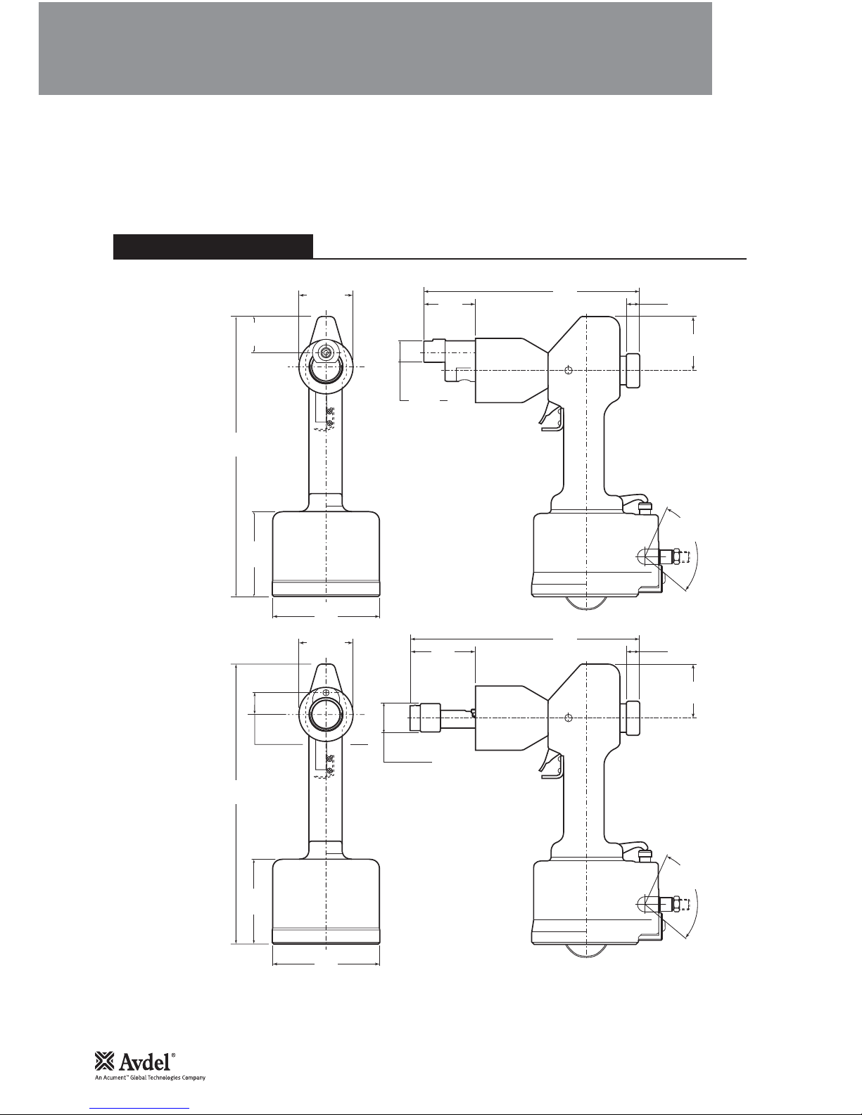
29 Ø
1.15 Ø
17
0.68
60
2.38
105°SWIVEL
(AIR INLET)
13
0.50
96
3.75
323
12.70
63 Ø
2.50 Ø
127
5.00
83.8
3.30
269
10.60
17
0.68
60
2.38
105°SWIVEL
(AIR INLET)
39
1.55
96
3.75
323
12.70
63 Ø
2.50 Ø
29 DIA
1.15 DIA
127
5.00
69
2.70
254
10.00
TOOL DIMENSIONS
07200 MODEL
07201 MODEL
Dimensions shown in bold are millimetres. Other dimensions are in inches.

7
Putting into Service
AIR SUPPLY
All tools are operated with compressed air at an optimum pressure of 5.4 bar. We recommend the use of pressure regulators and automatic
oiling/filtering systems on the main air supply. These should be fitted within 3 metres of the tool (see diagram below) to ensure maximum tool
life and minimum tool maintenance.
Air supply hoses should have a minimum working effective pressure rating of 150% of the maximum pressure produced in the system or 10
bar, whichever is the highest. Air hoses should be oil resistant, have an abrasion resistant exterior and should be armoured where operating
conditions may result in hoses being damaged. All air hoses MUST have a minimum bore diameter of 6.4 millimetres or
1
/4”.
Read daily servicing details pages 12-13.
•Ensure that the correct nose assembly is fitted.
•Connect the tool to the air supply.
•Push the Avdelok
® pin through the application hole .
•Place the collar on the pin (orientation as shown right).
•Keeping the head of the pin against the application, push the tool onto the
protruding pin tail.
•Fully depress the trigger. One cycle will ensure that the collar is swaged
into the lock grooves of the pin and the the pin breaks at the breaker
groove.
•Release the trigger. The tool completes its cycle by pushing itself off the
collar and ejecting the pin tail at the rear.
8
6
4
2
0
01
2
1
41
61
TAKE OFF POINT
FROM MAIN SUPPLY
STOP COCK
(USED DURING MAINTENANCE
OF FILTER/REGULATOR
OR LUBRICATION UNITS)
MAIN SUPPLY
DRAIN POINT
PRESSURE REGULATOR
AND FILTER
(DRAIN DAILY)
LUBRICATOR
3
M
E
T
R
E
S
M
A
X
I
M
U
M
OPERATING PROCEDURE

8
Accessories
Three accessories are available to make the connection to your air supply.
1/4" BSP
TO FIT 6.4 mm (1/4") BORE PIPE
1/4" BSP L = 137 cm
Double Male Connector
part no 07005-00041
Hose Assembly
part no 07008-00324
Hose Connector
part no 07005-00276
ACCESSORIES
You can order collar splitters to cut the collars off placed 3/16” & 1/4” Avdelok®.
COLLAR SPLITTERS - COMPONENT PART NUMBERS
DESCRIPTION QTY
ITEM
Nº
3/16" COLLAR
SPLITTER
07500-06800
1/4" COLLAR
SPLITTER
07500-06900
1
6-32 UNC x 3/8SOCKET CAP SCREW
07001-00004 07001-00004 2
2 SLEEVE 07210-02012 07210-02012 1
3 BLADE PIN 07210-02014 07210-02014 2
4 BLADE PIN SCREW 07210-02015 07210-02015 2
5 BLADE 07210-02016 07210-02104 2
6 SPRING CLIP ASSEMBLY 07500-08000 07500-08000 1
7 BLADE CARRIER ASSEMBLY 07210-02500 07210-02600 2
8 SPACER PIN 07210-02703 07210-02703 1
9 CAM ROD 07500-06801 07500-06801 1
10 OUTER SLEEVE 07500-06803 07500-06803 1
11 NOSE RETAINING NUT 07500-00212 07500-00212 1
12 EXTERNAL CIRCLIP 07004-00041 07004-00041 1
13 CAP 07007-00076 07007-00076 1
14 INDEPENDENT RETAINING PIN 07500-08003 07500-08003 1
4.2
107
11
6
14
7
8
5
1.6
41
.7
18
2
10
12
13
1
9
4
3
COLLAR SPLITTERS (07500-06800/07500-06900)
Use 07500-06800 collar splitter to cut 3/16” Avdelok®and 07500-06900 to cut 1/4” Avdelok®. When using either of these splitters it is
necessary to use adaptor kit (part number 07200-09000).
Dimensions shown in bold are millimetres. Other dimensions are in inches.
COLLAR SPLITTERS

9
Accessories
COLLAR SPLITTER ASSEMBLY AND ADAPTOR KIT (07200-09000)
COLLAR
SPLITTER
ANVIL
ADAPTOR COLLET
ADAPTOR
ADAPTOR KIT
TOOL
•To fit these collar splitters, first disconnect the air supply to the tool.
•Remove the nose assembly, if fitted.
•Screw collet adaptor onto the Offset Spindle 18 in offset adaptor assembly and tighten with a spanner*.
•Push the anvil adaptor over the collet adaptor and lining up its bayonet with the matching slots of the offset adaptor assembly, push in and
turn through 90°.
•Insert the assembled collar splitter into the anvil adaptor and screw Cam Rod 9 onto the end of the collet adaptor, slide in Outer Sleeve
10. Tighten the Nose Retaining Nut 11 onto the anvil adaptor with a spanner*.
•To operate, push the centralising guides over the Avdelok®collar and depress trigger.
* Refers to items included in the 07200 service kit. For complete list see page 13.
Item numbers in bold refer to the general assembly drawing and parts list (pages 16-17).

10
NOSE ASSEMBLIES
There are various straight nose assemblies available. Choose the type most suitable according to the access restrictions on your application. It
is essential that the correct nose assembly is fitted prior to operating the tool.
Stepped anvils give a less severe deformation of the collars thus allowing placing of Avdelok®in softer materials like plastics, wood etc.
C
A
max. B
C
D
A
max.
B
C
D
A
max.
Straight Round Straight with Horizontal Flats Straight with Vertical Flats
07200 NOSE ASSEMBLY SELECTION
NOSE ASSEMBLY
DESCRIPTION
NOSE ASSY.
PART Nº
A
AVDELOK
®
SIZE
BCD
mm inch inch inch inchmm mm mm
3/16"Straight with Horizontal Flats 21 .812 16 .625 54 2.12 25 1.0 07200-02700
Straight with Vertical Flats 21 .812 16 .625 54 2.12 25 1.0 07200-02500
Straight Round 21 .812 - - 54 2.12 - - 07200-03500
Straight with Horizontal Flats 21 .812 16 .625 54 2.12 25 1.0 07200-02800
1/4"Straight with Horizontal Flats (Stepped) 21 .812 16 .625 56 2.22 28 1.1 07200-03300
Straight with Vertical Flats 21 .812 16 .625 54 2.12 25 1.0 07200-02600
NOSE ASSEMBLY COMPONENTS
Each nose assembly represents a unique assembly of components which can be ordered individually. Component numbers refer to the
illustrations . We recommend some stock as items will need regular replacement. Read the Nose Assemblies servicing instructions carefully.
COMPONENT PART NUMBERS OF ROUND, HORIZONTAL
FLATS AND VERTICAL FLATS STRAIGHT NOSE ASSEMBLIES
07200-02500 07200-02501 07200-02101 07220-02102 07220-02104 07220-02103
07200-02600 07200-02601 07200-02201 07220-02302 07220-02104 07220-02103
07200-02700 07200-02701 07200-02101 07220-02102 07220-02104 07220-02103
07200-02800 07200-02801 07200-02201 07220-02302 07220-02104 07220-02103
07200-03300 07200-03301 07200-03302 07220-02302 07220-02104 07220-02103
07200-03500 07200-03501 07200-02201 07220-02302 07220-02104 07220-02103
ITEM Nº
12 3 45
QTY
11 3 21
DESCRIPTION
ANVIL CHUCK CHUCK SPRING SPRING
COLLET JAWS GUIDE
NOSE ASSY
1
2
3
4
5
Nose Assemblies

11
Nose Assemblies
NOSE ASSEMBLY FITTING INSTRUCTIONS
IMPORTANT
The air supply must be disconnected when fitting or removing nose assemblies unless specifically instructed otherwise.
FITTING NOSE ASSEMBLY TO TOOL
SERVICING INSTRUCTIONS
•Lightly coat the jaws with Moly Lithium grease.
•Assemble Spring Guides 4 and Spring 5 and stand on end on a flat even surface.
•Balance the three Chuck Jaws 3 on the upper Spring Guide 4 (using a spent pintail to aid positioning if necessary).
•Carefully lower Chuck Collet 2 over the assembled components.
•Screw the assembled chuck collet onto the Offset Spindle 18 on 07200 tool or Extension 83 on 07201 tool and tighten with a spanner.
•Push the Anvil 1 over the Chuck Collet, lining up the bayonet with the matching slots of the offset adaptor assembly or straight adaptor
assembly.
•Nose assemblies should be serviced at weekly intervals.
•Remove the complete nose assembly using the reverse procedure to the ‘Fitting Instructions’.
•Clean and inspect components, any worn or damaged part should be replaced by a new part.
•Particularly check wear on jaws.
•Ensure spring and spring guides (if fitted) are not worn or distorted.
•Assemble according to fitting instructions.
•Before placing ‘Avdelok®’ Pins ensure that the correct nose assembly is fitted to the tool.
•To fit nose assemblies to the tool it is first necessary to screw the Chuck Collet 2 complete, on to the offset spindle 18.
•The Anvil 1 is then pushed on to the Offset Adaptor 16 ensuring that the lugs on the anvil enter the slots on the adaptor and then
turned through 90°. This ensures that Latch 23 positively holds swaging anvil in position and prevents inadvertent removal from the
tool.
•To remove the swaging Anvil 1 the Latch 23 is held back and the anvil turned until the lugs appear in the slots on the adaptor, The
anvil can then be pulled off.
•The collet assembly is removed by unscrewing it from the Offset Spindle 18. Care should be taken to keep the nose of the gun
pointing downwards to maintain the correct position of the loose parts inside the collet.
•It is important that when the collet is replaced it is firmly tightened up to the shoulder on the spindle.
Item numbers in bold refer to the general assembly drawing and parts list (pages 16-17).

12
Servicing the Tool
DAILY
IMPORTANT
The employer is responsible for ensuring that tool maintenance instructions are given to the appropriate personnel.
The operator should not be involved in maintenance or repair of the tool unless properly trained.
WEEKLY
•Daily, before use or when first putting the tool into service, pour a few drops of clean, light lubricating oil into the air inlet of the tool if no
lubricator is fitted on air supply. If the tool is in continuous use, the air hose should be disconnected from the main air supply and the tool
lubricated every two to three hours.
•Check for air leaks. If damaged, hoses and couplings should be replaced.
•If there is no filter on the pressure regulator, bleed the air line to clear it of accumulated dirt or water before connecting air hose to tool. If
a filter is fitted, drain it.
•Check that the nose equipment is correct.
•Ensure Pintail Deflector 11 is fitted to the tool.
•Check that the stroke of the tool meets the minimum specification (page 5). It is the distance travelled by the spindle with nose equipment
fitted, measured before trigger is pressed and when trigger is fully depressed.
•Check offset adaptor setting (see page 15 ”Re-setting 07200 & 07201 Tools").
•Check for air leaks on air supply hose and fittings.
•Dismantle and clean nose assembly, with special attention to jaws (lubricate with Moly Lithium grease EP 3753 before refitting).
•Lubricate cam faces and bearing faces on collar splitters with Moly Lithium grease EP 3753.
MOLY LITHIUM GREASE EP 3753 SAFETY DATA
Grease can be ordered as a single item, the part number is shown in the service kit page 13.
First Aid
SKIN:
As the grease is completely water resistant it is best removed with an approved emulsifying skin cleaner.
INGESTION:
Ensure the individual drinks 30ml Milk of Magnesia, preferably in a cup of milk.
EYES:
Irritant but not harmful. Irrigate with water and seek medical attention.
Fire
FLASH POINT: Above 220°C.
Not classified as flammable.
Suitable extinguishing media: CO2,Halon or water spray if applied by an experienced operator.
Environment
Scrape up for burning or disposal on approved site.
Handling
Use barrier cream or oil resistant gloves.
Storage
Away from heat and oxidising agent.
Item numbers in bold refer to the general assembly drawings and parts list pages 16-17.
Regular servicing should be carried out and a comprehensive inspection performed annually or every 500,000 cycles, whichever is sooner.

13
Servicing the Tool
For all servicing we recommend the use of the service kit (part number 07900-02000).
07900-00009 3/32" ALLEN KEY 1
07900-00036 TOMMY BAR PISTON EXTRACTOR 1
07900-00078 5/32" ALLEN KEY 1
07900-00157 CIRCLIP PLIERS 1
07900-00174 3/16" ALLEN KEY 1
07900-00222 7/32" ALLEN KEY 1
ITEM PART Nº DESCRIPTION
Nº OFF
SERVICE KIT
ITEM PART Nº DESCRIPTION
Nº OFF
SERVICE KIT (Continued)
07900-00230 SPANNER 1
07900-00372 PISTON REMOVAL PUNCH 1
07900-00373 VALVE BUSH REMOVAL PUNCH (BOT) 1
07900-00374 VALVE BUSH REMOVAL PUNCH (TOP) 1
07900-00375 EXTERNAL CIRCLIP PLIERS 1
07900-00376 SPANNER (SPINDLE HOUSING CAP) 1
SERVICE KIT

14
Maintenance
Every 500,000 cycles the tool should be completely dismantled and new components should be used where worn, damaged or when
recommended. All ‘O’ rings and seals should be renewed and lubricated with Moly Lithium grease EP 3753 before assembling.
IMPORTANT
Safety Instructions appear on page 4.
The employer is responsible for ensuring that tool maintenance instructions are given to the appropriate personnel.
The operator should not be involved in maintenance or repair of the tool unless properly trained.
The airline must be disconnected before any servicing or dismantling is attempted, unless specifically instructed otherwise.
It is recommended that any dismantling operation be carried out in clean conditions.
Prior to dismantling the tool it is necessary to remove the nose assembly. For simple removal instructions see the nose assemblies section,
pages 10-11.
For total tool servicing we advise that you proceed with dismantling of sub-assemblies in the order shown on page 11. The procedure is the
same once the nose assembly has been removed.
•Before dismantling the 07200 tool the Offset Adaptor must be removed from the tool.
•Fold back the rubber Pintail Deflector 11 onto the Spindle Housing 4and remove Screws 13 and 12.
•Fold back rubber Spindle Housing Sleeve 25 onto the Offset Adaptor Housing 17, then using circlip pliers* remove Retaining Ring 24
from the groove in the Spindle Housing 4.
•Unscrew the Offset Adaptor Assembly 16 from the tool.
•To dismantle the Offset Adaptor Assembly 16 remove the Retaining Ring 24 and slide off the rubber Spindle Housing Sleeve 25 from the
Offset Adaptor Assembly.
•Remove the cross pin Guard 22, align the Spindle Extension 20 and Spring Pin 27 with the access hole in the side of the Offset Adaptor
Housing 17 and drive out the Spring Pin 27 using a pin punch.
•Align the Spindle Extension 20 and Spring Pin 27 with the elongated access hole in the bottom of the Offset Adaptor Housing 17. Using a
punch located through the access hole in the top of the Offset Adaptor Housing 17, drive out the Cross Pin 19.
•The Spindle Extension 20 and Offset Spindle 18 can be slid out of the adaptor housing.
•To remove Latch 23 tap out Spring Pin 26 to release Latch 23 and Spring 21.
It is important when re-fitting the Cross Pin 19 that the pin tail disposal hole and the Spring Pin 27 holes are aligned correctly in the Offset
Adaptor Housing 17.
When refitting the Latch 23 and Spring 21 with a new Spring Pin 26 it is necessary to slightly curve the Spring Pin 26 to allow the Anvil
Assembly to be located correctly on the tool.
When refitting the Offset Adaptor Assembly 16 to the tool refer to page 15 ”Re-setting 07200 & 07201 Tools” before fitting Screws 12 and
13.
•Before dismantling the 07201 tool the Straight Adaptor Assembly 82 must be removed from the tool.
•Remove Screws 12 and 13.
•Using circlip pliers* remove Retaining Ring 24.
•Unscrew Straight Adaptor Assembly 82 from the tool.
•Remove Retaining Ring 24, guide Screw 85 and slide out spindle Extension 83.
•To remove Latch 23 tap out Spring Pin 26 to release Latch 23 and Spring 21.
When refitting Straight Adaptor Assembly 82 to the tool refer to page 15 ”Re-setting 07200 & 07201 Tools” section
Before re-assembly of Offset or Straight Adaptor Assemblies clean and inspect all parts and replace were necessary. Lubricate all moving
parts prior to re-assembly, assemble in reverse order to dismantling.
•Remove Nylon Plug 75, and unscrew five Screws 28,31,37,64 and 70 with Lock Washers 29,34 and 86 using an Allen Key*.
•Tap Castings 30 to split into two halves giving access to the trigger linkage 69,65,40 which can be removed from the casting.
•Remove rubber Plug 72, Stripper Levers 71,35 along with Spacer 32.
•Remove Circlip 14, push out Cam Shaft 67 through the access hole in the casting and lift out Cam Assembly 33.
•Lift off Spindle Housing Assembly 1.
Inspect parts for wear i.e. Stripper Levers. Replace worn parts - Lubricate all moving parts prior to re-assembly, assemble in reverse order to
dismantling.
07200 OFFSET ADAPTOR ASSEMBLY 07200 TOOL
STRAIGHT ADAPTOR 07201 TOOL
HANDLE ASSEMBLY
* Refers to items included in the 07200 service kit. For complete list see page 13.
Item numbers in bold refer to general assembly drawings and parts list (pages 16-17).

15
•Remove Screws 50 using an Allen Key*.
•Lift off Protection Ring 54 and remove Retaining Ring 55.
•Extract Cylinder Head 57 by pulling on the Cylinder Head Clip 53
•Locate a suitable diameter rod through the access hole inside the casting and through the Piston Rod 66 to hold in position and then
remove Piston Rod Nut 52. Pull Piston Rod 66 up out of its location in the air Piston 59 and locating bush.
•Using the Air Piston Removal Punch*, knock out the air Piston 59 through the bottom of the cylinder and be sure to retrieve the Support
Ring 51.
Replace worn parts and all ‘O’ Ring Seals, lubricate all moving parts prior to re-assembly, assemble in reverse order to dismantling.
Having removed the side casting and trigger linkage as in “Handle Assembly”:
•Withdraw the Throttle Valve 44.
•Unscrew Button Head Screw 48 and remove Silencer Housing 46 together with Silencer Disc 49.
•Remove Screw 43.
•Using a Removal Punch* (bottom), inserted through the Top Valve Bush 41 and knock out Bottom Valve Bush 45. Using a Removal Punch*
(top), insert through the bottom of the valve chamber and knock out the Top Valve Bush 41.
•Replace all seals on Valve Bushes and Throttle Valve, lubricate and re-assemble in reverse order to dismantling.
The two locating screws must locate correctly in the pre-determined grooves in top and bottom valve bushes.
•With the Spindle Housing Assembly 1removed from the tool unscrew Spindle Housing Cap 9, and with a screw driver through the slot in
the Spindle Housing and push out Spindle Bumpers 10.
•Remove Circlip 14 from one side of the Front Roller Shaft 6, drift out Front Roller Shaft 6, with a suitable punch, through the Spindle
Housing 4and Cam Roller Bearing 2. Slide out Cam Roller Bearing and Spacer Rollers 8.
•Push out Spindle 5 through rear of Spindle Housing 4.
•Drift out Rear Roller Shaft 7to release rear Spacer Roller 3and Space Rollers 8.
Replace all worn or damaged parts, lubricate all moving parts prior to re-assembly, assemble in reverse order to dismantling.
Tool 07200 in Normal Position “Air Off”
•Re-setting of the Offset Adaptor and before replacing screws 12 and 13 to obtain maximum pull and push off on 07200 tool it is
necessary to position the Offset Adaptor correctly.
•Having re-assembled the Offset Adaptor Assembly 16 on to the Tool. Screw the Offset Adaptor Assembly fully in onto the spindle then
unscrew until the Spindle Extension 20 is approximately flush with the end of the Offset Adaptor Housing 17.
•Replace Screw 12, the Offset Adaptor should rotate 90° either way.
•Return to the vertical position replace Screw 13 to lock Offset Adaptor in position.
•Check Dimensions (min. 0.450/max. 0.500). Refer to illustration on page 16.
Tool 07201 in Normal Position “Air Off”
When resetting the Straight Adaptor on the tool it is necessary to adjust the Straight Adaptor to the required position.
•Screw the Straight Adaptor fully in onto the spindle then unscrew until the required dimensions at the front are obtained (11/8” - 11/16”).
Refer to the illustration on page 16.
•Incorrect adjustment on both 07200 & 07201 tools will cause damage internally and to retaining rings.
PNEUMATIC CYLINDER
AIR THROTTLE VALVE
RE-SETTING 07200 & 07201 TOOLS
SPINDLE HOUSING ASSEMBLY
Maintenance
* Refers to items included in the 07200 service kit. For complete list see page 13.
Item numbers in bold refer to general assembly drawings and parts list (pages 16-17)
IMPORTANT
Check the tool against daily and weekly servicing.

16
General Assembly of Base Tools 07200-00200 & 07201-00200
5
261
128
132
6
2
42
5
8
48
2
5
11
3
182
92
28
38
01943
87641
63
94
051
5
2
5
45
55
65
7
5
8
5
06
16
26
36
83
46
56
41
76
96
68
07
5121420222
9
1
72
7
4
63
64
54
44
63
3
4
2
4
63
14
93
0
4
7
3
8
3
63
33
1
3
2
3
4
3
17
27
37
47
57
03
67
7
7
8
7
9
7
08
18
32 1262
53
84
1
66
95
3
5
7
1
11/8"
11/61 "
0
5
4.0
0
0
5
.
0
31
11
21
(MAIN DRAWING IS THE 07200-00200 - DRAWING INSIDE DOTTED AREA SHOWS 07201-00200 DIFFERENCES)

17
Parts List for 07200-02000 & 07201-00200
ºN
T
RAPMETI YTQ
NO
IT
P
IRCS
E
DSERAPS ºNTRAPMETI YTQNOITPIRCSED SERAPS
TSILSTRAP00200-10270
&00200
-00
270
-1EVLAVELTTORHT00800-0027044
-1HSUBEVLAVMOTTOB20200-0027054
-1GNISUOHRECNELIS83200-0027064
21GNIR'O'72000-3007074
-1WERCSDAEHNOTTUB93200-0027084
21CSIDRECNELIS78200-7007094
22WERCS91000-1007005
-1GNIRTROPPUS90200-0027015
21TUNDORNOTSIP71000-2007025
11PILCDAEHREDNILYC41200-0027035
11GNIRNOITCETORP31200-0027045
11GNIRGNINIATER13200-0027055
21GNIR'O'42000-3007065
-1DAEHREDNILYC11200-0027075
21GNIR'O'52000-3007085
-1NOTSIP53200-0027095
21REHSAW70000-2007006
-1REFSNART71200-0227016
11REPMUBNOTSIP03200-0027026
21WERCS81000-1007036
11WERCSREDLUOHS23200-0027046
11KNIL71200-0027056
-1DORNOTSIP60200-0027066
-1TFAHSMAC51200-0027076
86
11REGGIRT81200-0027096
11WERCSREDLUOHS73200-0027007
11REVELREPPIRTS22200-0027017
21GULP63200-0027027
-2TEVIR21500-1061037
-1DRAUGREGGIRT42200-0027047
11GULP60000-7007057
-1LEBAL43200-0027067
-1LEVIWS80500-0227077
52GNIR'O'50100-3007087
-1TLOBLEVIWS90500-0227097
21REHSAW51000-5007008
-1ROTCENNOC14000-5007018
-1YLBMESSAROTPADATHGIARTS00800-0127028
-1NOISNETXE10800-0127038
-1EVEELSEDIUG20800-0127048
-1WERCS40800-0127058
-1REHSAWKCOL50000-2007068
-
1YLBMESSA
GNIS
U
OH
E
L
D
NIPS00500-00
2701
-
2G
NIRAEB
R
EL
L
O
R
MA
C
0
1
50
0
-
0
0
2
702
-2)EGRAL(RELLOR
R
ECAPS11500-002
7
03
-
1
GN
I
SUOHE
L
D
N
IP
S
1
0
5
00-0
0
2
704
-
1
E
L
D
NIPS20500-002705
11TF
AH
S
RE
LLO
R
TNOR
F
3
0
50
0
-
0
0
2
706
11T
F
AH
S
RE
L
L
O
RRAER40500-002
7
07
22RE
L
L
O
R
R
E
CAP
S
5
0
5
00-0
0
2
708
-
1
P
A
C
G
N
I
SU
OH
E
L
D
NIPS60500-002709
22
R
E
PMU
B
E
L
D
N
IP
S
7
0
5
00-0
0
2
7001
21R
OT
CE
L
FE
D
L
I
ATNIP80500-00270
1
1
21
WE
R
C
S
9
0
5
00-0
0
2
7021
21W
E
RCS22000-10070
3
1
44PIL
C
R
I
C
4
1
0
00-4
0
0
7041
21GNIR
GNINIATER51000-40070
5
1
-
1
Y
L
BME
S
S
AR
OTP
A
D
ATESFFO00
6
00-0
0
2
7061
-1GNISUOHRO
T
PADATESFFO20
6
00-00270
7
1
-
1
E
L
D
N
I
PSTESFFO01
6
00-002
7081
11NIP
SSO
R
C40
6
00-002
7
0
9
1
-
1
N
O
I
S
NET
XE
E
L
D
N
IP
S50
6
00-002
7
0
02
11
G
N
I
RPS
H
CT
A
L60
6
00-002
7
0
1
2
-1
D
RA
U
G70
6
00-002
7
0
2
2
-
1
H
CT
A
L90
6
00-002
7
0
3
2
-1
GNIR
G
N
INIAT
E
R21
6
00-002
7
0
4
2
-
1EVE
E
LS
G
N
I
SU
OH
E
L
D
N
I
PS31
6
00-002
7
0
5
2
-1
N
IP
G
N
I
RP
S70
0
00-700
7
0
6
2
-
1N
I
P
G
N
I
R
PS80
0
00-700
7
0
7
2
11
WE
R
C
S53
2
00-1
0
0
7
0
8
2
21REHSAW
K
C
O
L30
0
00-200
7
0
9
2
-1Y
L
B
M
E
S
S
A
B
US
S
G
N
IT
S
A
C
D
N
AH
SUB00
3
00-0
0
2
7
0
0
3
11W
E
RCS73
2
00-002
7
0
1
3
-
1RE
C
A
P
S
REVE
L
REP
PIR
T
S32
2
00-0
0
2
7
0
2
3
-
1
Y
L
BME
S
S
AM
A
C00
4
00-002
7
0
3
3
21REHSAW
K
C
O
L50
0
00-2
0
0
7
0
4
3
11REVE
L
R
E
PPIRTS12
2
00-002
7
0
5
3
55
G
NIR
'
O'82
0
00-3
0
0
7
0
6
3
11
WERCS
RE
D
L
UOHS72
2
00-022
7
0
7
3
33REHSAW
K
C
O
L40
0
00-2
0
0
7
0
8
3
21TUN
G
N
I
K
C
O
L80
2
00-002
7
0
9
3
-
1REVE
L
E
LTT
ORHT61
2
00-0
0
2
7
0
0
4
21HSU
B
EV
L
AVPOT30
2
00-002
7
0
1
4
21
G
NIR
'
O'62
0
00-3
0
0
7
0
2
4
21W
E
RCS51
0
00-100
7
0
3
4

18
Fault Diagnosis
SYMPTOM POSSIBLE CAUSE REMEDY PAGE REF
Short stroke or Offset adaptor setting incorrect Reset adaptor 14-15
incomplete return Air leak Tighten joints or replace components
Worn cam assembly Replace
Worn roller shafts Replace
Tool fails to grip Worn or dirty jaws Clean or renew as necessary 11
Lockbolt Broken jaws in nose assembly Replace 11
Incorrect nose assembly fitted Change to correct nose assembly 10-11
Tool fails to break Insufficient air pressure Adjust air pressure 7
Lockbolt Incorrect length of bolt Change to correct length bolt
Tool exhaust silencer dirty Clean silencer
Tool fails to swage Offset adaptor setting incorrect Reset adaptor 14-15
collar Insufficient air pressure Adjust air pressure 7
Worn anvils Replace 11
Swaging anvil cracked Replace
Incorrect length of bolt Change to correct length bolt
Tool slows and fails Insufficient air pressure Check air supply 7
to actuate Exhaust silencer dirty Clean silencer
Other symptoms or failures should be reported to your local Avdel authorised distributor or repair centre.

Declaration of Conformity
We, Avdel UK Limited, Mundells, Welwyn Garden City, Herts, AL7 1EZ
declare under our sole responsibility that the product:
Model Type 0720
Serial No. ................................................
to which this declaration relates is in conformity with the following standards:
EN292 part 1 and part 2
ISO 8662 part 1 EN 60742/0695
ISO 3744 EN 50081-1
ISO PREN792 part 14 EN 55014
following the provisions of the Machine Directive 98/37/EC
Welwyn Garden City - date of issue
A R Dear - Design & Development Manager
This box contains a power tool which is in
conformity with Machines Directive
98/37/EC. The ‘Declaration of Conformity’
is contained within.

AUSTRALIA
Acument Australia Pty Ltd.
891 Wellington Road
Rowville, Victoria 3178
Tel: +61 3 9765 6400
Fax: +61 3 9765 6445
Email: [email protected]
CANADA
Avdel Canada, a Division of Acument
Canada Limited
87 Disco Road
Rexdale
Ontario M9W 1M3
Tel: +1 416 679 0622
Fax: +1 416 679 0678
Email: [email protected]
CHINA
Acument China Ltd.
RM 1708, 17/F., Nanyang Plaza,
57 Hung To Rd., Kwun Tong
Hong Kong
Tel: +852 2950 0631
Fax: +852 2950 0022
Email: [email protected]
FRANCE
Avdel France S.A.S.
33 bis, rue des Ardennes
BP4
75921 Paris Cedex 19
Tel: +33 (0) 1 4040 8000
Fax: +33 (0) 1 4208 2450
Email: [email protected]
GERMANY
Avdel Deutschland GmbH
Klusriede 24
30851 Langenhagen
Tel: +49 (0) 511 7288 0
Fax: +49 (0) 511 7288 133
Email: [email protected]
ITALY
Avdel Italia S.r.l.
Viale Lombardia 51/53
20047 Brugherio (MI)
Tel: +39 039 289911
Fax: +39 039 2873079
Email: [email protected]
JAPAN
Acument Japan Kabushiki Kaisha
Center Minami SKY,
3-1 Chigasaki-Chuo, Tsuzuki-ku,
Yokohama-city, Kanagawa Prefecture
Japan 224-0032
Tel: +81 45 947 1200
Fax: +81 45 947 1205
Email: [email protected]
SINGAPORE
Acument Asia Pacific (Pte) Ltd.
#05-03/06 Techlink
31 Kaki Bukit Road 3
Singapore, 417818
Tel: +65 6840 7431
Fax: +65 6840 7409
Email: [email protected]
SOUTH KOREA
Acument Korea Ltd.
212-4, Suyang-Ri,
Silchon-Eup, Kwangju-City,
Kyunggi-Do, Korea, 464-874
Tel: +82 31 798 6340
Fax: +82 31 798 6342
Email: [email protected]
SPAIN
Avdel Spain S.A.
C/ Puerto de la Morcuera, 14
Poligono Industrial Prado Overa
Ctra. de Toledo, km 7,8
28919 Leganés (Madrid)
Tel: +34 (0) 91 3416767
Fax: +34 (0) 91 3416740
Email: [email protected]
UNITED KINGDOM
Avdel UK Limited
Pacific House
2 Swiftfields
Watchmead Industrial Estate
Welwyn Garden City
Hertfordshire
AL7 1LY
Tel: +44 (0) 1707 292000
Fax: +44 (0) 1707 292199
Email: [email protected]
USA
Avdel USA LLC
614 NC Highway 200 South
Stanfield,
North Carolina 28163
Tel: +1 704 888-7100
Fax: +1 704 888-0258
Email: [email protected]
© Avdel UK Limited 2007
Manual No. Issue Change Note No.
www.avdel-global.com
07900-00654
A08/01
B07/103
This manual suits for next models
1
Table of contents
Other Avdel Nail Gun manuals

Avdel
Avdel Genesis G1 User manual

Avdel
Avdel Genesis G3 HD User manual

Avdel
Avdel Genesis G4 HD User manual

Avdel
Avdel Genesis nG3 User manual

Avdel
Avdel Genesis G2-s User manual

Avdel
Avdel Genesis G3 User manual

Avdel
Avdel Genesis nG4 User manual

Avdel
Avdel genesis g2 User manual

Avdel
Avdel 07500 User manual