Makita AN620H User manual

GB Construction Nailer
Instruction Manual
F
Cloueuse pour travaux de construction
Manuel d’instructions
D Baunagler
Betriebsanleitung
I Chiodatrice a bobina
Istruzioni per l’uso
NL Nagelpistool voor bouwwerk
Gebruiksaanwijzing
E
Clavadora de clavos para la construcción Manual de instrucciones
P
Pregador para construção Manual de instruções
DK
Konstruktionssømpistol Brugsanvisning
GR Οικοδομικς καρφωτήρας Οδηγίες χρήσεως
AN620H

2
9
10
11
12
12
34
56
78
678
3
4
5
1
2
(L/min)
100
90
80
70
50
60
40
30
20
10
0
0 10 203040505560
2.23 MPa (22.3 bar)
1.76 MPa (17.6 bar)
1.18 MPa (11.8 bar)

3
14
18
19
21
20
21
20
22
20
22
20
23
24
25
26
910
11 12
13 14
15 16
14
13
15
16
17

4
27 28
29 30
31
32
33
34
35
36
17 18
19 20
21 22
23 24

5
37 38
39
Stove
Thinner
25 26
27

6
END106-2
Symbols
The followings show the symbols used for the equipment. Be sure that you understand their meaning before use.
Symboles
Nous donnons ci-dessous les symboles utilisés pour l’outil. Assurez-vous que vous en avez bien compris la significa-
tion avant d’utiliser l’outil.
Symbole
Die folgenden Symbole werden für die Maschine verwendet. Machen Sie sich vor der Benutzung unbedingt mit ihrer
Bedeutung vertraut.
Simboli
Per questo utensile vengono usati i simboli seguenti. Bisogna capire il loro significato prima di usare l’utensile.
Symbolen
Voor dit gereedschap worden de volgende symbolen gebruikt. Zorg ervoor dat u de betekenis van deze symbolen
begrijpt alvorens het gereedschap te gebruiken.
Símbolos
A continuación se muestran los símbolos utilizados con esta herramienta. Asegúrese de que entiende su significado
antes de usarla.
Símbolos
O seguinte mostra os símbolos utilizados para a ferramenta. Certifique-se de que compreende o seu significado antes
da utilização.
Symboler
Nedenstående symboler er anvendt i forbindelse med denne maskine. Vær sikker på, at De har forstået symbolernes
betydning, før maskinen anvendes.
Σύμβολα
Τα ακλουθα δείχνουν τα σύμβολα που χρησιμοποιούνται για το μηχάνημα. Βεβαιωθείτε τι καταλαβαίνετε
τη σημασία τους πριν απ τη χρήση.
• Read instruction manual.
• Lire le mode d’emploi.
• Bitte Betriebsanleitung lesen.
• Leggete il manuale di istruzioni.
• Lees de gebruiksaanwijzing.
• Lea el manual de instrucciones.
• Leia o manual de instrucoes.
• Læs brugsanvisningen.
• Διαβάστε τις οδηγίες χρήσης.
• Wear safety glasses.
• Porter des lunettes de protection.
• Schutzbrille tragen.
• Indossare occhiali di protezione.
• Draag een veiligheidsbril.
• Póngase gafas de seguridad.
• Utilize óculos de segurança.
• Bær sikkerhedsbriller.
• Φορέστε γυαλιά ασφαλείας.
• Do not use on scaffoldings, ladders.
• Ne pas utiliser dans un échafaudage ou sur une échelle.
• Nicht auf Gerüsten, Leitern verwenden.
• Non usare su impalcature, scale a pioli.
• Niet gebruiken op stellingen, ladders, enz.
• No utilizar en andamios, escaleras de mano.
• Não utilizar em andaimes ou escada.
• Må ikke anvendes på stilladser, stiger.
• Μη χρησι#οποιήσετε σε σκαλωσιές, σκάλες.

7
ENGLISH (Original instructions)
Explanation of general view
1 Compressor air output per
minute
2 Nailing frequency (times/min.)
3 Adjuster
4 Shallow
5 Deep
6 Too deep
7Flush
8 Too shallow
9 Hook
10 Hole
11 Protrusion
12 Nose adapter
13 Lever
14 Door
15 Adjustfit
16 Change plate
17 Arrow
18 Nail guide
19 Feeder
20 Trigger
21 Contact element
22 Change lever
23 0.7 mm or less thick for steel
plate
24 Thickness of workpiece
25 10 mm or more
26 C-shaped steel
(Thickness 1.6 mm – 2.3 mm)
27 Nail driven to a proper depth
28 Nail driven too deep will cause
deformation of workpieces
29 Nail length
30 Wood thickness
31 Concrete range 10 – 15 mm
32 Exhaust cover
33 Small rod
34 Screwdriver
35 Cap
36 Drain cock
37 Air filter
38 Oiler
39 Pneumatic oil
SPECIFICATIONS
• Due to our continuing program of research and devel-
opment, the specifications herein are subject to change
without notice.
• Specifications may differ from country to country.
• Weight according to EPTA-Procedure 01/2003
Intended use
The tool is intended for the preliminary interior work such
as fixing floor joists or common rafters and framing work
in 2” x 4” housing.
ENB109-2
IMPORTANT SAFETY INSTRUCTIONS
WARNING:
WHEN USING THIS TOOL, BASIC SAFETY
PRECAUTIONS SHOULD ALWAYS BE FOLLOWED
TO REDUCE THE RISK OF PERSONAL INJURY,
INCLUDING THE FOLLOWING:
READ ALL INSTRUCTIONS.
• For personal safety and proper operation and mainte-
nance of the tool, read this instruction manual before
using the tool.
• Always wear safety glasses to protect your eyes from
dust or nail injury.
WARNING:
It is an employer’s responsibility to enforce the use of
safety eye protection equipment by the tool operators
and by other persons in the immediate working area.
• For Australia and New Zealand only
Always wear safety glasses and face shield to protect
your eyes from dust or nail injury. The safety glasses
and the face shield should conform with the require-
ments of AS/NZS 1336.
WARNING:
It is an employer’s responsibility to enforce the use of
safety eye protection equipment by the tool operators
and by other persons in the immediate working area.
• Wear hearing protection to protect your ears against
exhaust noise and head protection. Also wear light but
not loose clothing. Sleeves should be buttoned or rolled
up. No necktie should be worn.
• Rushing the job or forcing the tool is dangerous. Han-
dle the tool carefully. Do not operate when under the
influence of alcohol, drugs or the like.
Model AN620H
Air pressure 0.98 – 2.26 MPa (9.8 – 22.6 bar)
Nail length Wire-collated coil nail 45 mm – 65 mm
Sheet-collated coil nail 38 mm – 65 mm
Nail capacity Wire-collated coil nail 250 pcs, 300 pcs
Sheet-collated coil nail 200 pcs
Min. hose diameter 5.0 mm
Dimensions (L x H x W) 282 mm x 277 mm x 136 mm
Net weight 1.8 kg
Safety glasses
Face shield

8
• General Tool Handling Guidelines:
1. Always assume that the tool contains fasteners.
2. Do not point the tool toward yourself or anyone
whether it contains fasteners or not.
3. Do not activate the tool unless the tool is placed
firmly against the workpiece.
4. Respect the tool as a working implement.
5. No horseplay.
6. Do not hold or carry the tool with a finger on the
trigger.
7. Do not load the tool with fasteners when any one of
the operating controls is activated.
8. Do not operate the tool with any power source other
than that specified in the tool operating/safety
instructions.
• An improperly functioning tool must not be used.
• Sparks sometimes fly when the tool is used. Do not use
the tool near volatile, flammable materials such as gas-
oline, thinner, paint, gas, adhesives, etc.; they will ignite
and explode, causing serious injury.
• The area should be sufficiently illuminated to assure
safe operations. The area should be clear and litter-
free. Be especially careful to maintain good footing and
balance.
• Only those involved in the work should be in the vicinity.
Children especially must be kept away at all times.
• There may be local regulations concerning noise which
must be complied with by keeping noise levels within
prescribed limits. In certain cases, shutters should be
used to contain noise.
• Do not play with the contact element: it prevents acci-
dental discharge, so it must be kept on and not
removed. Securing the trigger in the ON position is also
very dangerous. Never attempt to fasten the trigger. Do
not operate a tool if any portion of the tool operating
controls is inoperable, disconnected, altered, or not
working properly.
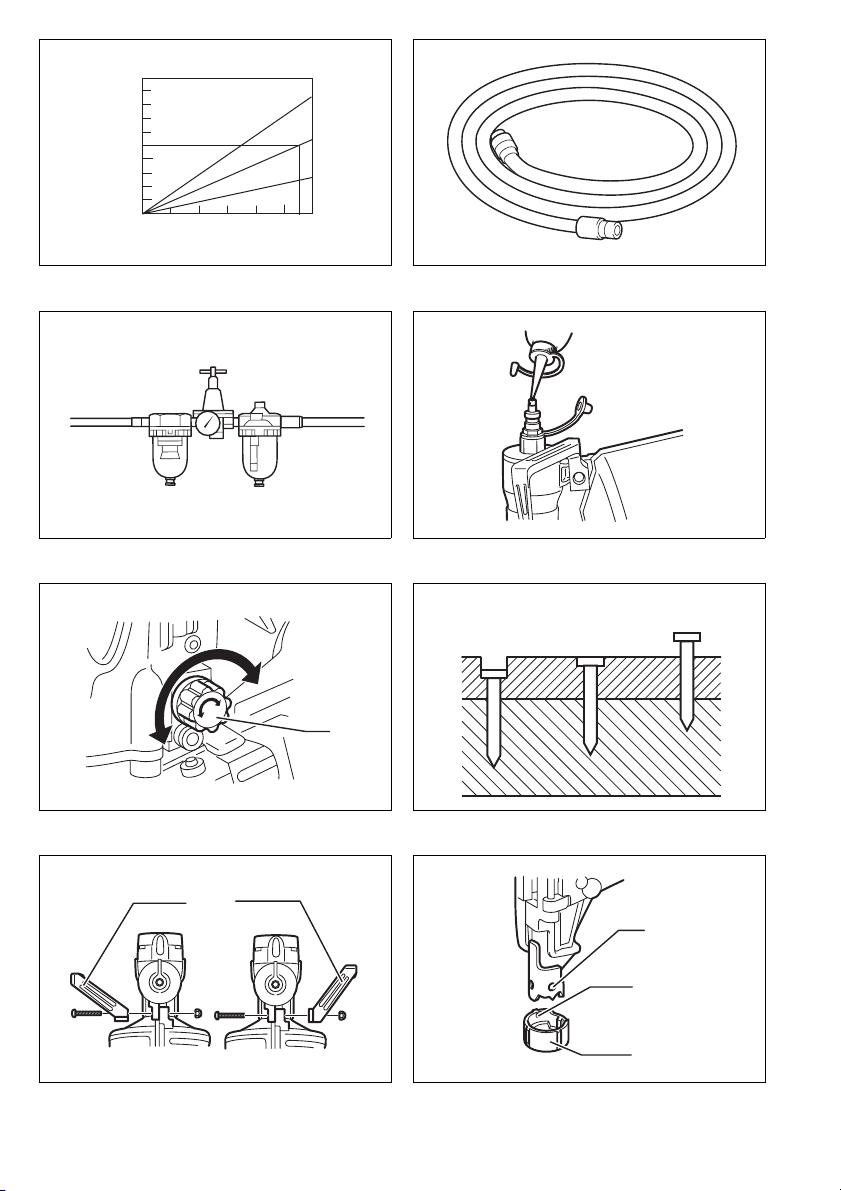
• Operate the tool within the specified air pressure of
0.98 – 2.26 MPa (9.8 – 22.6 bar) for safety and longer
tool life. Do not exceed the recommended max. operat-
ing pressure of 2.26 MPa (22.6 bar). The tool should
not be connected to a source whose pressure poten-
tially exceeds 3.39 MPa (33.9 bar).
• Make sure that the pressure supplied by the com-
pressed air system does not exceed the maximum
allowable pressure of the fastener driving tool. Set the
air pressure initially to the lower value of the recom-
mended allowable pressure (see SPECIFICATIONS).
• Never use the tool with other than compressed air. If
bottled gas (carbon dioxide, oxygen, nitrogen, hydro-
gen, air, etc.) or combustible gas (hydrogen, propane,
acetylene, etc.) is used as a power source for this tool,
the tool will explode and cause serious injury.
• Always check the tool for its overall condition and loose
screws before operation. Tighten as required.
• Make sure all safety systems are in working order
before operation. The tool must not operate if only the
trigger is pulled or if only the contact arm is pressed
against the wood. It must work only when both actions
are performed. Test for possible faulty operation with
nails unloaded and the pusher in fully pulled position.
• Check walls, ceilings, floors, roofing and the like care-
fully to avoid possible electrical shock, gas leakage,
explosions, etc. caused by striking live wires, conduits
or gas pipes.
• Use only nails specified in this manual. The use of any
other nails may cause malfunction of the tool.
• Never use fastener driving tools marked with the sym-
bol “Do not use on scaffoldings, ladders” for specific
application for example:
- when changing one driving location to another
involves the use of scaffoldings, stairs, ladders, or
ladder alike constructions, e.g. roof laths;
- closing boxes or crates;
- fitting transportation safety systems e.g. on vehicles
and wagons.
• Do not permit those uninstructed to use the tool.
• Make sure no one is nearby before nailing. Never
attempt to nail from both the inside and outside at the
same time. Nails may rip through and/or fly off, present-
ing a grave danger.
• Watch your footing and maintain your balance with the
tool. Make sure there is no one below when working in
high locations, and secure the air hose to prevent dan-
ger if there is sudden jerking or catching.
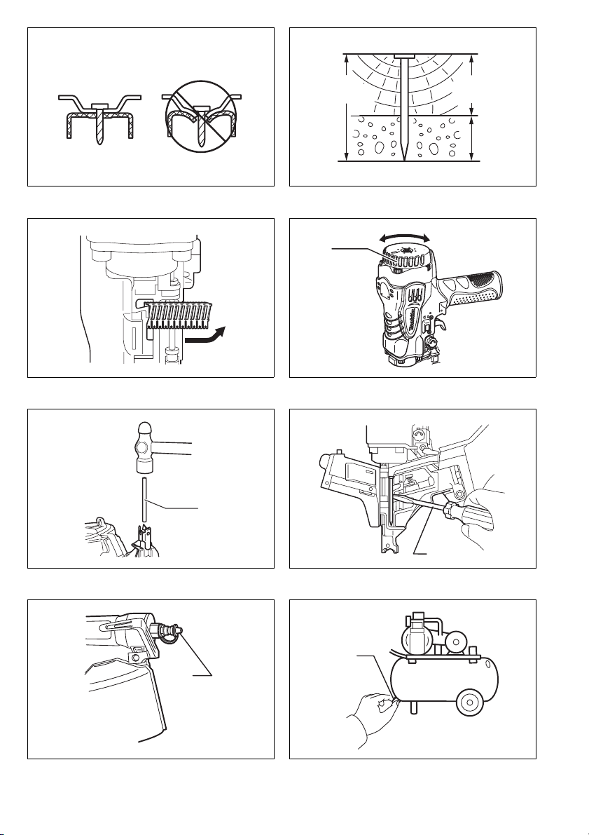
• On rooftops and other high locations, nail as you move
forward. It is easy to lose your footing if you nail while
inching backward. When nailing against perpendicular
surface, nail from the top to the bottom. You can per-
form nailing operations with less fatigue by doing so.
• A nail will be bent or the tool can become jammed if
you mistakenly nail on top of another nail or strike a
knot in the wood. The nail may be thrown and hit some-
one, or the tool itself can react dangerously. Place the
nails with care.
• Do not leave the loaded tool or the air compressor
under pressure for a long time out in the sun. Be sure
that dust, sand, chips and foreign matter will not enter
the tool in the place where you leave it setting.
• Do not point the ejection port at anyone in the vicinity.
Keep hands and feet away from the ejection port area.
• When the air hose is connected, do not carry the tool
with your finger on the trigger or hand it to someone in
this condition. Accidental firing can be extremely dan-
gerous.
• Handle the tool carefully, as there is high pressure
inside the tool that can be dangerous if a crack is
caused by rough handling (dropping or striking). Do not
attempt to carve or engrave on the tool.
• Stop nailing operations immediately if you notice some-
thing wrong or out of the ordinary with the tool.
• Always disconnect the air hose and remove all of the
nails:
9. When unattended.
10. Before performing any maintenance or repair.
11. Before cleaning a jam.
12. Before moving the tool to a new location.
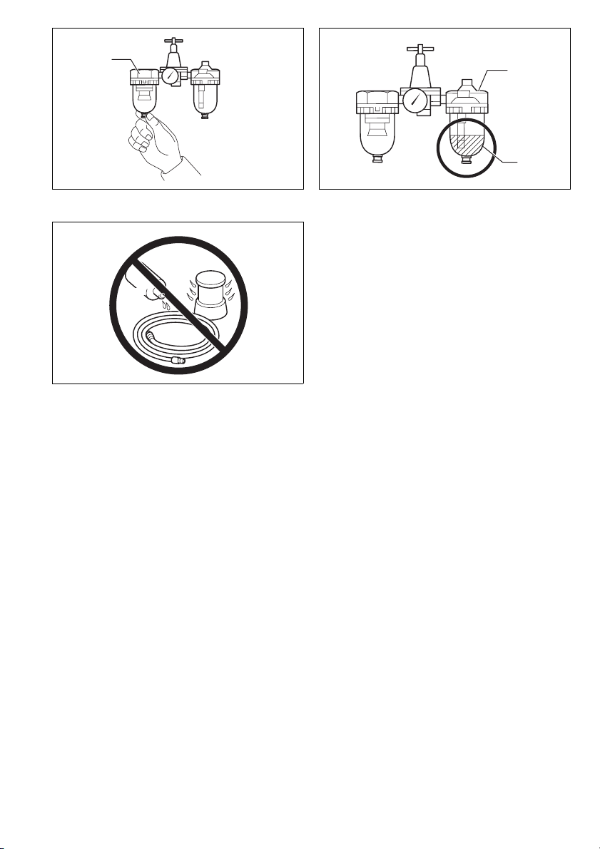
• Perform cleaning and maintenance right after finishing
the job. Keep the tool in tip-top condition. Lubricate
moving parts to prevent rusting and minimize friction-
related wear. Wipe off all dust from the parts.
• Do not modify tool without authorization from
Makita.
• Ask Makita’s Authorized service centers for periodical
inspection of the tool.

9
• To maintain product SAFETY and RELIABILITY, main-
tenance and repairs should be performed by Makita
Authorized Service Centers, always using Makita
replacement parts.
• Use only pneumatic tool oil specified in this manual.
• Never connect tool to compressed air line where the
maximum allowable pressure of tool cannot be
exceeded by 10%. Make sure that the pressure sup-
plied by the compressed air system does not exceed
the maximum allowable pressure of the fastener driving
tool. Set the air pressure initially to the lower value of
the recommended allowable pressure.
• Do not attempt to keep the trigger or contact element
depressed with tape or wire. Death or serious injury
may occur.
• Always check contact element as instructed in this
manual. Nails may be driven accidentally if the safety
mechanism is not working correctly.
SAVE THESE INSTRUCTIONS.
INSTALLATION
Selecting compressor (Fig. 1)
The air compressor must comply with the requirements
of EN60335-2-34.
The air compressor must comply with the requirements
of ANSI B19.3.
Select a compressor that has ample pressure and air
output to assure cost-efficient operation. The graph
shows the relation between nailing frequency, applicable
pressure and compressor air output.
Thus, for example, if nailing takes place at a rate of
approximately 55 times per minute at a compression of
1.76 MPa (17.6 bar), a compressor with an air output
over 50 liters/minute is required.
Pressure regulators must be used to limit air pressure to
the rated pressure of the tool where air supply pressure
exceeds the tool’s rated pressure. Failure to do so may
result in serious injury to tool operator or persons in the
vicinity.
Selecting air hose (Fig. 2)
Use a high pressure resistant air hose.
Use an air hose as large and as short as possible to
assure continuous, efficient nailing operation.
CAUTION:
• Low air output of the compressor, or a long or smaller
diameter air hose in relation to the nailing frequency
may cause a decrease in the driving capability of the
tool.
Lubrication
To insure maximum performance, install an air set (oiler,
regulator, air filter) as close as possible to the tool. Adjust
the oiler so that one drop of oil will be provided for every
30 nails. (Fig. 3)
When an air set is not used, oil the tool with pneumatic
tool oil by placing 2 (two) or 3 (three) drops into the air fit-
ting. This should be done before and after use. For
proper lubrication, the tool must be fired a couple of
times after pneumatic tool oil is introduced. (Fig. 4)
FUNCTIONAL DESCRIPTION
CAUTION:
• Always disconnect the air hose before adjusting or
checking function on the tool.
Adjusting the nailing depth (Fig. 5 & 6)
CAUTION:
• Always disconnect the hose before adjusting the depth
of nailing.
If nails are driven too deep, turn the adjuster clockwise. If
nails are driven too shallow, turn the adjuster counter-
clockwise.
The adjustable range is 0 – 6 mm. (One full turn allows
0.8 mm adjustment.)
Hook (Fig. 7)
CAUTION:
• Always disconnect the hose when hanging the tool
using the hook.
• Never hang the tool on a waist belt or like. Dangerous
accidental firing may result.
The hook is convenient for hanging the tool temporarily.
This hook can be installed on either side of the tool.
When changing the installation position, remove the
screw with a screwdriver. Install the hook on another side
for installation and then secure it with the screw.
Use the nose adapter (Fig. 8)
CAUTION:
• Always disconnect the hose before installing or remov-
ing the nose adapter.
If you like to protect the surface of workpiece, attach the
nose adapter of contact element.
When nailing workpieces with easily-marred surfaces,
use the nose adapter. To attach the nose adapter to the
contact arm, press it onto the contact arm as far as it will
go.
ASSEMBLY
CAUTION:
• Always disconnect the air hose before loading the
nailer.
Loading nailer
CAUTION:
• Make sure that the coil support plate is set to the cor-
rect step for used nails.
Disconnect the air hose from the tool. Select nails suit-
able for your work. Depress the latch lever and open the
magazine cap. (Fig. 9)
Select nails suitable for your work. Depress the latch
lever and open the magazine cap.
Lift and turn the coil support plate so that the arrow with
nail size indicated on the coil support plate will point to
the corresponding graduation increment marked on the
magazine. If the tool is operated with the coil support
plate set to the wrong step, poor nail feed or malfunction
of the tool may result. (Fig. 10)
Place the nail coil over the coil support plate. Uncoil
enough nails to reach the feed claw. Place the first nail in
the driver channel and the second nail in the feed claw.
Place other uncoiled nails on feeder body. Close the
magazine cap slowly until it lock after checking to see
that the nail coil is set properly in the magazine. (Fig. 11)

10
Connecting air hose
Slip the air socket of the air hose onto the air fitting on the
nailer. Be sure that the air socket locks firmly into position
when installed onto the air fitting. A hose coupling must
be installed on or near the tool in such a way that the
pressure reservoir will discharge at the time the air sup-
ply coupling is disconnected.
OPERATION
CAUTION:
• Make sure all safety systems are in working order
before operation.
1. To drive a nail, you may place the contact element
against the workpiece and pull the trigger, or
2. Pull the trigger first and then place the contact ele-
ment against the workpiece. (Fig. 12 & 13)
• No. (1) method is for intermittent nailing, when you wish
to drive a nail carefully and very accurately. No. (2)
method is for continuous nailing.
CAUTION:
• However when the tool is set to the “Intermittent Nail-
ing” mode, WITH THE TRIGGER HELD IN A HALF-
PULLED POSITION, an unexpected nailing could
occur, if contact element is allowed to re-contact
against the workpiece or the other surface under the
influence of recoil.
In order to avoid this unexpected nailing, perform as fol-
lows;
A. Do not place the contact element against the work-
piece with excessive force.
B. Pull the trigger fully and hold it on for 1 – 2 seconds
after nailing.
• For No. (1) method, set the change lever to the
position.
For No. (2) method, set the change lever to the
position.
After using the change lever to change the nailing
method, always make sure that the change lever is
properly set to the position for the desired nailing
method. (Fig. 14 & 15)
Nailing of steel plate (Fig. 16 & 17)
WARNING:
• Use 2.3 mm or less steel for C-shaped one.
The tool will bounce severely and a nail struck back,
causing serious injuries.
• Use hardened nails only for steel plate.
Using other purposed nails may cause serious injuries.
• When nailing, hold the tool so that it stands upright to
the driving surface.
Slanted nailing may cause nails to strike back, causing
serious injuries.
• When fastening a corrugated zinc plate on the C-
shaped steel, use 0.7 mm or less thick plate and
32 mm long hardened nails. Failure to do so may cause
nails to strike back, causing serious injuries.
• Do not use the tool for nailing on ceiling or roof.
Choose and use nails more than 10 mm longer than total
thickness of all workpiece to be fastened by referring to
the table below.
CAUTION:
• Depending on the hardness and total thickness of all
workpiece in combination to be fastened, enough fas-
tening may not be obtained. Nailing on steel plate to
excessive depth may extremely reduce the fastening
force. Before nailing, adjust the nailing depth properly.
• In the nailing on the steel plate, the driver may be
clogged due to susceptibility to wear. When it is worn,
sharpen it or replace it with a new one.
Nailing of concrete (Fig. 18)
WARNING:
• Use hardened nails only for concrete.
Using other purposed nails may cause serious injuries.
Do not nail directly on the concrete or do not use to fas-
ten directly the steel plate to the concrete. Failure to do
so may cause concrete fragments to fly off or nails to
strike back, causing serious injuries.
• When nailing, hold the tool so that it stands upright to
the driving surface.
Slanted nailing may cause concrete fragments to fly off
or nails to strike back, causing serious injuries.
• Do not use on the surface that objects hang from, such
as area where hangers for sewer pipe, dust pipe etc.
are set up.
Choose and use nails so that the penetration amount into
concrete ranges 10 mm – 15 mm by referring to the table
below.
CAUTION:
• Use this tool only for soft concrete built up not so long
before. Using on the hard concrete may cause nail
bending or nailing to insufficient depth.
• When the penetration amount into concrete comes to
more than 15 mm, nailing to the sufficient length may
not be obtained.
Cutting off the sheet (Fig. 19)
CAUTION:
• Always disconnect the hose before cutting off the
sheet.
Tear off the output sheet in the direction of the arrow
when using the sheet collated nails.
Air exhaust (Fig. 20)
Air exhaust direction can be changed easily by rotating
the exhaust cover. Change it when necessary.
Material thickness (mm) Nail length (mm)
10–27 38
15–30 45
15–38 50
Wood thickness
(mm) Nail length (mm) Concrete (mm)
25 38 Approx. 13
30 45 Approx. 15
35 50 Approx. 15

11
MAINTENANCE
CAUTION:
• Always disconnect the air hose from the tool before
attempting to perform inspection or maintenance.
Jammed nailer (Fig. 21 & 22)
CAUTION:
• Always disconnect the air hose and remove the nails
from the magazine before cleaning a jam.
When the nailer becomes jammed, do as follows:
Open the magazine cap and remove the nail coil. Insert a
small rod or the like into the ejection port and tap it with a
hammer to drive out the nail jamming from the ejection
port. Reset the nail coil and close the magazine cap.
Drain tool
Remove the hose from the tool. Place the tool so that the
air fitting faces down to the floor. Drain as much as possi-
ble.
Cleaning of tool
Iron dust that adhere to the magnet can be blown off by
using an air duster.
Cap (Fig. 23)
When not in use, disconnect the hose. Then cap the air
fitting with the cap.
Storage
When not in use, the nailer should be stored in a warm
and dry place.
Maintenance of compressor, air set and air hose
After operation, always drain the compressor tank and
the air filter. If moisture is allowed to enter the tool, it may
result in poor performance and possible tool failure.
(Fig. 24 & 25)
Check regularly to see if there is sufficient pneumatic oil
in the oiler of the air set. Failure to maintain sufficient
lubrication will cause O-rings to wear quickly. (Fig. 26)
Keep the air hose away from heat (over 60°C, over
140°F), away from chemicals (thinner, strong acids or
alkalis). Also, route the hose away from obstacles which
it may become dangerously caught on during operation.
Hoses must also be directed away from sharp edges and
areas which may lead to damage or abrasion to the hose.
(Fig. 27)
To maintain product SAFETY and RELIABILITY, repairs,
any other maintenance or adjustment should be per-
formed by Makita Authorized Service Centers, always
using Makita replacement parts.
ACCESSORIES
CAUTION:
• These accessories or attachments are recommended
for use with your Makita tool specified in this manual.
The use of any other accessories or attachments might
present a risk of injury to persons. Only use accessory
or attachment for its stated purpose.
If you need any assistance for more details regarding
these accessories, ask your local Makita service center.
• Nails
• Air hoses
• Safety goggles
ENG102-3
Noise
The typical A-weighted noise level determined according
to EN792:
Sound pressure level (LpA): 88 dB (A)
Sound power level (LWA): 101 dB (A)
Uncertainty (K): 3 dB (A)
Wear ear protection
ENG233-2
Vibration
The vibration emission value determined according to
EN792:
Vibration emission (
ah
)
: 4.0 m/s2
Uncertainty (K): 1.5 m/s2
ENG901-1
• The declared vibration emission value has been mea-
sured in accordance with the standard test method and
may be used for comparing one tool with another.
• The declared vibration emission value may also be
used in a preliminary assessment of exposure.
WARNING:
• The vibration emission during actual use of the power
tool can differ from the declared emission value
depending on the ways in which the tool is used.
• Be sure to identify safety measures to protect the oper-
ator that are based on an estimation of exposure in the
actual conditions of use (taking account of all parts of
the operating cycle such as the times when the tool is
switched off and when it is running idle in addition to
the trigger time).
ENH003-11
For European countries only
EC Declaration of Conformity
We Makita Corporation as the responsible
manufacturer declare that the following Makita
machine(s):
Designation of Machine: Construction Nailer
Model No./ Type: AN620H
are of series production and
Conforms to the following European Directives:
98/37/EC until 28th December 2009 and then with
2006/42/EC from 29th December 2009
And are manufactured in accordance with the following
standards or standardised documents:
EN792
The technical documentation is kept by our authorized
representative in Europe who is:
Makita International Europe Ltd.
Michigan Drive, Tongwell,
Milton Keynes, MK15 8JD, England
30th January 2009
Tomoyasu Kato
Director
Makita Corporation
3-11-8, Sumiyoshi-cho,
Anjo, Aichi, JAPAN
Other manuals for AN620H
1
Table of contents
Other Makita Nail Gun manuals

Makita
Makita AF601 User manual

Makita
Makita XNB02 User manual

Makita
Makita AN510H User manual

Makita
Makita AN923 User manual

Makita
Makita DBN500 User manual

Makita
Makita AN902 User manual

Makita
Makita DBN600Z User manual

Makita
Makita DBN500 User manual

Makita
Makita DBN500 Manual

Makita
Makita DPT350RFJ User manual

Makita
Makita PT001G User manual

Makita
Makita GN420C User manual

Makita
Makita AG090 User manual

Makita
Makita DPT350 User manual

Makita
Makita AN611 User manual

Makita
Makita AF600 User manual

Makita
Makita AF500HP User manual

Makita
Makita AF632 User manual

Makita
Makita BPT350 User manual

Makita
Makita AN942 User manual