Aventura VPO-411PC User manual

VPO-411PC/FC
User Manual
AVENTURA TECHNOLOGIES INC.
Version
7.52
VIEW PASS
http://www.BIO-GUARD.COM

VPO-411PC/FC
USER MANUAL

VPO-411 INTRODUCTION i
VPO-411 provides an extremely effective means of granting entry to personnel who need it, while maintaining the
security of the building. VPO-411 can reduce costs of guard services and re-keying lock-sets, while providing a higher level of
security. BIO-GUARD’s VPO-411 combines patented fingerprint verification technology with an industry-standard proximity card reader.
This ensures greater security for the card issuer and the card user. Requiring that the fingerprint of the person seeking entry
matches the identity of the cardholder eliminates access via lost or stolen proximity cards. Suitable for both standalone and
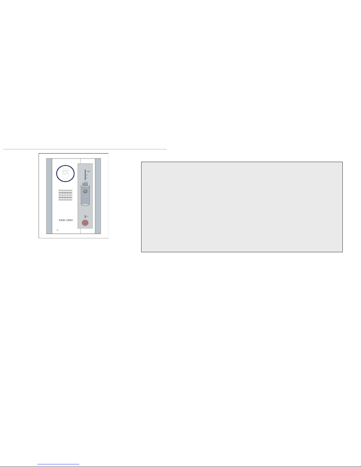
network use. The unit can operates in conjunction with administration software hosted on a PC (Optional). Once installed users
simply present their identification cards when entering the secure area and then touch a fingertip to the recessed area on top of
the unit.
VPO-411 offer the following advantages:
No keys to be lost or duplicated. If an access card is lost, or when an employee leaves the company, the card can
be removed from the system database, and would no longer provide access to the cardholder. Unlike keys, if cards are not
retrieved, the security of a facility can be maintained. Installation of card access saves the periodic costs of changing locksets,,
and redistributing keys to each employee. Unique cards are issued for each employee, for individual control, accountability, and
tracking of activity. Flexible control can be accomplished by allowing each person access to different areas and only at certain
times. Employees who have left can be removed from the system. Once they are removed, the employee no longer has access,
even though they may still have the access card.
An audit trail is provided for management tracking and reporting of who entered and/or left a particular area at a
particular time. Tracking of invalid attempts is also provided in many systems to allow management to determine if employees are
attempting to enter areas they are not permitted into, or whether employees are attempting to get into areas at the wrong time.
Access Control Applications:
Computer rooms, office areas, building entries, storage rooms, electrical
service rooms, data communications rooms, telephone closets, parking areas,
elevators, warehouses, nuclear facilities, and other areas are typically
protected by access control systems. Small and large companies have needs
for employee control.

VPO-411 INTRODUCTION ii
VPO-411 Series Are . . .
Durable
At the heart of VPO-411 fingerprint sensors is the optical module, featuring a virtually indestructible prism sensor. From the sensor surface to
the internal lens and electronic components, these sensors were designed to be strong and dependable to deliver consistent performance for
a wide range of applications.
VPO-411's were tested under extreme conditions, simulating the possible environments in which your applications may operate. These
system have been proven to perform in high-traffic and semi-outdoor conditions and resist exposure to:
Accurate
VPO-411 produce very high accuracy rates. An innovative optic design yields distortion-free images from which data points are used for
matching. High quality images mean greater precision, less false rejection, less false acceptance, and better overall performance. In a recent
independent test by International Biometric Group of major biometric products, VPO-411's sensor achieved 0.0% false acceptance and 0.0%
false rejection rates.
Maintenance-free
Unlike semiconductor-based sensors and competitive optical sensors in the market, VPO-411's sensor prism is made of a hard quartz-like
material that resists scratches, stress and corrosion. There are no coatings to maintain or disturb. Additionally, the optic parts are tightly
assembled so that if the sensors are ever dropped, there is no need for re-calibration.
Unique Features of VPO-411 Fingerprint Access Control System
•Access using Identification (one to many access) or Verification (one to one)
Group matching to speed up identification
•99 Timezones to control users access to premises using PLA-64 software
•8 operation modes to control the door operation
•Easy installation to direct connect to most door accessories
•RS-232, 422, TCP/IP network communication with optional RS422 Converter
and Ethernet communication
•PLA-64 Software using PC as Host for centralized enrollment, network
monitoring and control
•Secure password to protect unauthorized access to network
•User-defined function key as contingency means to access door

CONTENT
Introduction i 4
Introduction ii 5
CHAPTER 1 7
UNDERSTANDING THE VPO-411
VPO-411 SPECIFICATION 7
SENSOR & RFID SPECIFICATION 8
VPO-411 (FC/PC) 9
CONTROLLER LAYOUT 10
VPO-411 CONTROLLER LAYOUT 2 11
DIAGRAM (RS232) 12
NETWORK DIAGRAM (RS422) 13
NETWORK DIAGRAM 2 (RS422) 14
NETWORK DIAGRAM 2 (TCP/IP LAN) 15
NETWORK DIAGRAM 1 (TCP/IP WAN) 16
USING THE FINGERPRINT SCANNER 17
QUICK START
STARTING THE UNIT FOR THE FIRST TIME 1 18
STARTING THE UNIT FOR THE FIRST TIME 2 19
REGISTERING MASTER 20
OPERATING THE UNIT 21
CHAPTER 2 22
ADMINISTRATOR MODE
USER MENU IN DETAIL 23
ENTERING ADMINISTRATOR MENU 24
SYSTEM MENU 1
REGISTERING USER CARD 25
REGISTERING USER FINGERPRINT 26
REGISTERING USER CARD AND FINGERPRINT 27
SYSTEM MENU 2
DELETE USER 28
SYSTEM MENU 3
DELETING ALL USER 29
SYSTEM MENU 4
VERIFY USER 30
SYSTEM MENU 5
CHANGE MODE 31
CHANGE MODE CONTINUED 32
OPERATING THE UNIT
IN DIFFERENT MODE 33
SYSTEM MENU 6
RELOCK TIME 34
SYSTEM MENU 7
EVENT DISPLAY 35
EVENT CODE 36
SYSTEM MENU 8
TIME SETTING 37
SYSTEM MENU 9
DISPLAY TIME 38
SYSTEM MENU 10
ABOUT WIEGAND 39
ABOUT WIEGAND 40
WIEGAND SELECT 41
SYSTEM MENU 11
DEFAULT TIME 42
DEFAULT TIME 1 43
SYSTEM MENU 12
VPO_ADDRESS 44
SYSTEM MENU 13
USER LIST 45
SYSTEM MENU 14
FDA SECURITY LEVEL SETTING 46
SYSTEM MENU 15
VPO SYSTEM SETTING 47
SYSTEM MENU 16
CHANGE FINGERPRINT 48
SYSTEM MENU 17
EXIT 49
CHAPTER 3 50
EXTRA FEATURES AND CONTENTS
USING FUNCTION KEY 51
BATTERY BACKUP CONNECTION 52
TROUBLESHOOTING 53
Q&A 54
MAINTENANCE 55

CHAPTER 1
CHAPTER 1
UNDERSTANDING THE VPO-411
VPO-411PFC SPECIFICATION 7
SENSOR & RFID SPECIFICATION 8
VPO-411 (FC/PC) 9
CONTROLLER LAYOUT 10
VPO-411 CONTROLLER LAYOUT 2 11
DIAGRAM (RS232) 12
NETWORK DIAGRAM (RS422) 13
NETWORK DIAGRAM 2 (RS422) 14
NETWORK DIAGRAM 2 (TCP/IP LAN) 15
NETWORK DIAGRAM 1 (TCP/IP WAN) 16
USING THE FINGERPRINT SCANNER 17
QUICK START
STARTING THE UNIT FOR THE FIRST TIME 1 18
STARTING THE UNIT FOR THE FIRST TIME 2 19
REGISTERING MASTER 20
OPERATING THE UNIT 21

VPO-411 SPECIFICATION
VPO-411PFC SPECIFICATIONS
►User Registration:
◦VPO-411: 720 Users
►Transaction Memory Buffer
◦VPO-411: 8,192 Transactions / Unlimited
when networked with PC
►Up to 64 connections using RS422 converter
/ Unlimited using TCP/IP
►Separate Controller Type, IDC (Indoor
Controller)
►Audio Visual Indicator:
Red LED: Access denied / Green LED: Access
granted / with Voice Command
►FAR (False Acceptance Rate) = 0.00008 %
►FRR (False Rejection Rate) = 0.09 %
►Adjustable Fingerprint Recognition Level:
0~9(10 levels)
►Recognition Adjustment S/W (Factory Set)
►Compatible Cards: All HID RF Cards
►Networking Software (VPO-411 only)
◦PLA-64: Access Control Software
◦PLAT-4000: Access Control and Time &
Attendance Software
►Programming Method
◦IDC (Indoor Controller)
►Operation Mode
VPO-411(FC) has 6 Operating Modes
VPO-411(PC) has 5 Operating Modes
VPO-411FC

SENSOR & RFID SPECIFICATION
SENSOR SPECIFICATIONS
RESOLUTION 500dpi
VERIFICATION TIME Less than 1 second
ENCRYPTED DATA SIZE 400 bytes
SENSING AREA 13.6 x 16.2 mm
DIMENSIONS-OPTIC MODULE 21 x 32 x 63
DIMENSIONS – BOARD 34 x 93 mm
WEIGHT 28g (1oz)
OPERATING TEMPERATURE -0 to 50 C
OPERATING HUMIDITY Up to 90%
LIGHT SOURCE Red LED
SUPPLY VOLTAGE 5V DC
MAXIMUM SUPPLY CURRENT 270 mA standby
320 mA operating
HID MCM SPECIFICATIONS
Power supply:
10-28.5 VDC; Linear power supplies
recommended. Reverse voltage protection included.
Current requirements:
Average: 100 mA (12 VDC)
Peak: 120 mA (24 VDC)
Operating temperature:
-22°to 150°F (-30°to 65°C)
Operating humidity:
0-95% relative humidity non-condensing
Transmit frequency: 125 kHz
Excite frequency: 125 kHz
Cable distance:
Wiegand or Clock and Data interface: 500 feet (152 m)
RS-232 interface: 50 feet (15 m)
RS-422 interface: 4000 feet (1219 m)
VPO-411PC

VPO-411(FC/PC)
CAMERA
SENSOR START BUTTON
MICRO PHONE
SPEAKER PHONE
FINGER SENSOR
PROXIMITY READER
LED
BELL
IDC (INDOOR
CONTROLLER)
CONTROLLER

WIEGAND OUTPUT
RS 232 / RS 422
SENSOR
POWER
RESET SWITCH
READER 2
RELAY
ENTER KEY
ADDRESS DIAL
RJ45
MENU KEY
RS232/422 JUMPER
RESET
FUNCTION KEY
LCD
STATUS LED
CONTROLLER LAYOUT

VPO-411 CONTROLLER LAYOUT 2

DIAGRAM (RS232)
Default VPO Address is 1
Maximum distance using RS232 is 15m
Maximum number of connection using RS232
mode is 1 unit
It is necessary to use RS422 Converter when
connecting more than 1 unit
Make sure the jumper setting are set to RS232
mode
Figure 2 shows the RS232 connection to PC
Figure 1-2
Figure 1-2

NETWORK DIAGRAM (RS422)
NOTE:
Each unit must given an unique VPO address starting
from 1 – 16
Maximum number of connection using 1 RS-422
Converter is 16 units
Up to 4 RS422 Converters can be connected to PC,
thus connecting 64 units to PC
Maximum distance for RS232 connection is 15m
Maximum distance for RS422 is 1.2km and recommend
distance is 1km
Figure 2-1

NETWORK DIAGRAM 2 (RS422)
NOTE:
•Each unit must given an
unique VPO address
starting from 1 – 16
•Up to 4 RS422
Converters can be
connected to PC, thus
connecting 64 units to PC
•Maximum distance for
RS232 connection is 15m
•Maximum number of
connection using 1 RS-
422 Converter is 16 units
•PLA-64 supports up to 4
RS422 Converters and
total of 64 units
•Maximum distance for
RS422 is 1.2km and
Recommend distance is
1km.
•Must use Multi-Connector
when using more than 2
RS422 Converter
Figure 3-1
Some systems require longer distances or higher numbers of nodes than supported by RS-422. An RS-422 repeater can be placed in a system to
divide the load into multiple segments.

NETWORK DIAGRAM 2 (TCP/IP LAN)
Assign a static IP address to the Host (PC) and the TCP/IP Converter
1 Ethernet Converter supports maximum of 16 units.
PLA-64 supports up to 4 Ethernet Converters and total of 64 units
Each unit must be given a unique VPO Address from 1- 16. Refer to page 44 for more information.
It is not necessary to have real IP address for the Ethernet Converter when used in local network
Consult with Local Network Administrator before installation
Figure 4-1

NETWORK DIAGRAM 1 (TCP/IP WAN)
NOTE:
•Assign a static IP
address to the Host (PC)
and the TCP/IP Converter
.
• Each Ethernet Converter
must be given a Real IP
Address in order to be
used in Wide Area
Network
•Consult your ISP or
Network Administrator if
Ethernet Converter is
behind firewall.
•Maximum connections for
1 Ethernet Converter is 16
units.
•PLA-64 supports up to 4
Ethernet Converters and
total of 64 units
•Each unit must be given
a unique VPO Address
starting from 1 through 16
Figure 5-1

USING THE FINGERPRINT SCANNER
Improper way
Proper way
PROPER WAY:
• Make sure that the finger is aligned straight and level, with
the fingernail cuticle lined up with the horizontal lines on the
left and right sides of the sensor.
• Make sure the finger is covering the optic sensor
• Touch the automatic sensor when scanning
• Place finger firmly to sensor and hold until the red light
turns off. Removing the finger prematurely will have negative
effect.
• Try placing the finger deep inside the sensor if your
fingertip is damaged. Shown in Figure 6-1
• Lower the sensitivity level (Refer to page 45 and 46 for
more information on VPO System setting)
• Try applying skin moisturizer a few minutes before enrolling
to improve recognition.
IMPROPER WAY:
• Finger movement while scanning
• Finger is placed too far out
• Finger is touching the sensor too hard or light
• finger is too wet or dry
• finger is too dirty
• finger has too many cuts or abrasions
Refer Page 45 and 46 for more information on configuring
the sensor
CAUTION:
Sensor is sensitive to water and direct
sunlight
Do not operate with wet finger
NOTE:
•Finger must me
touching the
automatic sensor
• Make sure your
finger is dry before
using the scanner
• A bit of moisture
helps to speed up
verifying process
• Blow steam with
your mouth, if your
finger is very dry
Figure 6-1
Figure 6-2

STARTING THE UNIT FOR THE FIRST TIME QUICK START
When accessing VPO-411 for the first time, VPO-411 defaults to operation without an Administrator. If an Administrator template
exists in VPO-411’s database, VPO-411 prompts you to verify your identity by entering an ID number, and presenting a specific
fingerprint.
To access VPO-411’s Administration menu items:
If no Administrator has been enrolled: If Administrator has been enrolled:
MODE CONTENT
PRESS `*` KEY
MODE CONTENT
PRESS `*` KEY
1> ADD USER
1. Turn the power to the VPO-411 unit.
2. Following screen appears
VERIFY MASTER
ID : 12345678
Key in the Administrator ID and
press the # key. The following screen
should appear to verify the
administrators Fingerprint or Card
VERIFY MASTER
1:FP 2:CARD
1> ADD USER
VERIFY MASTER
PRESENT USER FP
Following screen appears and
now you’re in system menu
Place finger on the scanner
until the red light turns off and
remove finger
[ANY] 2002. 11.21
16: 10: 46 [THU]
Press * key to enter Administrator Mod
Press 1 to verify Master by Finger press
2 to verify Master with Card For now we
will press 1 to verify with finger
Press * key again to enter
Administrator Mode
Press * key once again to enter
Administrator Mode
Following screen appears and now
you’re in system menu
1. Turn the power to the VPO-411 unit.
2. Following screen appears
Choosing the Method to Access
Administration Menus
[ANY] 2002. 11.21
16: 10: 46 [THU]
Press * key enter Administrator mode
1
2
3
4
1-1
1-2
1-3 1-4
1-5

STARTING THE UNIT FOR THE FIRST TIME
-MENU -
[C/F] 2003. 02.11
16: 10: 46 [MON]
[C/F] 2003. 02.11
16: 10: 46 [MON]
_
MODE CONTENT
PRESS `*` KEY
1> ADD USER
Press * key
Press * key again
Press * key and you will enter menu system
1> ADD USER
2> DELETE USER
3> DELETE ALL
4> VERIFY USER
5> CHANGE MODE
6> RELOCK TIME
7> EVENT DIP
8> TIME SETTING
9> DIISPLAY TIME
10> WIEG SELECT
11> DEFAULT TIME
12> VPO_ADDRESS
13> USER LIST
14> FDA-SECURITY
LEVEL SETTING
15> VPO SECURITY
SETTING
16> CHANGE FP
17> EXIT
Navigation Keys
Forward Button
Previous Button
Enter Button
1
2
3
4

REGISTERING MASTE
R
1> ADD USER
[C/F] 2003. 02.11
16: 10: 46 [MON]
_
MODE CONTENT
PRESS `*` KEY
Press * key to enter Administrator
menu
Press * key gain
8
1> ADD USER
1:1FP / 2: 2FP
1> ADD USER
FP ID : 12345678
Press 1 to register 1 finger
Please refer more on this option in Page 26
Enter User PIN from 1 to 8 digits
and press the # key
1> ADD USER
PRESENT USER FP
1> ADD USER
- - OK - -
1> ADD USER
PRESENT USER FP
Place finger on the scanner until the
red light turns off and remove finger
AUTHORITY
1: MASTER 2: USER
1> ADD USER
ADD : SUCCESS !
Press 1 to register as Master
1> ADD USER
18> EXIT
1:YES 2:NO
Place finger on the scanner until the
red light turns off and remove finger
Registering Master finished
Go to system menu 18 and Press ‘#’ key exit
Press 1 to exit off system menu
Press * key once again to enter
Administrator menu
Now you’re in System Menu
Press # key to add Master
1
2
3
47
11
15
14
13
9
10
12
1> ADD USER
ID : 12345678
1> ADD USER
1: CD 2: FP 3: C+F
Enter user PIN from 1 to 8 digits and press
the # key
56
Press 2 to register finger
Place finger on the scanner again
and remove finger when the red
light turns off
This manual suits for next models
1
Table of contents
Popular Control System manuals by other brands

Pentair
Pentair IntelliSync 523404 quick start guide

Rittal
Rittal DET-AC III Slave Mounting, installation and operating instructions

Fly Sky
Fly Sky FS-T4B instruction manual

Fly Sky
Fly Sky FS-HW-G4P user manual

Foxtech
Foxtech Leo 2 manual

Intelligent Lighting Controls, Inc.
Intelligent Lighting Controls, Inc. LightLEEDer Operation manual