Aveo Engineering PosiStrobe Titania User manual

INSTALLATION MANUAL
PosiStrobe Titania
DOC.NO:AVE-PSPSYW-IM
©2018 Aveo Engineering Group, s.r.o. All rights reserved. The information contained within this
document must not be disclosed, copied or reproduced in whole or in part without prior written
permission from Aveo Engineering Group, s.r.o. Distribution of this document shall only be as stated
in Table 02 unless otherwise agreed by Aveo Engineering Group, s.r.o.

Page 2 of 11
PosiStrobe Titania
AVE-PSPSYW-IM
INSTALLATION MANUAL
Table of Contents
PART 0 MANUAL ADMINISTRATION................................................................................3
0.1 DOCUMENT APPROVAL..............................................................................................................3
0.2 AMENDMENT RECORD PROCEDURE .........................................................................................4
0.3 EFFECTED PAGES PROCEDURE ................................................................................................4
1. POSISTROBE TITANIA............................................................................................5
2. OPERATING INSTRUCTIONS ..............................................................................5
3. INSTALLATION SCHEMATIC / WIRING DIAGRAM.................................5
4. CONTROL & POWER INPUTS...............................................................................6
5. TECHNICAL SPECIFICATION ..............................................................................6
6. TECHNICAL DRAWING ...........................................................................................7
7. WIRING CHART ..........................................................................................................8
8. OPTICAL PERFORMANCE.......................................................................................9
9. EQUIPMENT LIMITATION...................................................................................10
10. CARE AND CLEANING OF YOUR AVEO ENGINEERING AVIATION
LIGHTS ..........................................................................................................................10
11. TESTING OF THE LIGHT BEFORE INSTALLATION.................................10
12. NOTES ON INSTALLATION .................................................................................11

Page 3 of 11
PosiStrobe Titania
AVE-PSPSYW-IM
INSTALLATION MANUAL
Part 0 Manual Administration
0.1 Document approval
This document has been established in accordance with an alternative procedure
to DOA approved under EASA AP429.
This installation manual is applicable for part numbers:
•PosiStrobe Titania AVE-PSPSYW-T01
Compiled by: 28. –Aug. - 2018
Petr Jaroš
Engineer, Aveo Engineering Group, s.r.o.
Approved by: 28. –Aug. - 2018
Georg Hartl
Head of DO, Aveo Engineering Group, s.r.o.

Page 4 of 11
PosiStrobe Titania
AVE-PSPSYW-IM
INSTALLATION MANUAL
0.2 Amendment Record procedure
The master copy of this document shall be kept electronically as a read only
document under the control of Aveo Engineering Group, s.r.o. as Master
Copy.
ALL amendments to this manual will initiate a raise of issue.
ALL raises of issue will be given a sequential Alphabetic Issue Ident
sequentially from 01 to 99 in Table 01 - Issue No: Column–Initial Issue of
Document will be “01”
ALL Issues of this document will be approved by Head of DO
0.3 Effected Pages Procedure
ALL pages affected by ANY raise of issue of this manual will be listed in Table
01 - Effected Pages Column.
The reason(s) for ALL raise of issue and description of change due to raise of
issue will be provided for ALL raises of issue in Table 01 - Details Column.
Changes from the previous issue are highlighted by YELLOW HIGHLIGHTING
over new content. AND YELLOW HIGHLIGHTING AND CROSSING OUT of
deleted content.
Example (CROSSING OUT)
Issue
No.
Details
Date
Effected
Pages
01
Initial Issue
28.Aug.2018
ALL
Table 01: Document Amendment Record Table
Page 5 of 11
PosiStrobe Titania
AVE-PSPSYW-IM
INSTALLATION MANUAL
1. PosiStrobe Titania
PosiStrobe Titania™ is the minimum EMI signature tail position and strobe light
for the aviation industry. This light provides performance much above the
required position and strobe per TSO standards.
2. OPERATING INSTRUCTIONS
When installed on the aircraft, using the aircraft’s power (14 or 28 volts), the
light will be at its maximum intensity. Operating Voltage range is 9-36VDC.
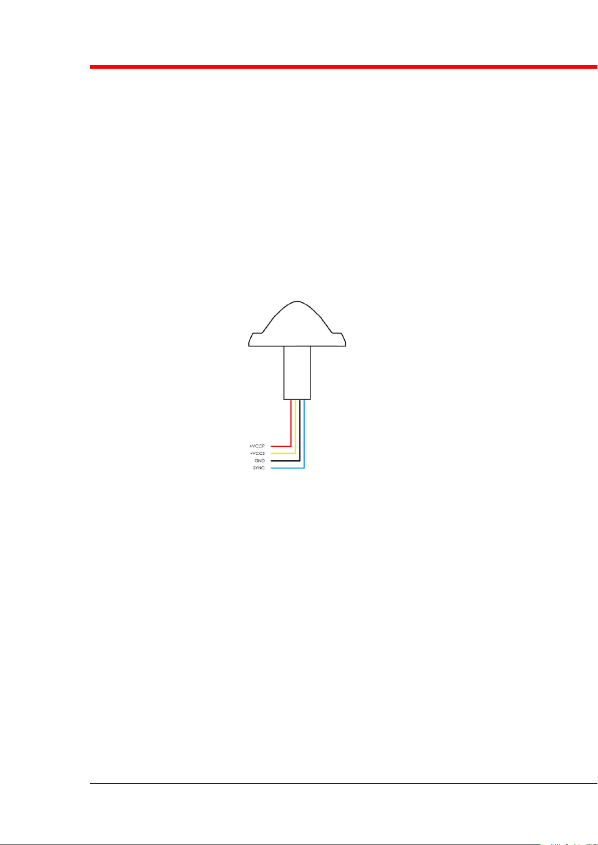
3. INSTALLATION SCHEMATIC / WIRING DIAGRAM
Wire type: multicores 22AWG, 600V insulation, 200°C rating;
Wire length: 12“ minimum (310mm minimum)

Page 6 of 11
PosiStrobe Titania
AVE-PSPSYW-IM
INSTALLATION MANUAL
4. CONTROL & POWER INPUTS
P/N: AVE-PSPSYW-T01
Pos/Strobe:
Red +14V / +28V, Nav/Pos
Yellow +14V / +28V, Anti-colision
Black Common 28 return VRTN
Blue Synchronization
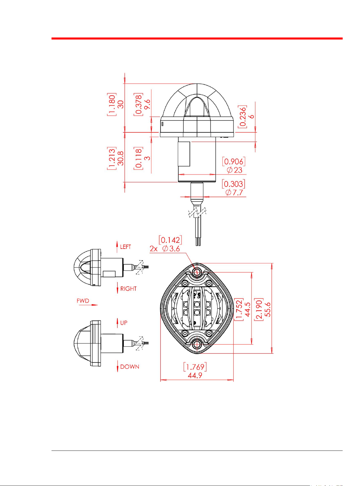
5. TECHNICAL SPECIFICATION
Dimensions: 56 mm x 45 mm
2.19” x 1.77”
Height:
Outside A/C skin 33 mm (1.30”)
Inside A/C 30 mm (1.18”)
Operating Voltage Range: 9 - 36 Vdc
Weight: 98 g (+/- 5g)
0.216 lb (+/- 0.18)
Output power:
–position (white steady) 4.1 W
–white strobe: 41.3 W
Input power (at 25°C and 85% DC-DC efficiency, @28VDC):
–position (white steady) 6.2 W
–white strobe: 53 W
Input current:
–position - white: 0.22 A
–white strobe: 1.9 A
Repetition Flash Rate of Strobe: 48 cycles per minute
Warm up time: not more than 20s
Low temperature slope start: not more than 60s
Ambient temperature: -55 °C..+85°C
Overheat protection: +85°C
Voltage protection:
a. Transcend voltage: 60V, both polarities
b. Under-voltage lockout: 9V , not more
c. Over-voltage lockout: 36V, not less
Page 7 of 11
PosiStrobe Titania
AVE-PSPSYW-IM
INSTALLATION MANUAL
6. TECHNICAL DRAWING
*dimensions in mm [inches]
Page 8 of 11
PosiStrobe Titania
AVE-PSPSYW-IM
INSTALLATION MANUAL
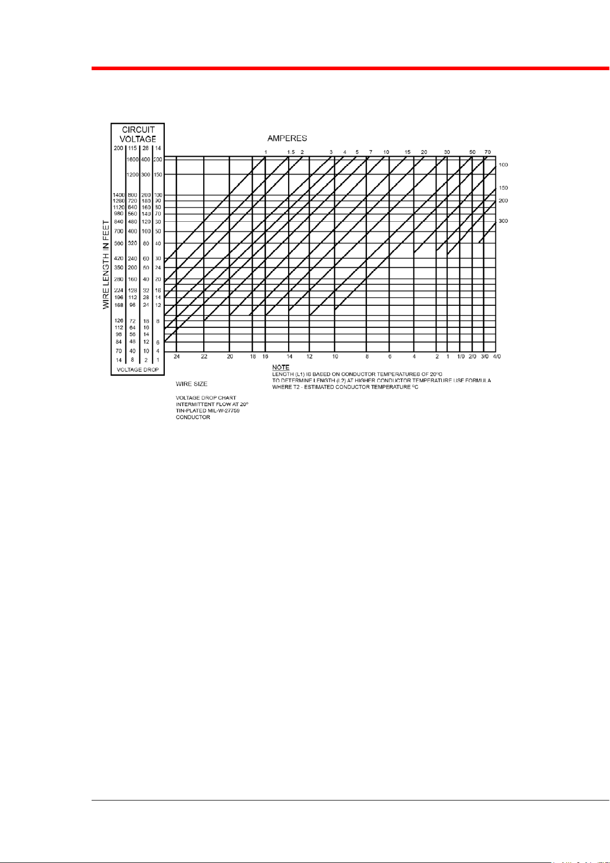
7. WIRING CHART

Page 9 of 11
PosiStrobe Titania
AVE-PSPSYW-IM
INSTALLATION MANUAL
8. OPTICAL PERFORMANCE
POSITION LIGHT
Test performed at 28V. Polar coordinates, 0°is forward direction.
Position H/V0. Full range 0-250cd
STROBE LIGHT
Test performed at 28V. Vertical plane at 180°horizontal point (rear). Effective
candelas.
Anti-collision H/V0. Full range 0-700cd

Page 10 of 11
PosiStrobe Titania
AVE-PSPSYW-IM
INSTALLATION MANUAL
9. EQUIPMENT LIMITATION
PosiStrobe should only be powered by 9-36VDC.
10. CARE AND CLEANING OF YOUR AVEO
ENGINEERING AVIATION LIGHTS
When you receive your Aveo Engineering Aviation Lights, they will have been
factory polished and ready to install on the aircraft.
If the lights require a deeper cleaning, they should be polished with a quality
lamb’s wool sheet and can also be used for deeper polishing. Under no
circumstances should any petroleum based product be used to clean the lights.
11. TESTING OF THE LIGHT BEFORE
INSTALLATION
All Aveo Aviation lights undergo rigorous testing prior to being released from
our engineering manufacturing department. This testing involves a burn-in
time as well as other function testing. No light is released for sale without
undergoing this extensive operational testing.
When you receive the PosiStrobe light, and wish to test the function of the
light prior to installation on your aircraft, please note the following:
1. Please review the written information that is enclosed in the packaging.
Warranty information as well as a cautionary note about power supply
removal is enclosed with each package.
2. Remove the light from the package.
Red +14V / +28V, Nav/Pos
Yellow +14V / +28V, Anti-colision
Black Common 28 return VRTN
Blue Synchronization
3. Testing of the function of the light can be done with a regular 28V/5A dc
power supply (not a battery charger).
Pos/strobe:
Connect the black wire to the ground (negative) leads of a power
supply, then connect the yellow or red wire to the positive (+) leads on
the power supply. The light should start flashing (yellow wire = anti-
collision light) or lighting (red wire = white steady). Connecting the blue
wires from each Aveo light together (and not to the ground or positive
terminals on the battery) should show that the lights are flashing
together and indicates the synchronization feature is working properly.

Page 11 of 11
PosiStrobe Titania
AVE-PSPSYW-IM
INSTALLATION MANUAL
IMPORTANT NOTES:
1. Under no circumstances should any power supply other than a 9-36
VDC, or a 28 volt battery be used to test the light. Do not use:
Battery chargers, battery back-up power devices, or other bench
avionics testing methods to test the aviation light. The light is
functional between 9 and 36 volts. Use of a battery charger or other
power unit to test the light will void the warranty and may damage the
light.
If you have any questions about the installation of the lights, please refer to
our web site: www.aveoengineering.com
12. NOTES ON INSTALLATION
Please use screw M3 (DIN912) or SHCS #6-32 or equivalent mounting screw for
the installation. Spread the tightening forces evenly around the mounting hole.
Stainless steel screw is recommended. Length depends upon placement location
on aircraft.
Table of contents
Other Aveo Engineering Lighting Equipment manuals

Aveo Engineering
Aveo Engineering THOR 36 DROP-IN User manual

Aveo Engineering
Aveo Engineering Hercules NXT User manual

Aveo Engineering
Aveo Engineering Nubion Plus User manual

Aveo Engineering
Aveo Engineering Exceleron DayLite User manual
 User manual")
Aveo Engineering
Aveo Engineering Nubion AVE-N09PANSNL-1WA Mod(2) User manual

Aveo Engineering
Aveo Engineering Atlas NXT User manual


