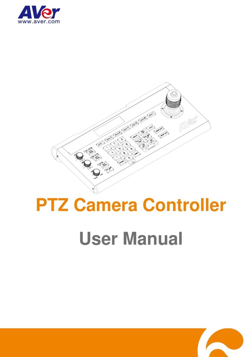
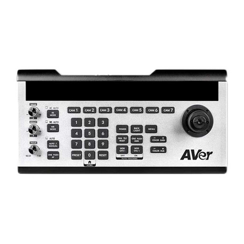
AVer CL01 User manual

CL01 PTZ Camera Controller
—User Manual —

Warning
To reduce risk of fire or electric shock, do not expose this appliance to rain or moisture.
Warranty will be void if any unauthorized modifications are done to the product.
Do not drop the device it to physical shock.
Use correct power supply voltage to avoid damaging camera.
Do not place the device where the cord can be stepped on as this may result in fraying or
damage to the lead or the plug.
Hold the both side of the device with both hands to move the device. Do not grab one side
of device to move the device.
Federal Communication Commission Interference Statement
This device complies with Part 15 of the FCC Rules. Operation is subject to the following two
conditions: (1) This device may not cause harmful interference, and (2) this device must
accept any interference received, including interference that may cause undesired operation.
This equipment has been tested and found to comply with the limits for a Class B digital device,
pursuant to Part 15 of the FCC Rules. These limits are designed to provide reasonable
protection against harmful interference in a residential installation. This equipment generates,
uses and can radiate radio frequency energy and, if not installed and used in accordance with
the instructions, may cause harmful interference to radio communications. However, there is
no guarantee that interference will not occur in a particular installation. If this equipment
does cause harmful interference to radio or television reception, which can be determined by
turning the equipment off and on, the user is encouraged to try to correct the interference by
one of the following measures:
- Reorient or relocate the receiving antenna.
- Increase the separation between the equipment and receiver.
- Connect the equipment into an outlet on a circuit different from that to which the receiver is
connected.
- Consult the dealer or an experienced radio/TV technician for help.
FCC Caution: Any changes or modifications not expressly approved by the party responsible
for compliance could void the user's authority to operate this equipment.
VCCI-B
この装置は、クラスB機器です。この装置は、住宅環境で使用することを 目的としていますが、この
装置がラジオやテレビジョン受信機に近接して使用される と、受信障害を引き起こすことがあります。
取扱説明書に従って正しい取り扱いをして下さい。
(注)本製品同梱の電源ケーブルは、本製品同梱の電源アダプタでのみ使用してください。 本製品同
梱の電源ケーブルは、他の電気機器では使用できません。
기종별
사용자안내문
B급기기
(가정용 방송통신기자재)
이기기는 가정용(B 급) 전자파적합기기로서
주로 가정에서 사용하는 것을 목적으로 하며,
모든 지역에서 사용할 수있습니다.

DISCLAIMER
No warranty or representation, either expressed or implied, is made with respect to the
contents of this documentation, its quality, performance, merchantability, or fitness for a
particular purpose. Information presented in this documentation has been carefully checked
for reliability; however, no responsibility is assumed for inaccuracies. The information
contained in this documentation is subject to change without notice.
In no event will AVer Information Inc. be liable for direct, indirect, special, incidental, or
consequential damages arising out of the use or inability to use this product or documentation,
even if advised of the possibility of such damages.
TRADEMARKS
“AVer” is a trademark owned by AVer Information Inc. Other trademarks used herein for
description purpose only belong to each of their companies.
COPYRIGHT
©2023 AVer Information Inc. All rights reserved. | November 21, 2023
All rights of this object belong to AVer Information Inc. Reproduced or transmitted in any form
or by any means without the prior written permission of AVer Information Inc. is prohibited. All
information or specifications are subject to change without prior notice.

More Help
For FAQs, technical support, software and user manual download, please visit:
Headquarters
Download Center: https://www.aver.com/download-center
Technical Support: https://www.aver.com/technical-support
USA Branch Office
Download Center: https://www.averusa.com/pro-av/support
Technical Support: https://averusa.force.com/support/s/contactsupport
Europe Branch Office
Download Center: https://www.avereurope.com/download-center
Technical Support: https://www.avereurope.com/technical-support
Contact Information
Headquarters
AVer Information Inc.
https://www.aver.com
8F, No.157, Da-An Rd., Tucheng Dist., New Taipei City 23673, Taiwan
Tel: +886 (2) 2269 8535
USA Branch Office
AVer Information Inc., Americas
https://www.averusa.com
668 Mission Ct., Fremont, CA 94539, USA
Tel: +1 (408) 263 3828
Toll-free: +1 (877) 528 7824
Technical support: support.usa@aver.com
Europe Branch Office
AVer Information Europe B.V.
https://www.avereurope.com
Westblaak 134, 3012 KM, Rotterdam, The Netherlands
Tel: +31 (0) 10 7600 550
Technical support: eu.rma@aver.com
Japan Branch Office
アバー・インフォメーション株式会社
https://jp.aver.com
〒160-0023 日本東京都新宿区西新宿 3-2-26 立花新宿ビル 7 階
Tel: +81 (0) 3 5989 0290
テクニカル・サポート: https://jp.aver.com/technical-support
Vietnam Branch Office
Công ty TNHH AVer Information (Việt Nam)
Tầng 5, 596 Nguyễn Đình Chiểu, P.3, Quận 3,
Thành phốHồChíMinh 700000, Việt Nam
Tel: +84 (0)28 22 539 211

Contents
Warning ......................................................................................................................2
Overview.....................................................................................................................1
Parts Info..................................................................................................................1
Dimensions...............................................................................................................1
Connections...............................................................................................................2
Keyboard....................................................................................................................3
Set up Your CL01 PTZ Camera Controller...............................................................6
Joystick Operation....................................................................................................6
Control More Than 7 Cameras.................................................................................6
Menu ........................................................................................................................7
Specifications ............................................................................................................9
Appendix..................................................................................................................10
VISPA over IP Settings...........................................................................................10
Control Command ..................................................................................................10
Query Command....................................................................................................11

1
Overview
Parts Info
Back panel
1. Micro USB Port (for firmware upgrade)
2. RS-422 / RS-485 Port
3. RS-232 Port
4. LAN Port
5. DC Power Jack
Dimensions

2
Connections
Connect your controller to a power outlet using the included power plug for your country or region.
Make sure your controller and PTZ cameras are connected to the same network.
RS-422 / RS-485 port connection table:
RS-422
Camera Controller
Camera
T+
R+
T-
R-
R+
T+
R-
T-
RS-485
Camera Controller
Camera
T+
RS-485 A+
T-
RS-485 B-

3
Keyboard
Name
Function
1. Light Sensor
for Backlit Keyboard
Make sure this area isn’t covered when you use your controller in low
light conditions. Turn backlit keyboard on or off in: Menu > System
Setting > Backlight.
2. LED Display
Shows the relevant menu and camera information.
3. CAM1 - CAM7
Switch to a camera you want to operate.
Make sure you have defined the camera by entering its IP address
and port number in: Menu > Ethernet Setting.
4. Joystick
Pan, tilt and zoom a camera.
Move through the menu.
Confirm a selection by moving right or pressing the top button.
5. Control Knobs
Value / R Knob: Adjust exposure or red gain value.
Bright / B Knob: Adjust exposure or blue gain value.
Focus Knob: Adjust focal length. Using the focus knob will change
your camera’s focus mode to Manual mode.

4
6. Auto Exposure
With each press, cycle through 5 exposure modes (Auto > Manual >
Shutter Priority > Iris Priority > Brightness Priority).
The AUTO indicator will light up to confirm that your camera is in
Auto mode.
Adjust Value/R knob and Bright/B knob accordingly:
AE Mode
Value
Bright
Auto
-
Gain compensation
Manual
Shutter
Iris
Shutter Priority
Shutter
Gain compensation
Iris Priority
Iris
Gain compensation
Brightness Priority
-
Brightness
7. White Balance
With each press, switch between Auto mode and Manual mode.
The AUTO indicator will light up to confirm that your camera is in
Auto mode.
Adjust Value/R knob and Bright/B knob accordingly:
WB Mode
Red
Blue
Auto
-
-
Manual
Red gain
Blue gain
8. Autofocus
Auto/Manual: With each press, switch between Auto mode and
Manual mode.
The AUTO indicator will light up to confirm that your camera is in
Auto mode.
One Push AF: Press to autofocus once.
9. Number Pad & Preset
To save a preset: Press PRESET until it flashes, then a number
(0-9), then PRESET again to save the preset position.
Example: Pressing PRESET + 1 + 2 + PRESET will save preset 12.
To load a preset: Press a number (0-9), then PRESET to load a
preset.
Example: Pressing 1 + 2 + PRESET will load preset 12.
To delete a preset: Press RESET until it flashes, then a number
(0-9), then RESET again to delete the preset position.
Example: Pressing RESET + 1 + 2 + RESET will delete preset 12.

5
10. Camera Functions
Power:
Press Power and the indicator lights of CAM1 - CAM7 will flash to
confirm their status.
Color
Status
Green
Normal
White
Standby
No light
No camera connected or status unavailable
Press Power and CAM1 - CAM7 to turn the camera on or off.
Backlight: Turn backlight compensation (BLC) on or off.
Menu: Press and hold for 3 seconds to open the menu. Short press
again to close the menu.
Pan-Tilt Reset: Reset the pan-tilt position.
One Push AWB: Adjust auto white balance once.
WDR Off / -: Turn off or decrease wide dynamic range (WDR). Or
Press and hold for 3 seconds to turn off auto-tracking.
WDR On / +: Turn on or increase wide dynamic range (WDR). Or
Press and hold for 3 seconds to turn on auto-tracking.
Color Gain: Increase or decrease the color gain value.
Color Hue: Increase or decrease the color hue value.

6
Set up Your CL01 PTZ Camera Controller
Joystick Operation
Action
Function
Right
Enter, move to, or confirm the selection.
Left
Exit the selection or go back to the previous selection.
Up
Move through the menu or decrease a value.
Down
Move through the menu or increase a value.
Top button
Enter or confirm the selection.
Control More Than 7 Cameras
Configure the CAM7 button in the menu to control up to 255 cameras.
To configure the CAM7 button for additional cameras:
1. Press and hold the menu button for 3 seconds to open the menu.
2. Go to 3. Ethernet Setting > 1. Channel > select CAM7 > disable 4. Lock.
3. 1. Channel: CAM7 will now read 1. Channel: CAM007.
4. Go to 1. Channel: CAM007. Use the joystick or number pad to specify a number for your camera.
To switch to additional cameras:
1. Short press the menu button again to close the menu.
2. Press the camera number using the number pads, then press the CAM7 button to control the
camera.

7
Menu
Press and hold the menu button for 3 seconds to open the menu. Short press again to close the menu.
Move the joystick right to enter, move to or confirm the selection.
System Setting
Item
Description
1. Language: English
Change the menu language to English, Traditional
Chinese or Simplified Chinese.
2. LED brightness: Normal
Set the LED display brightness of the controller to Normal,
Low or High.
3. Backlight: On
Set the Backlight button to On, Auto or Off.
4. Joystick sensitive: 3
Scroll down
Adjust the joystick sensitivity. When the sensitivity is set to
high, a small swinging amplitude can produce fast pan-tilt
movements.
5. Auto standby: Off
Scroll up
Set the length of time before the controller enters standby
mode.
6. ItselfIP: 192.168.000.088:52381
Enter your camera’s IP address and port number.
The default is 192.168.001.088: 52381.
Use the number pad (0-9) to enter the IP address and
port number.
7. Factory default
Reset the controller to factory default settings.
8. About keyboard
Displays controller information such as firmware version
and MAC address.
COM Setting
Item
Description
1. Channel: CAM1
Select a camera to set up.
2. Address: 1
Enter the address based on your protocol.
Protocol
Address value
Visca1
1-7
SonyVisca2
1-7
Pelco-P
1-7, other
Pelco-D
1-7, other
If the address is set to other, edit the address by doing the
following: Close the menu, then press a number, then your
camera button.
Example: Pressing 1+ 2+ CAM1 will change the CAM1 address
to 12.

8
3. Baud rate: 9600
Specify the rate at which bits are transmitted.
4. Protocol: Visca
Set the protocol to Visca, SonyVisca, Pelco-P or Pelco-D.
1:
VISCA
Serial port (RS-232/422/485) : VISCA
UDP VISCA
2:
Sony VISCA
IP: VISCA over IP
Ethernet Setting
Item
Description
1. Channel: CAM1
Select a camera to set up Ethernet.
2. Cam IP: 192.168.001.100
Enter the IP address using the number pad (0-9).
The cursor will move to the next field automatically after 3
digits.
Or press RESET to manually move to the next field.
Press PRESET to clear the field.
3. Port: 52381
Enter the port number using the number pad (0-9).
Password Setting
Item
Description
1. Password enable: disable
Enable or disable password.
When password is enabled, enter the password using the number
pad (0-9) before opening the menu.
2. Modify password
Change your password.

9
Specifications
I/O Port
RS-422/RS-485 Port
4-pin terminal
RS-232 Port
DB 9-pin male interface
LAN Port
(All communication ports can work
at the same time.)
RJ-45 female port
Power Plug
JEITA type-4 female
Upgrade Port
Micro USB female port
Camera Control
Max Support
255 PTZ cameras
Control Protocol
VISCA , PELCO P/D
Display Screen
OLED screen
Camera Channel
7
Knobs
3
Joystick
1
Control Signal Format
Baud Rate
2400bps, 4800bps, 9600bps, 19200bps, 38400bps
Data Bit
8 bits
Stop Bit
1 bit
Parity Bit
None
Ethernet Protocol
UDP/TCP/IP
Power
Rated Voltage
DC 12V
Rated Current
0.3A max, 3.6W
Power Consumption
24W
Physical
Working Temperature
0°C - 40°C (32°F - 104°F)
Storage Temperature
-20°C - +60°C (-4°F - 140°F)
Working temperature
Indoor
Dimension Size (L*W*H )
350mm x 173mm x 99mm
G.W (kg)
2.5kg
Packing Accessories
User manual / 4-pin terminal / power adapter / power jack
transfer cable

10
Appendix
VISPA over IP Settings
Interface
RJ-45 10BASE-T / 100BASE-TX / 1000BASE-T
Internet protocol
IPv4
Transport protocol
UDP
IP address
Your controller’s IP address
Port address
53669
Control Command
Command
Function
Command Package
Note
Panel System
Setting
Language
81 01 01 01 2p FF
English (0), TC (1),
SC(2)
LED Brightness
81 01 01 02 2p FF
L (0) / Normal (1) /
Hight (2)
Backlight
81 01 01 03 2p FF
off (0), on (1), auto (2)
Joystick sensitive
81 01 01 04 2p FF
1~7
Panel Channel
Setting
Set Channel IP
81 01 02 02 0m 0n 0p
0q 0r 0s 0t 0u 0v 0w
FF
IP = pqrstuvw, mn =
Channel No.(01~FF)
Set Channel port
81 01 02 03 0m 0n 0p
0q 0r 0s FF
Port = pqrs, mn =
Channel No.(01~FF)
Panel Com
Setting
Address
81 01 03 01 0m 0n 2p
FF
1~7, mn = Channel
No.(01~FF)
Baud rate
81 01 03 02 0m 0n 2p
FF
2400(1), 4800(2),
9600(3), 19200(4),
38400(5), mn =
Channel No.(01~FF)
Protocol
81 01 03 03 0m 0n 2p
FF
Visca (1), SonyVisca
(2), Pelco-P (3),
Pelco-D (4), mn =
Channel No.(01~FF)
Panel Control
Cmd
Select Control
Channel
81 01 04 01 0m 0n
FF
mn = Channel
No.(01~FF)

11
Query Command
Command
Command Package
Return Package
Note
PANEL_LanguageInq
81 09 01 01 FF
90 50 0p FF
English (0), TC (1), SC
(2)
PANEL_LED
Brightness_Inq
81 09 01 02 FF
90 50 0p FF
L (0) / Normal (1) /
Hight (2)
PANEL_Backlight_Inq
81 09 01 03 FF
90 50 0p FF
off (0), on (1), auto (2)
PANEL_Joystick
sensitive_Inq
81 09 01 04 FF
90 50 0p FF
1~7
PANEL_CurrentChann
el_Inq
81 09 02 01 FF
90 50 0m 0n FF
mn=Channel
No.(01~FF)
PANEL_CurrentChann
el IP_Inq
81 09 02 02 FF
90 50 0p 0q 0r 0s 0t 0u
0v 0w FF
IP = pqrstuvw
PANEL_CurrentChann
el port_Inq
81 09 02 03 FF
90 50 0p 0q 0r 0s FF
Port = pqrs
PANEL_Address_Inq
81 09 03 01 FF
90 50 0p FF
1~7
PANEL_Baudrate_Inq
81 09 03 02 FF
90 50 0p FF
2400(1), 4800(2),
9600(3), 19200(4),
38400(5)
PANEL_Protocol_Inq
81 09 03 03 FF
90 50 0p FF
Visca (1),
SonyVisca(2),
Pelco-P(3), Pelco-D(4)
Other manuals for CL01
2
Table of contents
Other AVer Controllers manuals