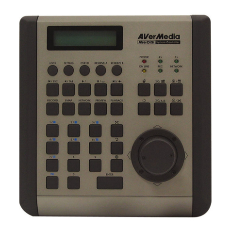
Avermedia AVerDiGi User manual

AVerMedia®
AVerDiGi
System Controller Pro
User Manual
Oct. 2009

DISCLAIMER
No warranty or representation, either expressed or implied, is made with respect to the
contents of this documentation, its quality, performance, merchantability, or fitness for a
particular purpose. Information presented in this documentation has been carefully
checked for reliability; however, no responsibility is assumed for inaccuracies. The
information contained in this documentation is subject to change without notice.
In no event will AVerMedia be liable for direct, indirect, special, incidental, or
consequential damages arising out of the use or inability to use this product or
documentation, even if advised of the possibility of such damages.
TRADEMARKS
AVerMedia, being authorized AVerMedia INFORMATION, Inc. to use, is registered
trademarks of AVerMedia TECHNOLOGIES, Inc. IBM PC is a registered trademark of
International Business Machines Corporation. Macintosh is a registered trademark of
Apple Computer, Inc. Microsoft is a registered trademark and Windows is a trademark of
Microsoft Corporation. All other products or corporate names mentioned in this
documentation are for identification and explanation purposes only, and may be
trademarks or registered trademarks of their respective owners.
COPYRIGHT
2009 by AVerMedia®INFORMATION, Inc. All rights reserved. No part of this publication
may be reproduced, transmitted, transcribed, stored in a retrieval system, or translated
into any language in any form by any means without the written permission of AVerMedia®
TECHNOLOGIES, Inc.

TABLE OF CONTENTS
CHAPTER 1 INTRODUCTION............................................................................1
1.1 Hardware Introduction............................................................................................................... 1
1.1.1 Left Side.......................................................................................................................... 1
1.1.2 Rear Side ........................................................................................................................ 1
1.1.3 Familiarizing with System Controller Panel Buttons........................................................ 2
1.2 Hardware Installation................................................................................................................. 5
1.2.1 Connecting with the DVR Server ................................................................................... 5
1.2.2 Connect a PTZ Camera to System Controller Pro......................................................... 5
CHAPTER 2 OPERATING THE SYSTEM CONTROLLER PRO........................6
2.1 Using the System Controller for the First Time.......................................................................... 6
2.1.1 Switching to USB DVR Mode......................................................................................... 7
2.2 Familiarizing with LCD Screen................................................................................................. 8
2.3 Operating the LCD Menu......................................................................................................... 9
2.4 Select a Camera .....................................................................................................................11
2.5 Locking System Operation..................................................................................................... 12
2.6 Trigger the Alarm Button ........................................................................................................ 13
2.7 To Playback the Recorded File .............................................................................................. 14
2.8 To View the Emap .................................................................................................................. 16
2.9 PTZ Operation......................................................................................................................... 17
2.9.1 Using the Joystick to Operate the PTZ Camera............................................................ 17
2.9.2 To Focus the Object ...................................................................................................... 18
2.9.4 Setup preset position and Use Preset........................................................................... 19
Setup Preset Position.................................................................................................... 19
Using the Preset Button ................................................................................................ 19
2.9.5 Enabling the AutoPan.................................................................................................... 20
2.9.6 Using Digital Zoom........................................................................................................ 22
2.10 Multi-Functions Menu........................................................................................................... 23
2.10.1 Select a Monitor Layout................................................................................................. 23
2.10.2 Camera Setup............................................................................................................... 24
Enable a Camera ......................................................................................................... 24
Enable a Camera View.................................................................................................. 25
Adjusting the Hue.......................................................................................................... 26
Adjusting the Saturation................................................................................................ 27
Adjusting the Brightness................................................................................................ 28

Adjusting the Contrast................................................................................................... 29
Enable the De-interlace................................................................................................. 30
Trigger the Relay of IP Camera..................................................................................... 31
2.10.3 Server Setup ................................................................................................................. 32
Start Recording.............................................................................................................. 32
Stop Recording.............................................................................................................. 33
Network Time Synchronization...................................................................................... 34
Open Event Log Viewer ................................................................................................ 34
2.10.4 Sound Setup.................................................................................................................. 35
2.10.5 Controller Setup ............................................................................................................ 36
Set a Password for System Controller .......................................................................... 36
Change the Password of the System Controller ........................................................... 38
Set the Timer................................................................................................................. 40
Adjusting the Brightness of LCD Screen....................................................................... 41
Adjusting the Contrast of LCD Screen .......................................................................... 42
Enable/disable Code Number Display .......................................................................... 43
Enable/disable Button Confirmation.............................................................................. 44
Viewing System Version Information............................................................................. 45
CHAPTER 3 OPERATING IN PTZ 485 MODE .................................................46
3.1 Switching to the PTZ 485 Mode............................................................................................. 46
3.2 Select the Protocol of the PTZ Camera ................................................................................. 48
3.3 Setup the Baudrate of the PTZ Camera ................................................................................ 49
3.4 Controller Setup..................................................................................................................... 50
Set a Password for System Controller .......................................................................... 50
Change the Password of the System Controller ........................................................... 52
Set the Timer................................................................................................................. 54
Adjusting the Brightness of LCD Screen....................................................................... 55
Adjusting the Contrast of LCD Screen .......................................................................... 56
Viewing System Version Information............................................................................. 57

1
Chapter 1 Introduction
The AVerDiGi System Controller Pro provides user an easy way to operate DVR server (NV/SA series).
1.1 Hardware Introduction
1.1.1 Left Side
Function Description
(1) USB Port 2 * USB ports for connection of keyboard, mouse, or USB flash memory.
(2) Audio Input For audio input device connection such as microphone.
(3) Audio Output For audio output device connection such as speaker.
i
- The audio input and output device has its own power supply is necessary.
- The audio input and output port act as the audio input and output port on the DVR
system.
1.1.2 Rear Side
Function Description
(1) RS485 Port For connection of Pelco-D/P PTZ camera
(2) Power Supply
Port For AC power adaptor connection.

2
1.1.3 Familiarizing with System Controller Panel Buttons
System Controller Panel figure
Function Description
(1) (Lock) To lock panel buttons and all operations are lock. Press it to lock and press
again to un-lock. If the system password has been set, please enter the
password to un-lock (see also Chapter 2.5)
(2) (Power) Lights up when unit is power on.
(3)
(Panic Button)
To trigger the alarm buttons that user has defined (see also Chapter 2.6).
To setup alarm button, please refer to Chapter 5.9 step 5 of NV User’s
Manual. If the alarm button hasn’t been defined, there is no any action
when alarm button is selected to trigger.
(4) Playback Control
Buttons (Jog/Shuttl
e)
Enable/disable the jog/shuttle function. When button
lights up is enabling.
(Pause) To pause the playback.
(Play) To switch to playback mode and start playback.
(Jog/Shuttle)
- Jog dial (top part): Playback video at faster forward
or rewind speed that control by user.
- Shuttle ring (lower part): Playback video frame-by-
frame that control by user.
(5)
(Alarm Log)
To call out the alarm log window. To close alarm log window, press the
button again.
(6) LCD Screen To operate the each function in multi-functions menu and view system
related information.
(7) Multi-function
Buttons Each button represents a function that is corresponding to the function
display on the LCD screen. Press the button and operate it (see also
Chapter 2.10).

3
Function Description
(8) Enable/disable the PTZ camera move automatically that is based on the
selected camera group preset position number(see also Chapter 2.9.5).
(9) Custom
Function Buttons To view system information.
Enable/disable recording. Press it to start recording and press
again to stop recording. The authentication password is
required for stop recording. Using numeric key pad to enter the
password and press Enter button to confirm.
Enable/disable network connection. Press it to connect the
network and press again to disconnect the network. The
authentication password is required for stop network
connection. Using numeric key pad to enter the password and
press Enter button to confirm.
To enter system setup mode. The authentication password is
required to enter system setup mode. Using numeric key pad
to enter the password and press Enter button to confirm.
To freeze/un-freeze the surveillance screen. Press it to freeze
the screen and press again to un-freeze.
To extend/fold camera tree window.
Open/close PTZ control panel. Press it to call out the PTZ
control panel and press again to close it.
Call out Logout dialog.
(10) Preset/Set
Button Move the PTZ camera to the selected preset position (see also
Chapter 2.9.4).
To setup the PTZ preset position (see also Chapter 2.9.4))
(11) Enable/disable joystick as a mouse function.
(12) When lights up in green, user can use PTZ related operation(see also
Chapter 2.9).
(13) Joystick To control PTZ camera to left, right, up, down, zoom in, and zoom out.
(14) IRIS/Focus
Button
(IRIS)
To adjust the brightness of the image.
(Focus)
To adjust the focus of the PTZ camera.

4
Function Description
(15) Enable/disable digital zoom (see also Chapter 2.9.6).
(16) Numeric Key
Pad ~
For numbers entering
Enter button For confirmation
To exit from current status.
&
Moving the cursor to left or right.
(17) Back /Top Menu
Button Go back to previous multi-function menu screen.
Go back to the main menu screen.
(18)
(Camera Select)
Using to select the camera channel (see also Chapter 2.4)
(19) Microphone Build-in microphone
(20) Switch to full screen mode.
(21) Enable/disable channel display cycle automatically. Press it to start auto
pan and press again to stop.
(22) When button is pressed and lights up, the System controller can receive
the sound.
(23) Switch to Emap mode. In Emap mode, user can select different emap to
view(see also Chapter 2.8)
(24) Take a quick photo shot of the surveillance screen and save it.
(25) Switch to preview/live view mode.

5
1.2 Hardware Installation
1.2.1 Connecting with the DVR Server
The following is an example of System controller installation.
1. The DVR server should be power on and DVR program is executed.
2. Plug the power cord of the System Controller into power outlet.
3. And then, plug the USB cable that is attached on the System Controller to the USB port of the
DVR server.
1.2.2 Connect a PTZ Camera to System Controller Pro
The following is an example of PTZ camera install to System Controller Pro.
1. Connect the PTZ camera to System Controller Pro through the RS-485 interface.
2. Plug the power cord of the System Controller Pro into power outlet.

6
Chapter 2 Operating the System Controller Pro
2.1 Using the System Controller for the First Time
For the first time using the System Controller, please select the model of System Controller in DVR
server.
Follow the below steps to select the model:
1. Start up the DVR program.
2. Click Setup.
3. Select System, the System Setting windows will appear.
4. Click
Setup.
5. Select the Model as System Controller Pro. When DVR server has detected the System
Controller device, user should see the model name System Controller Pro in drop-down list.
6. Click OK to complete the setting.
7. If the setting is complete, the LCD of System Controller should display like following figure.

7
2.1.1 Switching to USB DVR Mode
When the System Controller is connecting with DVR system, the System Controller mode should be in
USB DVR mode in order to operate the DVR system. If the mode is not USB DVR, please follow the
below steps to switch to USB DVR mode.
i
- The default mode is USB DVR mode
- The USB CMS and 485 DVR mode is not supported in current version.
- If System Controller is connecting with PTZ camera through RS485 port, please refer
to Chapter 3 for operation description.
1. In 485 PTZ menu screen, press button to enter Controller setup screen.
2. Press button to enter Mode setup screen.
i
If the password function is enabled, user needs to enter the password for mode switching.
3. In Mode setup screen, press button to switch the mode to USB DVR mode.
4. Press button to confirm. To cancel the selection, press button. When the
“Complete” message appears on the LCD screen, the mode switch is completed.

8
2.2 Familiarizing with LCD Screen
Following will describe the information or icon that display on LCD screen.
Main Menu
Submenu(Multi-function menu)

9
2.3 Operating the LCD Menu
Main Menu
On the LCD screen, each function is corresponding to the button on the panel of the System Controller
Pro. To select the function, press the correspond button.

10
Multi-Function Menu
In multi-function menu screen, press the correspond button of the selections to configure/operate.
To go back to the main menu, press the TOP MENU button. Press the BACK button will go back to the
previous screen.

11
2.4 Select a Camera
Select a camera to view, record, or operate.
1. Press button.
2. On the LCD screen will display Camera Select screen.
3. Using the numeric key pad to enter the camera number (3 numbers, ex: camera 2, enter 002).
After entered the camera number, press Enter button to confirm.
i
Using & button can move the cursor to left or right.
4. User should see the camera number will be 3 on the Camera Select screen. Also the surveillance
screen of DVR will switch to camera 3.
5. To exit the camera select screen, press BACK or TOP MENU button.

12
2.5 Locking System Operation
Using the lock button ( ) to lock the System Controller for preventing any unexpected situation
happen during the operator or administer is away from the System Controller.
We strong recommend that enable the password function to enhance the security (see also Set a
Password for System Controller).
1. Press button. The LCD screen will display “System Controller Locked” message.
2. To un-lock, press again and using numeric key pad to enter the password. And then, press
Enter button to un-lock.

13
2.6 Trigger the Alarm Button
The panic button ( ) allows user to trigger the defined alarm button manually.
1. Press button and the Alarm Button screen will appear on the LCD screen.
2. Press the number of alarm button to trigger the alarm. When the “Complete” message appears
on the LCD screen, the alarm is triggered.
3. If the “Failure” message appears on the LCD screen, please make sure the alarm button has
been defined. Please refer to the NV/SA user’s manual for Alarm Button’s configuration.

14
2.7 To Playback the Recorded File
To playback the recorded file on surveillance screen.
1. Press button to switch to playback mode. The LCD screen will display “Playback” message
that means the DVR is in playback mode now.
2. The playback time and date selection window will appear on the surveillance screen. Using the
mouse or joystick (press the button to switch to mouse function) to select the time and date
that wants to playback.

15
3. After selected the time and date to playback, the DVR system will start to playback.
4. Using the Jog/Shuttle button to control the playback speed. Press to enable the
Jog/Shuttle button. To disable the Jog/Shuttle button, press button.
- Jog dial (top part): Rotate in clockwise is play at faster forward speed that control by user.
Rotate in counterclockwise is rewinding that control by user.
- Shuttle ring (lower part): Rotate in clockwise is play at increase speed of 1x, 2x, 4x, 8x, 16x,
and 32x. Rotate in counterclockwise is playback at decrease speed of 1x, 1/2x, 1/4x, 1/8x,
1/16x, and 1/32x.
5. To pause the playback, press button. Press again to start playback.

16
2.8 To View the Emap
User can select the different Emap to view. The Emap ( ) button is same as the Emap
() button on the DVR program UI.
1. Press Emap ( ) button and the Emap UI will appear on surveillance screen.
2. On LCD screen, press the Emap number button (1~8) will switch to the Emap that user has
selected. Press button will go to next page of screen.
3. To close the Emap UI, press button, the DVR program will switch back to preview UI.
4. Press TOP MENU button to go back to the main menu screen.
Other manuals for AVerDiGi
1
This manual suits for next models
1
Table of contents
Other Avermedia Controllers manuals
Popular Controllers manuals by other brands

Oki
Oki PTZ-KB050 Operational manual

Kieback&Peter
Kieback&Peter BMR410 Product description

mundoclima
mundoclima KJR-120G2/TFBG-E-02 Installation and owner's manual

wattstopper
wattstopper WRC-15 Series instructions

Lenord, Bauer
Lenord, Bauer GEL 8251 Device manual

nuair
nuair Lumina Installation and user guide