AVGear AVG-FMM12 User manual

AVG-FMM12
The AVG-FMM12 is a high-performance
seamless AV modular matrix switcher,
providing 12 flexible PCIE slots for single
VGA/DVI/HDBaseT input/output cards.
Features
12 card slots for flexible input/
output combinations
Comprehensive signal card
compatibility: DVI/SDI/VGA/HDBT
Auto detection for Input/Output
Cards
Powerful EDID management
UPnP enables quick-connection to
GUI
HDCP Compliant
Seamless Signal Switching
Controllable via front panel buttons,
IR, RS232 & TCP/IP
Adjustable output resolution
Online firmware upgrades via the
USB port
Easy installation with rack-mounting
design

AVG-FMM12
PLEASE READ THIS PRODUCT MANUAL CAREFULLY
BEFORE USING THIS PRODUCT.
This manual is for operation instruction only, and not
to be used in a maintenance capacity. The functions
described in this version are current as at November
2015. Any changes of functions and operational
parameters will be updated in future manual versions.
Please refer to your dealer for the latest product
details.
Version 1.0 1/11/15

AVG-FMM12
SAFETY OPERATION GUIDE
In order to guarantee reliable operation of the equipment and the safety of the
user, please abide by the following procedures in installation, use and
maintenance:
1. The system must be earthed properly. Please do not use two blade plugs
and ensure the AC power supply ranges from 100v to 240v and from 50Hz
to 60Hz.
2. Do not install the switcher in an environment where it will be exposed to
extreme hot or cold temperatures.
3. This unit will generate heat during operation, please ensure that you allow
adequate ventilation to ensure reliable operation.
4. Please disconnect the unit from mains power if it will be left unused for a
long time.
5. Please DO NOT try to open the casing of the equipment, DO NOT attempt to
repair the unit. Opening the unit will void the warranty. There are high
voltage components in the unit and attempting to repair the unit could result
in serious injury.
6. Do not allow the unit to come into contact with any liquid as that could result
in personal injury and product failure.

AVG-FMM12
TABLE OF CONTENTS
Introduction .............................................................................................................. 1
Introduction to the AVG-FMM12................................................................... 1.1
Features....................................................................................................... 1.2
What’s in the Box........ ……………………………………………………………………2
Product Appearance of the AVG-FMM12 ............................................................... 3
Front Panel
................................................................................................... 3.1
Rear Panel
.................................................................................................... 3.2
Signal Cards
................................................................................................. 3.3
I-TP & O-TP
..................................................................................... 3.3.1
I-SD
................................................................................................ 3.3.2
I-VG & O-VG
................................................................................... 3.3.3
I-DV & O-DV
.................................................................................... 3.3.4
I-HD & O-HD
................................................................................... 3.3.5
System Connection ................................................................................................. 4
System Applications..................................................................................... 4.1
Usage Precautions....................................................................................... 4.2
Connection Diagram .................................................................................... 4.3
Connection Procedure.................................................................................. 4.4
System Operation .................................................................................................... 5
Front Panel Button Control
............................................................................. 5.1
Switching I/O connection
.................................................................. 5.1.1
EDID Management
.......................................................................... 5.1.2
Query
.............................................................................................. 5.1.3
Clear Operation
............................................................................... 5.1.4
IR Control
...................................................................................................... 5.2
RS232 Control
............................................................................................... 5.3
Connection with the RS232 Communication Port
.............................. 5.3.1
Installation/Removal of the RS232 Control Software
......................... 5.3.2
Basic Settings
.................................................................................. 5.3.3
RS232 Communication Commands
.................................................. 5.3.4
TCP/IP Control
.............................................................................................. 5.4
Control Modes
................................................................................. 5.4.1
Control via TCP/IP Communication Software
.................................... 5.4.2
GUI for TCP/IP Control
.................................................................... 5.4.3
Port Management
............................................................................ 5.4.4
Firmware Update via USB
............................................................................. 5.5
Specifications........................................................................................................... 6
Main Unit
................................................................................................................. 6.1
Signal Cards
............................................................................................................ 6.2

AVG-FMM12
I-TP& O-TP
..................................................................................... 6.2.1
I-SD
................................................................................................ 6.2.2
I-VG& O-VG
.................................................................................... 6.2.3
I-DV& O-DV
..................................................................................... 6.2.4
I-HD& O-HD
.................................................................................... 6.2.5
Panel Drawing .......................................................................................................... 7
Troubleshooting & Maintenance ............................................................................ 8

AVG-FMM12
1. Introduction
1.1. Introduction to the AVG-FMM12
The AVG-FMM12 is a high-performance seamless switching AV modular matrix
switcher providing 12 flexible PCIE slots for single VGA/DVI/SDI/HDBaseT
input/output cards.
With its advanced modular design the AVG-FMM12 can make up an 11x1~1x11
matrix combination consisting of HDMI, DVI, SDI, HDBaseT and VGA cards. All the
cards support plug-and-play functionality. The Matrix supports different video signals
with seamless cross switching. Every video and audio signal is transmitted and
switched independently to decrease signal attenuation. The switcher looks after all the
audiovisual management, including the switching, driving, scaling etc.
1.2. Features
12 card slots for flexible input/output combinations
Comprehensive signal card compatibility: DVI/SDI/VGA/HDBT
Auto detection for Input/Output Cards
Powerful EDID management
UPnP enables quick-connection to the GUI
HDCP Compliant
Seamless Signal Switching
Controllable via front panel buttons, IR, RS232 & TCP/IP GUI
Adjustable output resolution
Online firmware upgrades via the USB port
Easy installation with rack-mounting design

AVG-FMM12
2. What’s in the Box
1 x AVG-FMM12
1 x IR Remote
4 x Plastic cushions
1 x User Manual
1 x IR Receiver
2 x Pluggable Terminal Blocks
1 x Power Cord
Note: Signal cards are sold and packed separately, all the items listed above are for
the AVG-FMM12 only. Please confirm if the product and the accessories are all
included, if not please contact your dealer.
AVG-FMM12
3. Product Appearance of the AVG-FMM12
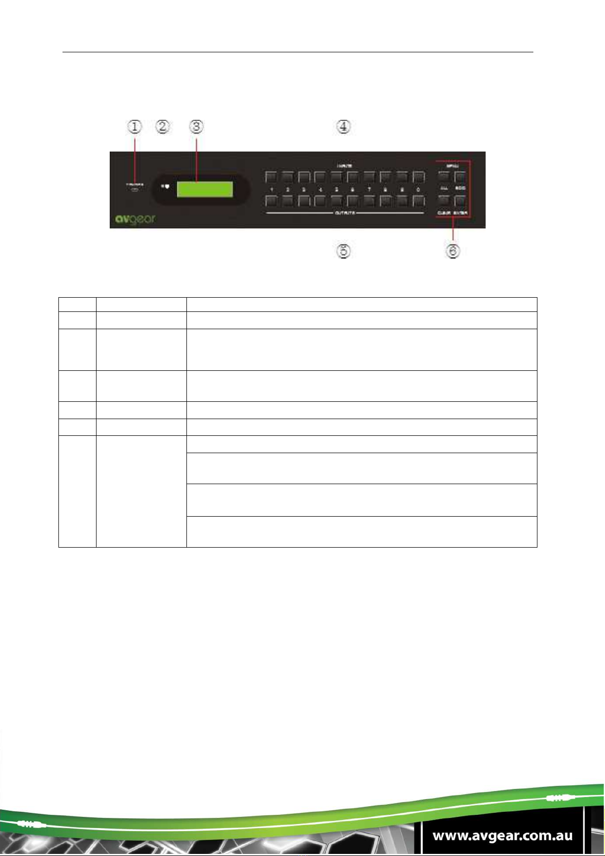
3.1. Front Panel
No.
Name
Description
①
FIRMWARE Micro USB port, used for firmware updates
②
Power
indicator
Illuminates
green once powered on
Illuminates red in standby mode
Turns off when powered off
③
System
Monitor
Displays real-time operation status
④
INPUTS Input selection buttons, ranges from 0~ 9
⑤
OUTPUTS Output selection buttons, ranges from 0~ 9
⑥MENU
ALL: Select all inputs/ outputs
EDID: EDID management button, enable input port to learn the
EDID data from output devices.
CLEAR:
: :
: Withdraw an operation before it comes into effect/
exit query mode
ENTER: confirm operation/ long-press (3s or more) to enter
query mode
Note:
1. Input/output channels are recognized as double-digit, so press channel 1~9 as
01~09, the interval should not exceed 8s.
2. Operations will be automatically canceled 8s later unless ENTER is pressed to
confirm.
AVG-FMM12
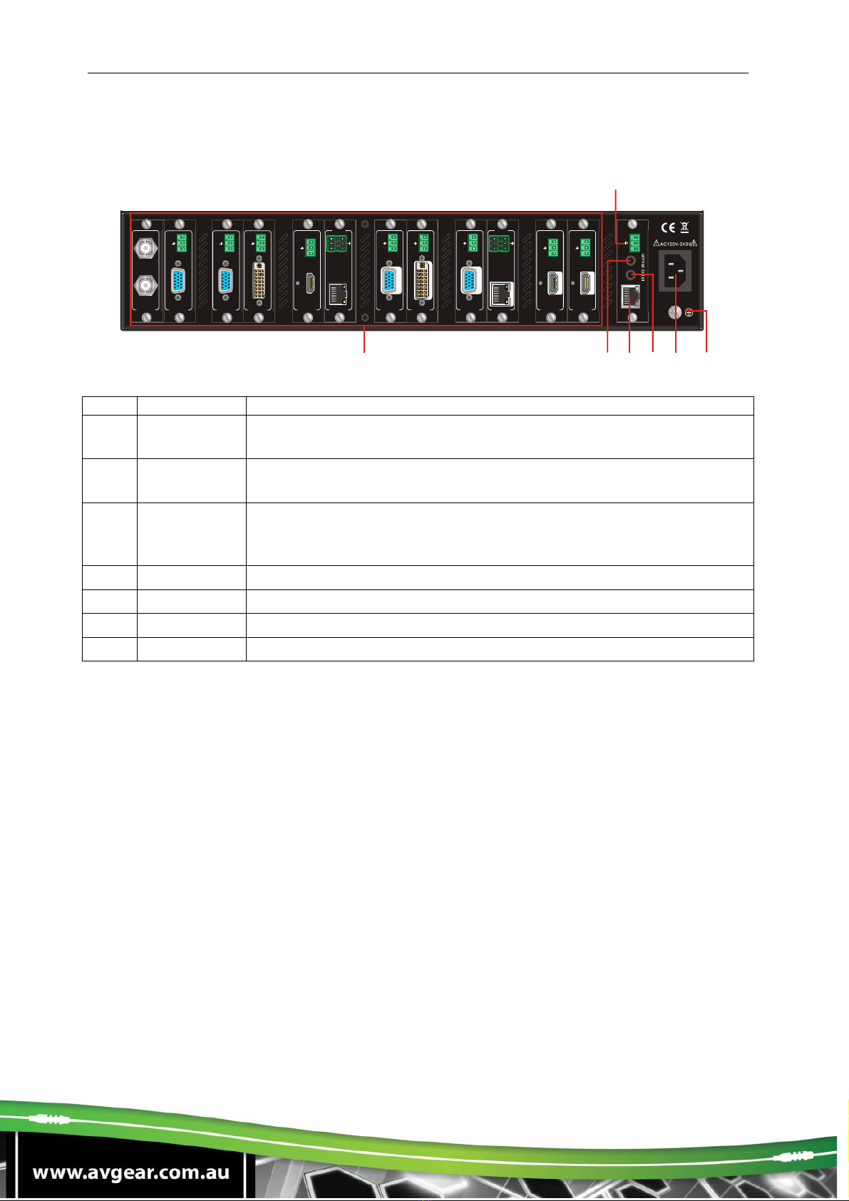
3.2. Rear Panel
No. Name
Description
①
Card Slots Flexible card slots, 12 in total, insert input/output signal cards
here
②
RS232 Serial control port, connect with RS232 port of control device,
control the device or 3
rd
party device connected to I-TP & O-TP
③
IR ALL IN
Input port for IR control signal, connect with IR receiver (5V, with
carrier), works with IR emitters connected to IR OUT of far-end
HDBT receivers
④
TCP/IP TCP/IP control port, connect with control device (e.g. a PC)
⑤
IR EYE Connect with IR receiver (5V, with carrier) to control the switcher
⑥
Power port Connect with 100~240V AC outlet
⑦
Ground Connect to ground
Notes:
1. AVG-FMM12 supports flexible card configurations to form 11x1~1x11 matrix
options.
2. Pictures shown in this manual are only for reference.
INP UT
SDI
LOOP
1
2
3
4
5
7
12
11
R
S
2
3
2
T
x
R
x
T
C
P
/
I
P
①
②
③
④
⑤
⑥
⑦
VG A
IN PU T
AU DIO
L
R
D
V
I
INP UT
AU DIO
L
R
T
x
R
x
L
R
RS23 2 AU DIO
HDBaseT
INP UT
Sea mle ss
H
D
M
I
IN PU T
A
U
D
I
O
L
R
D
V
I
OUT PUT
AUDIO
L
R
V
G
A
OUT PUT
AU DIO
L
R
T
x
R
x
L
R
RS2 32
AUDI O
HDBaseT
OU TPUT
Sea mle ss
8 9 10
H
D
M
I
OUT PUT
A
U
D
I
O
L
R
V
G
A
OU TPUT
AU DIO
L
R
H
D
M
I
OU TPUT
A
U
D
I
O
L
R
VG A
INP UT
AU DIO
L R
AVG-FMM12
3.3. Signal Cards
The AVG-FMM12 boasts 12 card slots for flexible input & output signal card
combinations, various signal cards can be selected, including VGA, DVI, SDI, HDBT
and HDMI according to design requirements. All the signal cards support seamless
distribution and are hot-pluggable.
The chart below shows all the signal cards the AVG-FMM12 frame supports:
Input
Output
Card
Ports
Card
Ports
I-TP HDBT & Analog Audio
with RS232 O-TP HDBT & Analog Audio with RS232
I-SD SDI & Loop output
I-VG VGA & Analog audio O-VG VGA & Analog audio
I-DV DVI & Analog Audio O-DV DVI & Analog Audio
I-HD HDMI & Analog Audio O-HD HDMI & Analog Audio
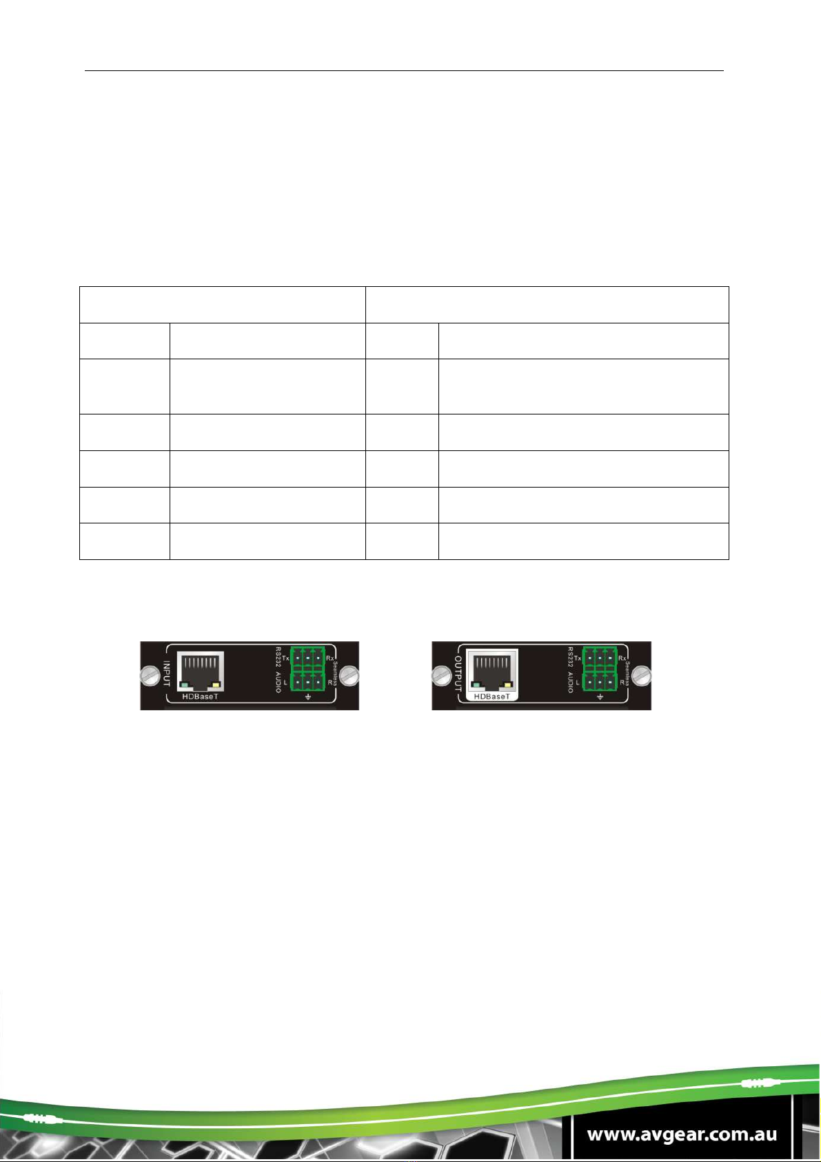
3.3.1. I-TP& O-TP
Figure 2- 1 I-TP
Figure 2- 2 O-TP
HDBT signal card
HDMI 1.3 & HDCP 1.3 compliant
Works with a HDBT transmitter/receiver to achieve long-distance (up to 70m via
HDBT certified CAT6 cable) transmission for a 1080p signal and bi-directional
RS232 control
Real-time working status indicator: green LED blinks once when powered on,
yellow LED illuminates when the port is connected with HDBT devices
HDBT port supports PoE
AVG-FMM12
Comprehensive audio capacity with embedded HDMI audio and 1 auxiliary
analog audio port, audio source selectable via RS232 command/GUI
Output resolution adjustable via command or GUI
Supports EDID management and DDC communication
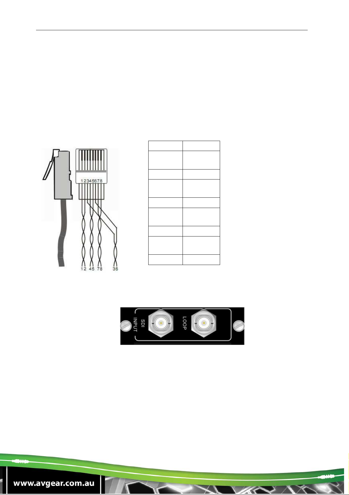
Pin layout of the HDBT connector:
3.3.2. I-SD
Single SDI input card
1 SDI input transmits high-definition 3G-SDI/HD-SDI/SDI signal
Resolution range: 1080p, 1080i, 720p
Loop transmits 1080p signal up to 100m
1 loop output for local monitoring
Pin
C
olor
1 orange
white
2 orange
3 green
white
4 blue
5 blue
white
6 green
7 brown
white
8 brown

AVG-FMM12
The BNC connector is shown as the figure below.
Sleeve ( )
Tip (+)
BNC Connector
3.3.3. I-VG & O-VG
Figure 2- 3 I-VG
Figure 2- 4 O-VG
Single VGA signal card
VGA port supports VGA, C-Video & YPbPr
Input card automatically recognizes input signal format
Output signal format adjustable via commands or GUI
Output resolution adjustable via commands or GUI:
Resolution range for VGA signal: 800x600, 1024x768, 720p, 1280x1024,
1080i, 1080p (default), 1920x1200
Resolution range for YPbPr signal: 720p, 1080i, 1080p
Resolution range for CVBS signal: 480i, 576i
AVG-FMM12
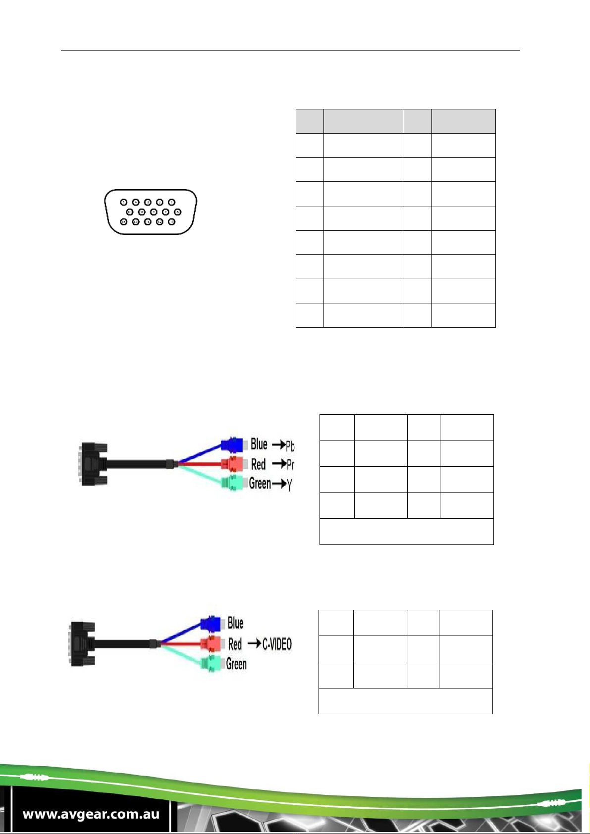
Pin layout of the VGA connectors (female):
Pin
Signal
Pin
Signal
1
RED
9
KEY/PWR
2
GREEN
10
GND
3
BLUE
11
ID0/RES
4
ID2/RES
12
ID1/SDA
5
GND
13
HSync
6
RED_RTN
14
VSync
7
GREEN_RTN
15
ID3/SCL
8
BLUE_RTN
When connecting to an YPbPr or CVBS signal, insert converting cables according to
specific pin definitions (see the figures below):
VGA- YPbPr:
VGA- CVBS:
Pin
Signal
Pin
Signal
1 RED 6 GND
2 GREEN
7 GND
3 BLUE 8 GND
Other pins are not used.
Pin
Signal
Pin
Signal
1 RED 6 GND
7 GND 8 GND
Other pins are not used.

AVG-FMM12
3.3.4. I-DV & O-DV
5
I
-
DV
O
-
DV
Single DVI signal card
HDMI 1.3 & HDCP 1.3 compliant, able to transmit DVI/HDMI signals
Output resolution adjustable via commands or GUI: including auto, 800x600,
1024x768, 720p, 1280x1024, 1080i, 1080p (default), 1920x1200
Input/Output audio can be enabled/disabled via commands (default settings:
input audio: disabled, output audio: enabled)
Features EDID management and DDC communication.
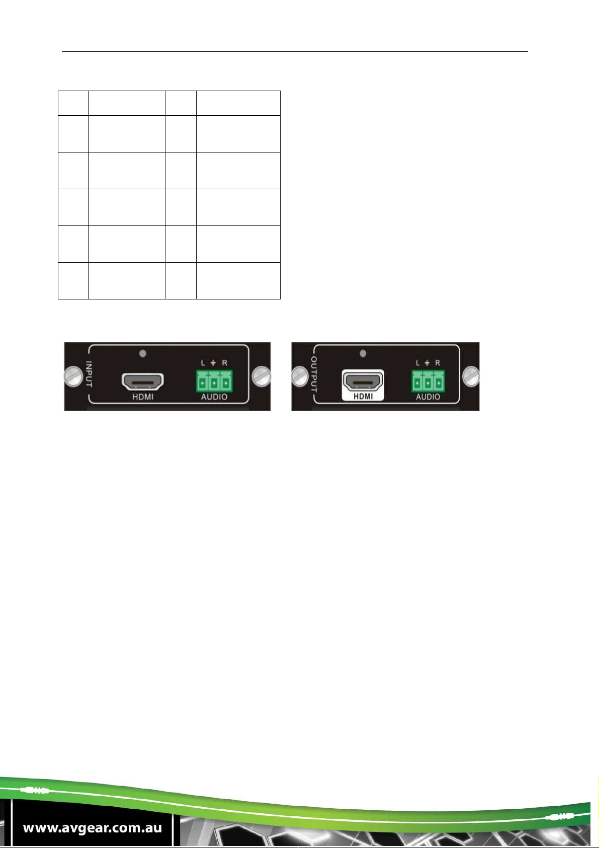
Pin Layout of the DVI-I connector (Dual-Link). (Female):
Pin
Function
Pin
Function
1
T.M.D.S.Dat
a2-
13
T.M.D.S.Data
3+
2
T.M.D.S
.Dat
a2+
14
+5V Power
3
T.M.D.S.
Data 2/4
Shield
15
Ground (return
for +5V,
Hsync and
Vsync)
4
T.M.D.S.
Data 4-
16
Hot Plug
Detect
5
T.M.D.S.
Data 4+
17
T.M.D.S. Data
0-
6
DDC Clock
18
T.M.D.S. Data
0+
7
DDC Data
19
T.M.D.S. Data
AVG-FMM12
0/5 Shield
8
Analog
Vertical Sync
20
T.M.D.S.Data
5-
9
T.M.D.S.Dat
a1-
21
T.M.D.S.Data
5+
10
T.M.D.S.Dat
a1+
22
T.M.D.S.
Clock Shield
11
T.M.D.S.Dat
a1/3 Shield
23
T.M.D. S.
Clock +
12
T.M.D.S.Dat
a3-
13
T.M.D.S.Data
3+
3.3.5. I-HD & O-HD
I
-
DV
O
-
DV
Single HDMI signal card
HDMI 1.3 & HDCP 1.3 compliant, able to transmit DVI/ HDMI signals
Auto-detects input resolution
Max resolution: 1080p@60Hz
Output resolution adjustable via commands or GUI: including auto, 800x600,
1024x768, 720p, 1280x1024, 1080i, 1080p (default), 1920x1200
Supports EDID Management and DDC communication
Input audio source selectable via command, including HDMI embedded audio
(default), and analog audio
Analog output audio can be enabled/disabled via commands (default: enabled)
Supports EDID management & DDC communication
AVG-FMM12
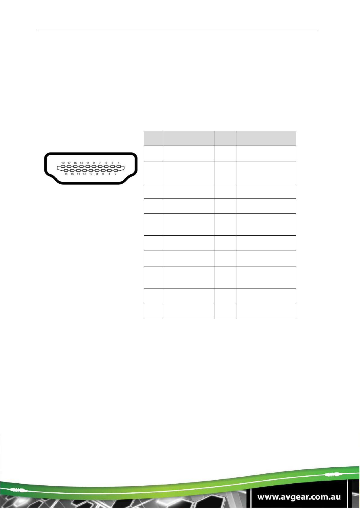
Pin layout of the HDMI connector (female):
No.
Signal
No.
Signal
1
TMDS Data 2+
11
TMDS Clock
Shield
2
TMDS Data 2
Shield 12
TMDS Clock-
3
TMDS Data 2
-
13
CEC
4
TMDS Data 1+
14
N.C.
5
TMDS Data 1
Shield 15
SCL
6
TM
DS Data 1
-
16
SDA
7
TMDS Data 0+
17
DDC/CEC
Ground
8
TMDS Data 0
Shield 18
+5V Power
9
TMDS Data 0
-
19
Hot Plug Detect
10
TMDS Clock+
TMDS Clock
Shield
AVG-FMM12
4. System Connection
4.1. System Applications
Industrial build quality combined with reliable performance for control and signal
transmission makes the AVG-FMM12 ideal for use in the custom installation industry,
IT computer space, signal monitoring, big screen displays, conference systems,
television broadcast, education, banking and security institutions etc.
4.2. Usage Precautions
1. The system should be installed in a clean environment with temperature and
humidity maintained to within equipment specification.
2. All of the power switches, plugs, sockets and power cords should be insulated and
safe.
3. All devices should be connected before power is turned on.
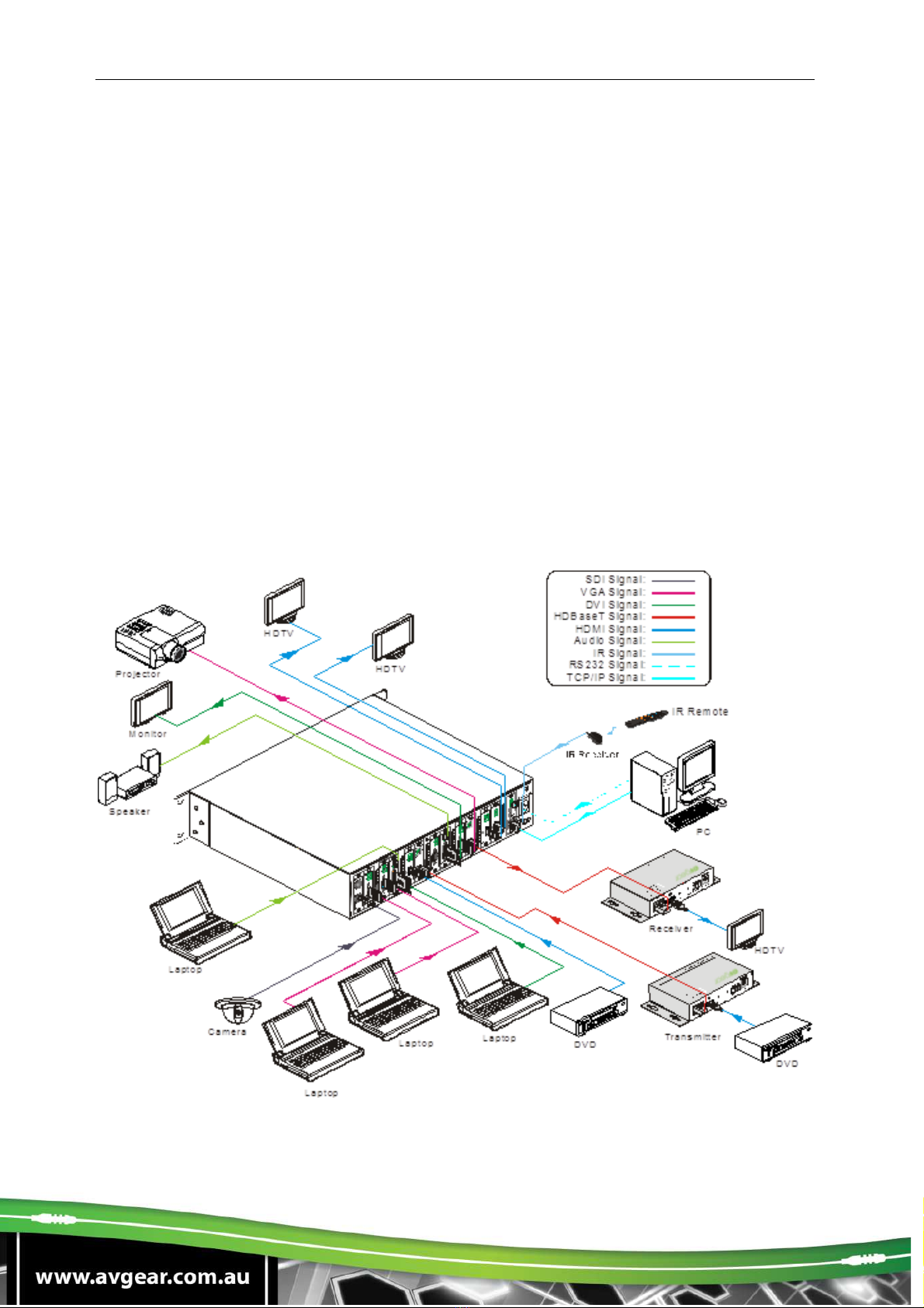
4.3. Connection Diagram

AVG-FMM12
4.4. Connection Procedure
Step 1. Insert necessary signal cards into the card slots
Step 2. Connect source device(s) (e.g. Blu-ray DVD) to corresponding input ports.
Step 3. Connect displays to corresponding output ports.
Step 4. Connect amplifier/speakers to audio output ports.
Step 5. Connect an IR Receiver to the IR EYE port to enable IR control.
Step 6. Connect a control device (e.g. a PC) to the RS232 port to enable serial
control.
Step 7. Connect a control device (e.g. a PC) to the TCP/IP port to enable TCP/IP
control.
Step 8. Insert a 100~240V AC outlet via the included power cord.

AVG-FMM12
5. System Operation
5.1. Front Panel Button Control
The AVG-FMM12 provides convenient front panel button control for I/O switching,
EDID management, and system query. Here is a brief introduction to the operations.
5.1.1. Switching I/O connection
Input/output channels are recognized as double-digits, press 01~09 for channel 1~9.
1. To switch one input to an output:
Operation: “INPUT”+“OUTPUT”+“ENTER”
Example: Switch input 01 to output 12:
+ +
2. To switch an input to several outputs:
Operation: “INPUT” + “OUTPUT” + “OUTPUT” +… + “ENTER”
Example: Switch input 2 to output 2 and 4
+ +
3. To switch an input to all outputs:
Operation: “input” + “ALL” + “ENTER”
Example: Switch input 02 to all outputs
+ +
Note: Indicators of the pressed buttons will blink green for three times if the switch is
done, then it will turn off. If the switch failed, they will turn off immediately.

AVG-FMM12
5.1.2. EDID Management
The AVG-FMM12 features EDID management to maintain compatibility between all
devices.
EDID Learning (from output):
One input port learns the EDID data of one output port
Operation: “EDID”+“INPUT”+“OUTPUT”+“ENTER”.
Example: Input 02 learns EDID data from output 4
+ + +
All input ports learn EDID data from one output port
Operation: “EDID”+“ALL”+“OUTPUT”+“ENTER”
Example: All input ports learn EDID data from output 04
+ + +
5.1.3. Query
Press and hold the button “ENTER” for 3 seconds to enter system query mode. The
chart below shows the information that can be obtained:
Function Items
Description
Example
Check customer serial
Interface shown after entering
query mode, customer serial
can be changed via RS232
command.
Check output resolution In query mode, press output
channel to check its resolution
Correspondence
between inputs and
outputs
“OUTPUT” + “ENTER”
Table of contents
Other AVGear Recording Equipment manuals


Popular Recording Equipment manuals by other brands


Contemporary Research
Contemporary Research IR-232 product manual

Mutable Instruments
Mutable Instruments GRIDS user manual

Alarm Lock
Alarm Lock AL-PCI2 installation instructions

AMX
AMX TPI-PRO-DVI-2 installation guide

Philips
Philips VoiceTracer DVT7500 quick start guide

Aritech
Aritech ATS1201 quick start guide


