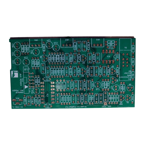
ER-808 – Assembly Guide
_____________________________________________________________________________________
_____________________________________________________________________________________
Page 2 of 5
Resistors
Arrange the resistors by value on the workbench in the same order as listed in the BOM and install each
numbered part for that value before moving onto the next.
Install the resistors on the TOP of the board. Take care not to mix up resistors which have similar color
codes.
Solder and clip the leads.
IC Sockets
Install the sockets on the TOP of the board. Observe the notch or mark on the sockets and align with
the notch or mark on the board. Solder.
Bus header
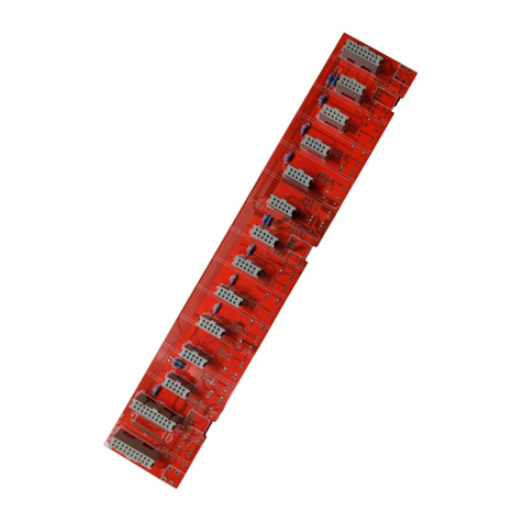
Install the 16 pin right angle bus socket on the BOTTOM of the board. This must be installed with the
correct orientation or the module will be damaged when the power is connected.
The cut-out in the socket should face the words "BUS HEADER", as shown in the photo.
The header must be completely flat and aligned with the PCB so clean up any joints that interfere with
this.
Ceramic and film capacitors
Install the capacitors on the TOP of the board. Solder and clip the leads.
Trimmer resistors
Install on TOP so the adjustment is accessible from the back edge.
Electrolytic capacitors
Install on the TOP. Make sure you orient correctly. The longer lead and/or the lead marked with a +
needs to be inserted into the hole that has the “+” marking near it. Leads marked with “-“ go in the
board hole WITHOUT the “+”. Solder and clip the leads.
Potentiometers, jack sockets
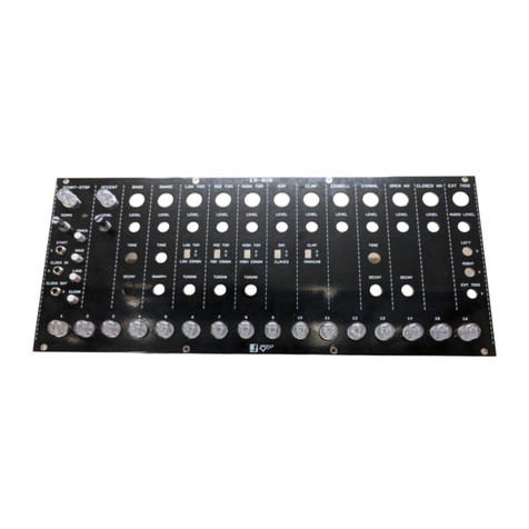
If the pots have positioning lugs on the front, cut these off with a sharp pair of flush cutting pliers.
Please ensure they are on the CORRECT SIDE OF THE BOARD before soldering otherwise PCB tracks and
pads may be damaged if they are desoldered. See Photo.
