JBL Synthesis SDP-25 User manual

SDP-25
SURROUND SOUND PROCESSOR

-2-
JBL SYNTHESIS SDP-25
TABLE OF CONTENTS
Introduction & Features................................................... 2
Installation & Setup......................................................... 2
Front Panel Controls & Indicators .................................... 3
Rear Panel Connections ................................................. 4
Remote Control .............................................................. 6
Input Connections .......................................................... 7
Output Connections ....................................................... 7
System Connections....................................................... 8
Setup & Configuration..................................................... 8
Operation..................................................................... 12
Zone 2 Operation ......................................................... 13
Troubleshooting Guide.................................................. 14
Specifications............................................................... 14
INTRODUCTION
Thank you for purchasing a JBL Synthesis SDP-25 Surround Sound Processor. You now have
at your command a unique product that has been designed to deliver the best possible sonic
performance regardless of the content being played, whether it is the latest blockbuster movie, a
major sporting event or your favorite music.
This Quick Start Guide is designed to give you the basic information needed to connect your
SDP-25 to the other components in your home theater system as well as to provide the basics
of setup and operation. For complete information on all that the SDP-25 has to offer please
download the full Owner’s Manual from the Support pages at www.jblsynthesis.com. Additional
support information may also be found in the Support Section of the JBL Synthesis web site.
Your dealer or installer is also a valuable resource and they may be able to assist you with
product questions. Of course, you may always contact JBL Synthesis Customer Service at
1-818-691-4171.
Welcome to the Synthesis family, we wish you many years of listening pleasure!
FEATURES
• Full suite of home theater audio formats
• Extensive connectivity options for up to twelve fully programmable audio/video sources
–Six HDMI inputs, including one on the front panel
–Two HDMI outputs, including one with ARC capability
–Composite and component video inputs for use with legacy video sources
–Five each optical and coaxial digital audio inputs and two each outputs
–7.1 Direct audio inputs
–USB Audio input for connection to digital music servers
• Flexible control options including full-featured remote control, RS-232 and IR blaster
connections
• Software upgradeable via USB connection
• Rack ears included for custom mounting applications
INSTALLATION AND SETUP
INSTALLATION CONSIDERATIONS
To ensure optimal performance, please pay attention to the instructions in this Quick Start Guide.
• Install the SDP-25 on a solid, flat, level surface that is dry, well-ventilated and out of direct
sunlight.
• Do not place the SDP-25 directly on a carpeted surface or cover any of the ventilation holes.
• Do not install the SDP-25 on a surface that is unstable or unable to support all four feet.
• Do not install it directly above another product, and do not put another product directly on
top of the SDP-25.
• Do not expose the SDP-25 to high temperatures or humidity, steam, smoke or excessive
dampness or dust.
WHAT’S IN THE BOX
Your new SDP-25 should include the following items. If anything is missing please contact your
dealer or installer before contacting JBL Synthesis as they may have used it to install you new
product:
• AC Power Cord
• Remote Control
• Batteries for the Remote Control
• Right and Left “rack ears”
• Mounting screws for the rack ears and the cover screw for the remote are packing in a small
poly bag
• This Quick Start Guide

-3-
JBL SYNTHESIS SDP-25 Front Panel Controls and Indicators
Standby/On Indicator: This LED indicator will light red when the AC mains power is applied and
the rear panel Master Power Switch is turned on. It will turn blue when the unit is turned on from the
front panel Standby/On Switch, the remote control or an external control system.
Standby/On Switch: Press this switch to turn the unit on or place it in the Standby/”Off” mode.
Input Indicators: When an input is selected by pressing a Source Selector button on the front
panel or remote, the LED above it will turn blue to confirm the choice.
Source Selectors: Press these buttons to choose the audio/video input played through the
main room system.
• The eight Source Selector buttons on the left side of the panel select from the HDMI and
analog sources connected to the rear panel jacks.
• The TV Source Selector plays the audio from a TV with Audio Return Channel capability
(ARC) connected to the HDMI 1/ARC output. There is no video associated with this source.
• The USB Source Selector plays the audio from a computer or other compatible device
connected to the rear panel USB Audio jack.
• The Front Inputs Source Selector toggles between the devices connected to the front
panel inputs.
Front HDMI Input: Connect the HDMI output of a source device to this jack for playback and
select it by pressing the Front Panel Input Button.
Front Audio Input: Connect an audio source to this jack for playback and select it by pressing
the Front PInput Button.
Information Display: This two-line LED display provides status information about your SDP-25.
The top line typically shows the input and the bottom line shows the current surround mode and
volume. When inputs are changed or the menus are in use the information shown will vary.
Infrared Sensor: The sensor behind this window received IR commands from the Remote Control.
Audio Selector: Press this button to choose between the Primary Digital, Secondary Digital or
Analog audio source in use.
Stereo Mode: Press this button to select one of these stereo playback modes:
• Stereo 2.1 plays two-channel audio with bass information going to the subwoofer
• Stereo 2.0 sends a full range audio signal to the left and right speakers and no audio to the
subwoofer
• Party Mode plays stereo sound through all speakers except the Center Channel.
• Stereo Direct sends a two-channel analog audio input directly to the volume control and
outputs without any signal processing or bass management.
Surround Mode: Press this button to toggle through the available surround modes
Zone 2 Video: When the Zone 2 Video option in the Zone 2 Setup Menu is set to "Enable",
pressing this button selects the video source for the second zone. Note that when the Zone 2
Video is active the HDMI Preview feature is not available. See page 13 for more information on
the Zone 2 system.
Zone 2 Audio: Press this button to select the audio input for the second zone. Note that the
audio format cannot be transcoded from one format to another. For example analog sources
may only be output via the analog outputs, optical digital via optical outputs, etc. See page 13
for more information.
Volume Control: Turn this knob to raise or lower the system output level.
FRONT PANEL CONTROLS AND INDICATORS
STANDBY
SDP-25 Surround Processor
Blu-ray SAT/ CBL Game Media DVR Video 1Video 2Video 3TV USB Front Inputs
HDMIFRONT AUDIO
Audio
Input
Stereo
Modes
Surround
Modes
Zone 2
Video
Zone 2
Audio
VOLUME
Standby/On
Indicator
Standby/On
Switch
Source Selectors Source
Indicators
Information Display Infrared
Sensor
Audio
Selector
Stereo
Mode
Zone 2
Video
Surround
Mode
Zone 2
Audio
Source
Selectors
Front HDMI Input
Front Audio Input
Volume
Conrol

-4-
JBL SYNTHESIS SDP-25 Rear Panel Connections
HDMI Inputs: Connect the output of an HDMI source device to these jacks.
HDMI Outputs: Connect these jacks to the input of your video display based on the selections
made for Zone 2 Video in the Zone 2 Setup Menu (See Page 13):
• The HDMI 1 jack will always carry the selected input source and the menus when they
are in use.
• When the Zone 2 is set to the factory default of "Disable" it will carry the selected input with
no menu overlays.
• When the Zone 2 Video Setting is changed to "Enable", the HDMI 2 jack will output the
source selected for the Zone 2 system.
• When you will be using the Audio Return Channel (ARC) to feed audio from a source in the
TV or display, such as a streaming service, connect the output marked ARC on the TV to
the HDMI 1/ARC jack.
USB Audio Input: Connect this port to a USB jack on a computer, media server or other device
that will be feeding digital audio to the SDP-25. A driver may be required to play audio from your
computer via this Input. For more information please see the SDP-25 Support section of
www.jblsynthesis.com.
Serial Control Port: When using a serial control system connect this jack to the controller. We
recommend that this port only be used by installers knowledgeable in programming RS-232
control systems.
Front IR Control: When this switch is set to the default position of On (up) the Front Panel IR
Sensor will capture commands from the Remote Control. When you are using external remote
command receivers you may want to set the switch to Off (down) to avoid interference.
Coax Digital Audio Inputs: Connect the coaxial digital audio output of a source device to
these jacks.
Coax Digital Audio Outputs: Connect these jacks to the coaxial digital input of a digital audio
recorder to record a selected digital audio source.
Optical Digital Audio Outputs: Connect these jacks to the optical digital input of a digital
audio recorder to record a selected digital audio source.
Optical Digital Audio Inputs: Connect the optical digital audio output of a source device to
these jacks.
Trigger Outputs: These jacks provide a 12 volt DC signal to control the on/off status of
connected devices with external trigger control.
• Trigger Output A will send a signal whenever the SDP-25 is turned on. We recommend that
this jack be used for connection to audio power amplifiers
• Trigger Output B sends a signal to control external devices such as screens and blinds
when the Trigger B setting for any input in the Input Setup Menu is changed to On for any
input. See page 9 for more information on Trigger programming.
REAR PANEL CONNECTIONS
Master Power
Switch
AC Power
Cord Socket
IR
Flasher
Input
USB
Upgrade
Port
Preamp
Outputs
Analog
Audio
Outputs
7.1 Direct
Inputs
Analog
Audio
Inputs
Composite
Video
Inputs
Component
Video
Inputs
HDMI
Inputs
Optical Digital
Audio Outputs
HDMI
Outputs
USB Audio
Input
Trigger
Outputs
IR Flasher
Output
Serial
Control
Port Front IR Control
IR Receiver Input
Optical Digital
Audio Inputs
Coax Digital
Audio Outputs
Coax Digital
Audio Inputs

-5-
JBL SYNTHESIS SDP-25 Rear Panel Connections
IR Flasher Input: Connect the output of a modulated IR signal from a simple IR receiver to this
input to use that receiver as the remote sensor.
IR Flasher Outputs: Connect an optional, external, IR blaster to this jack to repeat IR signals
received by the SDP-25 to other devices.
IR Receiver Input: Connect the output of a de-modulated IR signal from an IR system controller
to this input to use that receiver as the remote sensor.
Master Power Switch: Turn this switch to the On position to operate the product. When it
is in the Off position the SDP-25 is disconnected from AC power and will not respond to any
controls. In normal operation this switch may be left On, but it should be turned Off when the
unit will not be used for an extended period of time such as a vacation.
Component Video Inputs: Connect the component video (Y/Pr/Pb) outputs of a source device
to these jacks.
Composite Video Inputs: Connect the composite video outputs of a source device to these
jacks.
Analog Audio Inputs: Connect the analog two-channel outputs of a source device to these
jacks.
7.1 Direct Inputs: Connect the analog 7.1 outputs of a source device such as a Bluray or DVD
player to these jacks. The “LF” and “LR” inputs may also be used as an additional two-channel
audio input.
Analog Audio Outputs: Connect these jacks to the input of a recorder or multiroom system to
play or record a selected analog audio source. Note that digital audio inputs will not be sent out
through these jacks:
• Output 1, will output an analog source playing through the main system.
• Output 2, will output the source selected for Zone 2 Audio.
Preamp Outputs: Connect these outputs to the inputs of your audio power amplifier and
subwoofer(s).
USB Upgrade Port: When a software update is available for the SDP-25 is available, follow the
instructions supplied with the download to install it through this USB port.
AC Power Cord Socket: Connect the AC power cord supplied with the unit to this socket, and
connect the power cord plug to an AC outlet.

-6-
JBL SYNTHESIS SDP-25 Remote Control
REMOTE CONTROL
Power Toggle: Press this button to turn the unit on or place it in the Standby Mode.
Power On: Press this button to turn the unit on.
Power Off: Press this button to place the unit in the Standby Mode.
Audio Input: Press this button to chose between the Primary Digital, Secondary Digital or
Analog audio source in use. See Page 7 for more information.
Stereo Modes: Press this button to select one of these stereo playback modes:
• Stereo 2.1 plays two-channel audio with bass information going to the subwoofer
• Stereo 2.0 sends a full range audio signal to the left and right speakers and no audio to the
subwoofer
• Party Mode plays stereo sound through all speakers except the Center
• Stereo Direct sends a two-channel analog audio input directly to the volume control and
outputs without any signal processing or bas management
Source Selectors: Press these buttons to choose the audio/video input played through the
main room system.
• The Source Selector buttons choose from the HDMI and analog sources connected to the
rear panel jacks.
• The TV Source Selector plays the audio from a TV with Audio Return Channel capability
(ARC) connected to the HDMI 1/ARC output. There is no video associated with this source.
• The USB Source Selector plays the audio from a computer or other compatible device
connected to the rear panel USB Audio jack.
OSD: Press this button to bring up the menus for system configuration and other adjustments.
Once the menus appear use the Navigation and Enter buttons to find and select the desired
menu items.
Mute: Press this button to momentarily silence the audio output. Audio may be restored by
pressing the Mute Button again, or by changing the Volume.
Navigation Buttons: Press these buttons to move up/down/left/right through menu items when
the OSD is on the screen.
Enter: Press this button to enter a setting into the system memory.
HDMI View: Press this button to view preview windows of the HDMI active inputs. When the
preview windows appear use the left/right Navigation Controls to highlight the source you want
to view and then press Enter to select it.
Back: When the OSD menus are on the screen, press this button to return to the previous menu
or setting.
Volume Control: Press this button up or down to raise or lower the system volume.
Zone 2 Video: When the Zone 2 Video option in the Zone 2 Setup Menu is set to "Enable",
pressing this button selects the video source for the second zone. Note that when the Zone 2
Video is active the HDMI Preview feature is not available. See page 13 for more information on
the Zone 2 system.
Zone 2 Audio: Press this button to select the audio input for the second zone. Note that the
audio format cannot be transcoded from one format to another. For example analog sources
may only be output via the analog outputs, optical digital via optical outputs, etc. See page 13
for more information.
Surround Mode Buttons: Press or toggle one of these buttons to select a surround or
processing mode other than the default setting set in the menus or activated by the digital data
stream.
Power On Audio Input
Stereo Modes
Source Selectors
HDMI View
Navigation Buttons
Back
Zone 2 Audio
Zone 2 Video
Surround Modes
Surround Modes
Power Toggle
Power Off
OSD
Enter
Mute
Volume Control

-7-
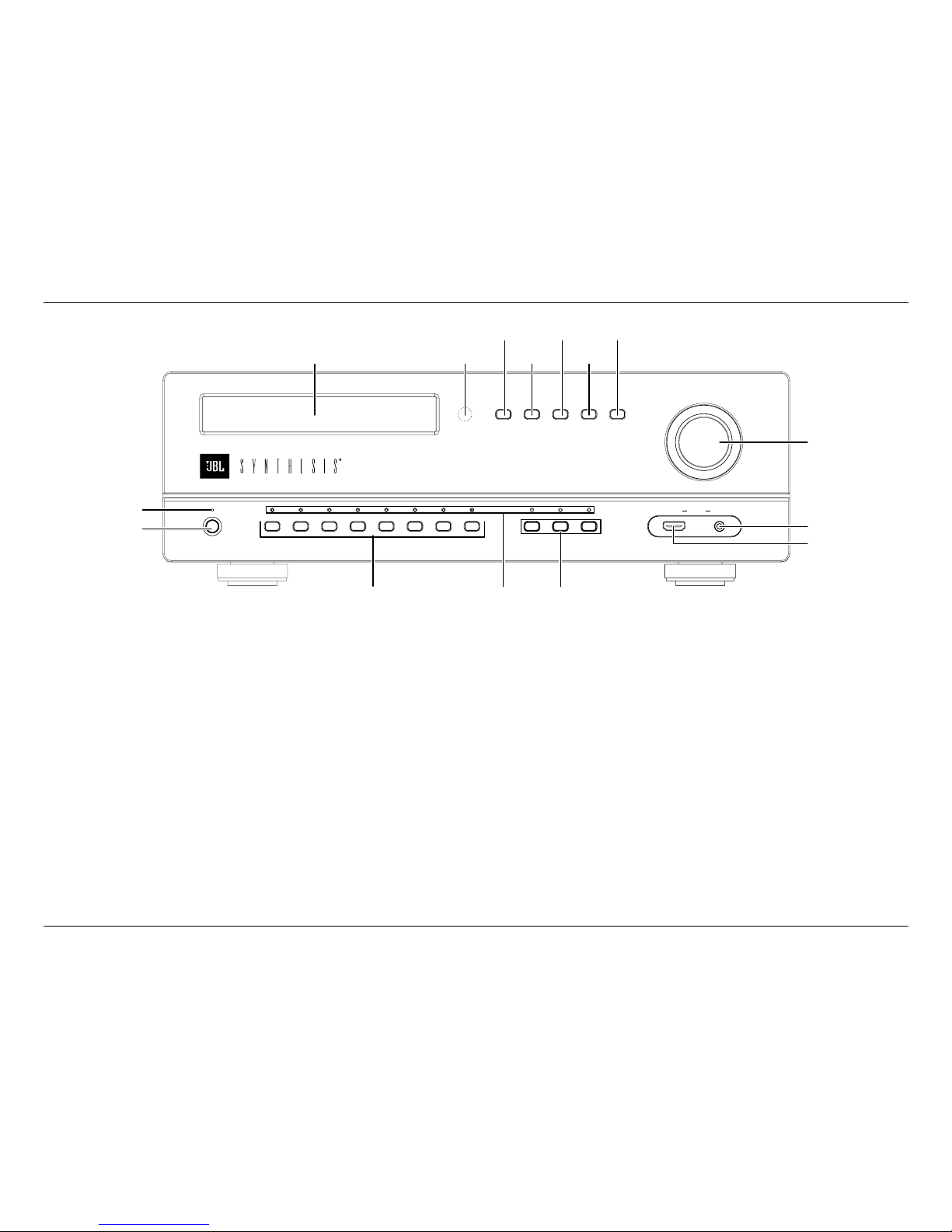
JBL SYNTHESIS SDP-25 Input and Output Connections
CONNECTIONS
SAFETY NOTE: When making connections between the SDP-25 and any other device be
certain that both the SDP-25 and other device are turned off and/or are disconnected
from AC power. To assure that there will be no unwanted signal transients that can
damage equipment or speakers, it is always best to unplug all equipment before
making any connections.
INPUT CONNECTIONS
The SDP-25 has 12 programmable sources that may be configured to suit your preferences.
When connecting devices you should make note of the default settings described here, and if
any of the connections differ you should adjust the Input Setup settings accordingly. See Page 9
for more information on Input Setup.
The SDP-25 allows a Secondary Audio source to be selected without changing the video or
audio input. This may be useful in situations where, for example, you are viewing the television
broadcast of a sporting event but wish to listen to the audio from radio commentary via an
external tuner or streaming content device. In that case, connect the digital or analog audio
output of the second device according to the chart below.
The chart below shows the default settings that match a source device to the recommended
jack. While you may connect any source to any compatible input, using this connection plan will
mean that the Input selection buttons on the remote and front panel will map to the right device.
For example, connect your Blu-ray player to HDMI 1, your cable or satellite set top to HDMI 2,
etc. Analog video connections should be made as shown.
SOURCE
NAME PRIMARY SECONDARY
Video Input Audio Input Digital
Audio Input
Analog
Audio Input
Blu-ray HDMI 1 HDMI 1 Coax 1 Audio 1
SAT/CBL HDMI 2 HDMI 2 Coax 2 Audio 2
GAME HDMI 3 HDMI 3 Coax 3 Audio 3
MEDIA HDMI 4 HDMI 4 Coax 4 Audio 4
DVR HDMI 5 HDMI 5 Coax 5 Audio 5
Video 1 Component 1 Optical 1 None 7.1 Direct
Video 2 Composite 1 Optical 2 None None
Video 3 Composite 2 Optical 3 None None
TV None ARC (HDMI 2
Output)
Optical 4 None
USB Component 2 USB None None
Front HDMI Front HDMI Front HDMI Optical 5 None
Front Audio Front HDMI Front Audio None None
• The “Audio Return Channel” (ARC) feature of HDMI allows digital audio to be passed back
from a TV set to the SDP-25 without the need for additional connections. This is particularly
useful to have the audio from streaming services accessed in a “Smart TV” sent to the SDP
for playback via your home theater system. To use this feature make certain that an HDMI
cable from the TV's HDMI/ARC jack is connected to the rear panel HDMI 1/ARC jack.
• To listen to audio from a music server or computer connect the source to the USB Audio
Input jack on the rear panel.
• When using a source such as a Blu-ray player that has 7.1 direct analog outputs, connect
them to the “7.1 Input” jacks on the rear panel and make certain that you adjust the
Input Setup Menu settings so that the correct video input is paired with the direct audio
connections.
If you anticipate using separate sources for the Main Room and the Zone 2 Audio outputs you
must make analog connections from a source even if there is also an HDMI or Digital connection.
Keep in mind that analog audio sources will only be output through the analog outputs just as
digital audio sources will only be output through the digital audio outputs. See Page 13 for more
information.
OUTPUT CONNECTIONS
NOTE: When there are two connections for any video or output, the connection labeled “1” is
for the Main Room, while connections labeled “2” are typically for the second zone although they
may also be used to feed a recorder.
BASIC CONNECTIONS
Since the SDP-25 has no built in amplifiers you will need to connect the audio Preamp Output
jacks to the inputs of your audio power amplifiers, which, in turn, will feed your speakers. We
recommend the following connection setup:
Front Left (LF) to Channel 1
Center (C) to Channel 3
Front Right (RF) to Channel 2
Left Surround (LS) to Channel 4
Right Surround (RS) to Channel 5
Left Back Surround (LB) to Channel 6
Right Back Surround (RB) to Channel 7
For amplifiers that have a trigger input, use the 3.5mm Trigger Cable supplied with the amplifier
to make a connection between Trigger Output A and the Trigger Input on the amplifier.
Depending on your system configuration and the design of your audio power amplifier an audio
signal may also be used to turn the amplifier on. Consult your amplifier’s Owner’s Manual for
more information.
Connect the HDMI1/ARC output to an input on your video display. If you are using the ARC
feature, make certain that the input on the TV is labeled “ARC”.
Connect the supplied power cord to the AC Power Cord Socket and then to an unswitched AC
wall output. Do not turn on the Master Power Switch until all connections are complete.

-8-
JBL SYNTHESIS SDP-25 Setup and Conguration / Main Menu
SYSTEM CONNECTIONS
If your SDP-25 is installed in a cabinet or in a way that the front panel IR sensor is not visible,
external IR sensors may be connections to the IR Flasher Input. Additional IR sensors and
repeaters may also be connected. Check the Front IR Control to make certain that it is in the On,
or “up” position unless an external sensor is in use.
Consult the complete Owner’s Manual for more information or ask your dealer/installer for
assistance with advanced system control including use of the Serial Control Port.
The Trigger connection for your amplifier should be made to the Trigger A jack as that supplies a
control signal whenever the SDP-25 is turned on.
The Trigger connection for any other product such as a screen or motorized blinds should be
made to the Trigger B jack. You must then change the Trigger B setting for any input where you
want this Trigger activated to On. See Page 9 for more information.
If your system includes a second zone, audio and video connections should be made to the
outputs labeled “2”.
SETUP AND CONFIGURATION
Place the supplied batteries in the remote by turning it over and removing the battery
compartment cover by slipping your fingernail under the latch and gently pulling the cover down
towards you. Place your fingernail under the tab and gently push it down and towards you to
remove the cover. Insert the two supplied AAA batteries being careful to follow the polarity
markings. Replace the cover by fitting the tabs at the bottom in first and then snapping the cover
into place. It is recommended that to hold the cover more securely, remove small Philips head
screw found in the bag with the rack mount ears and gently screw it in place. Do not over tighten.
Press the Master Power Switch on the rear panel to the left to place the SDP-25 in the Standby
mode and note that the Standby/On Indicator will light red. To turn the unit on press the Power
Toggle button on the remote or the front panel Standby/On Switch. The Power On button may
also be used. Note that the Standby/On Indicator will turn blue and the Information Display will
illuminate.
To enjoy the SDP-25 with maximum audio and video quality we recommend that you take the
time to make some initial adjustments. If your system has been installed by your dealer or a
custom installer check with them as they may have already made these adjustments and they
should be left as calibrated.
MAIN MENU
The SDP-25 is a highly flexible product that allows you to customize input settings, surround
modes, and adjust other system settings. To view and navigate through the menus, press the
OSD Button on the remote and then use the Navigation buttons to move the highlight to the
setting you want to adjust. Press the Enter button to go to the setting or press the Back button
to return to the previous menu screen. To clear the menus from the screen press the OSD
Button.
The Main Menu lists the top level menu choices as shown here.
Main Menu
Input Select
Input Setup
Speaker Setup
Zone 2 Select
General Setup
Exit
NOTE: The size of the menus and other on-screen messages will change when sources have
different video resolutions. This is a normal function of the SDP-25’s video system.

-9-
JBL SYNTHESIS SDP-25 General Setup / Input Setup
GENERAL SETUP
Before making initial setup adjustments you may wish to change some of the system settings
that will make it easier to configure your SDP-25. To do that, press the OSD button to call up the
Main Menu and then press the Down Navigation Button until General Setup is highlighted. Then,
press Enter to move to that menu.
General Setup
Language English
Front Brightness 75%
Volume Units dB
Volume Default On
Volume Level -30dB
Units of Measure Inch
RS232 Control Off
CEC Control Off
Menu Appearance
Transparency Mid
Status Message 3 Seconds
Menus 1 Minute
Global Lip Sync 0ms
Auto Power Down On
FW Version VX.xx/X.xx
Factory Settings
Complete information on the function and adjustments for the settings in this menu may be
found in the full Owner’s Manual, which may be downloaded from the Support section of the
JBL Synthesis web site a www.jblsynthesis.com. However, at this time there are three important
settings that you may wish to change.
• The Language setting may be changed to French, Spanish, Dutch, German, or Italian.
• You may display the Speaker Distances in centimeters, rather than inches, by changing the
Units of Measure setting.
• Changing the setting for “Menus” will keep the on-screen menus on the display for up to ten
minutes, making it easier to make initial setup adjustments.
• The adjustments made in the General Setup menu are applied to all inputs.
• The Factory Settings option is used to return all settings to their original factory defaults.
When these, or any other adjustments are complete press the Back button on the remote to
return to the Main Menu.
INPUT SETUP
If you have made any connections that are different from those shown in the factory menu
default settings chart on Page 7, press the down navigation button so that Input Setup is
highlighted and press Enter.
Input Setup
Source Blu-ray
Rename Blu-ray
Video Input HDMI 1
Audio Source HDMI 1
Secondary
Digital Audio Coax 1
Analog Audio Audio 1
Surround Mode PLII(x) Movie
Lip Sync 0ms
Audio Adjustment
Trigger B Off
Back
The settings in the Audio Adjustment sub-menu are best made when all other setup adjustments
are complete and a source is playing. See Page 12 for more information.
When configuring an Input note the following options:
• Connecting and configuring Secondary analog and/or digital inputs with a source allows
them to be used for the Zone 2 system since the output audio format must be the same as
the input. The SDP-25 does not convert one format to another.
• The Lip Sync setting made in the Input Setup menu is applied for that input source only and
is added to the Global Lip Sync entered in the General Setup Menu.
To turn or activate a voltage-controlled device such as a motorized screen or blinds when a
specific input is in use, change the setting for Trigger B to On.

-10 -
JBL SYNTHESIS SDP-25 Speaker Setup
SPEAKER SETUP
To assure the best audio performance we recommend the Speaker Settings must be adjusted to
match your system’s specific configuration. However, if your installer has already calibrated the
audio levels we strongly recommend that you use those settings without any changes.
Speaker Setup
Speaker Cong 7.1
Speaker Distance
Speaker Level
DTS – HD Remap 5
Factory Reset
Back
Note the following regarding the Speaker Setup options:
• The numbers shown for Speaker Configuration will change in accordance with the speakers
set as available in the menu below.
• The DTS-HD Remap options will vary according to the number of speakers in your system
and whether or not there are Height Speakers. Consult the complete Owner’s Manual for
more information on DTS-HD Speaker Remap.
• The Factory Reset option returns the Speaker Configuration settings only to their
factory defaults.
Speaker Conguration
Front L/R 80Hz
Center 80Hz
Side L/R 80Hz
Rear L/R 80Hz
Height L/R None
Subwoofer Yes
Back
The default crossover settings for Speaker configuration are in accordance with industry
standards. If your system has a different number of speakers or if Height speakers are used in
place of Surround Rear speakers, make the adjustments in this menu. If there are no speakers
at any position select “None” and that position will then be grayed out on other Speaker-related
menus.
The next critical setting is for the distance between the speakers and the primary listening
position. This is important to assure a seamless soundfield that has all audio arriving in
synchronization from one channel to the next.
Speaker Distance
Front Left 120 in
Center 120 in
Front Right 120 in
Side Left 120 in
Side Right 120 in
Rear Left 120 in
Rear Right 120 in
Height Left None
Height Right None
Subwoofer 120 in
Back

-11 -
JBL SYNTHESIS SDP-25 Speaker Level
The final critical adjustments are the speaker output levels.
Before making any Speaker Level adjustments, first set the volume to a comfortable listening
level using a movie or musical selection you are familiar with, then use the Auto setting to make
certain that the speakers are properly connected. To do that, first navigate the highlight so
that the Test Signal Options appear. Then press the down Navigation button so that Auto is
highlighted and press Enter.
Speaker Level
Test Signal Off
Front Left 0 dB
Center 0 dB
Front Right 0 dB
Side Left 0 dB
Side Right 0 dB
Rear Left 0 dB
Rear Right 0 dB
Height Left None
Height Right None
Subwoofer 0 dB
Back
It is essential that you adjust the level so that the output of each channel is identical as shown on
a sound pressure level meter or by using any of the “SPL Meter” apps available for smartphones
or tablets. When setting the levels make certain that the meter or app is set to display C-Weight/
Slow.
Speaker Level
Test Signal Test Signal
Front Left Off
Center Manual
Front Right Auto
Side Left
Side Right
Rear Left
Rear Right
Height Left
Height Right
Subwoofer
Back
The on-screen menu will return to showing the output level settings and a test noise will circulate
around the room. As the highlight moves from one speaker location name to another verify that
the test noise is coming from the speaker name shown. If all speakers are properly connected,
proceed to adjust the levels. If the test tone for any highlighted speaker location does not
match the speaker the test noise is coming from, turn off your SDP and amplifiers and change
the wiring so that the speakers are connected properly. When this is done turn the SDP and
amplifiers back on and repeat the Auto test cycle to make confirm that the connections are
made correctly.

-12 -
JBL SYNTHESIS SDP-25 Audio Adjustment / Operation
When all speaker positions have been verified you may adjust the levels in one of three ways:
• To have the test noise automatically circulate use the settings described above. As the test
noise moves from one speaker to another press the Enter button to stop the test noise at
any speaker and then use the Up or Down navigation buttons to raise or lower the output
level. When no adjustment is made for five seconds the test noise will resume circulation.
Repeat this process until the output SPL level is equal at all speakers. Press the Back
Button to return to the main Speaker Setup menu.
• To manually move the test noise from one speaker location to another, first highlight the
Test Signal line and then press the down Navigation button to highlight Manual and then
press Enter. Once the channel level adjustments return to the screen and the test noise is
heard you may then use the up or down Navigation Buttons to move the test noise from one
channel to another. To adjust the level for a channel press the Enter Button and note that the
highlight will move to the right. Press the Up or Down Navigation buttons to raise or lower
the output level and then press Enter to return to channel selection. When the output level is
equal at all speakers. Press the Back Button to return to the main Speaker Setup menu.
• To adjust the output levels using an external source such as a test disc or signal generator
first make certain that the input for that source has been selected before proceeding.
The Audio Adjustment menu is a sub-menu of the Input Setup menu described on Page 9.
The adjustments in this menu allow you to fine tune settings that are best made when an
audio source is playing so that you may immediately judge the impact of any setting changes.
Complete descriptions of these settings may be found in the Owners Manual that may be
downloaded from the Support section of www.jblsynthesis.com.
Audio Adjustment
Dolby Volume Off
Dolby Half Mode Off
Dolby DRC Off
Dolby PLII (x)
Panorama Off
Center Width 0
Dimension 0
Dolby / DTS
Sub Trim 0 dB
Bass Aug Off
Stereo + Sub
Sub Trim 0
Tone Controls
Treble 0 dB
Bass 0 dB
Back
There are a wide variety of other settings and system settings, including those on the General
Setup menu, but these are not generally required for initial installation. Download the full Owner’s
Manual from www.jblsynthesis.com to view the manual.
Once these initial settings have been made, your system is ready for normal operation with
additional fine tuning that may be done once you have a feel for the way the system sounds and
operates.
OPERATION
Before using the SPD-25, make sure that the Master Power Switch on the rear panel is turned
on. Turn the unit on by pressing the Power Toggle or Power On button on the remote or the
Standby/On switch on the front panel.
MAIN ZONE
To select an input, simply press the button on the remote or front panel corresponding the desired
source and adjust the volume using the remote or front panel control. To momentarily silence the audio
press the Mute button. Press it again or tap the Volume Control to restore normal listening.

-13 -
JBL SYNTHESIS SDP-25 Zone 2 Operation
The SDP-25 has a unique HDMI Preview feature that allows you to see all available HDMI
sources at once. Press the HDMI View Select button on the remote and five windows will appear
at the top of the screen. Press the left/right Navigation buttons and note that as you move
across the available sources one will drop down below the top row and the name of each input
will appear in the lower left corner of the screen. Press the Enter button to view that source in full
screen mode with audio.
The surround mode will automatically be selected to match the incoming data stream or as set
in the factory defaults for PCM or analog audio sources. You may change the surround mode
pressing the Surround Modes button on the remote or the Surround Mode Selectors on the front
panel.
Note that the availability of some modes or functions is dependent on the source being used.
Finally, surround mode selections, particularly those for two-channel/stereo sources are not
“sticky”. That means that they will be applied only during one listening session and the unit will
revert to the standard preset or default the next time that source is selected.
When you change the volume, input or surround mode a message box will briefly appear in the
lower right corner to confirm the selection. You may change the length of time this message
appears by changing the setting for Volume Status in the General Setup Menu.
ZONE 2 OPERATION
The SDP-25’s Zone Video system allows you for send a video source to a second room.
Depending on the settings it may be either the same source playing in the main room, or a
different source.
IMPORTANT NOTE: The Zone 2 system only operates when the SDP-25 is turned on for the
main room. If you wish to watch or listen in the second zone you must leave the SDP-25
turned on.
VIDEO
When the Zone 2 Video is set to Disable, which is the factory default, the Zone 2 Video buttons
do not function since the HDMI 2 Output is identical to that for the main room (without menus or
status messages) and may not be changed.
In order to view a different video source in the second zone some settings must be changed in
the Zone 2 Setup menu.
Zone 2 Setup
Video Control Disable
Video Source Blu-ray
Audio Source Blu-ray
Back
When the Zone 2 Setup menu is on your display, you must change the Video Control setting
to Enable. To do that, with Video Control highlighted, press the Enter button and then the
Navigation buttons so that Enable appears and then press Enter again.
• When the setting for Video Control is changed to Enable the Video Source setting will
change from being grayed out to being viewable. Press Enter to open the list of available
video sources, but note that only one analog video input may be used at a time; different
analog video sources may be selected for the Main Room and Zone 2.
• When the Video Control setting is set to Enable the HDMI View function is not available.
• To change the Video input to the Zone 2 system press the Zone 2 Video button on the front-
panel or remote control. Note that when an HDMI input is used for Zone 2 you may not pair
it with an analog audio source.
AUDIO
You may listen to a different audio source in the second zone form the one playing in the main
room provided that you have an amplifier or powered speakers connected to the Zone 2 Audio
Outputs.
The Audio source for the Zone 2 system may be changed in the Zone 2 Setup menu, but you
may find it easier to use the Zone 2 Audio button on front-panel or remote.
The SDP-25 cannot convert the format of an audio input source. Accordingly, analog audio will
be available only through the Analog 2 Audio Outputs and digital audio from the Coax Digital or
Optical Digital.
• To use a digital product such as a Blu-ray player, set-top box or streaming player as a
Zone 2 Audio source we recommend that you make an analog, as well as HDMI or digital
connection and create a separate virtual input as shown on Page 9. This allows the source
to serve as a digital source for the main room while also being used in the remote zone
when another digital video source is in use in the main room.
• The audio outputs for the Zone 2 system are at a fixed level. Accordingly, you must provide
some volume control at the remote room via the amplifier, AVR or other device used to play
the audio.

-14 -
JBL SYNTHESIS SDP-25 Troubleshooting Guide
TROUBLESHOOTING
Incorrect connections, configuration or operation is sometimes mistaken for product
malfunction. If problems occur, see this section for troubleshooting information. If a problem
persists, please contact your JBL Synthesis support or your authorized dealer or installer.
NO POWER • If the front panel indicators and front panel display do not
light, check to make certain that the AC power cord is firmly
inserted into the AC Power Socket and that the rear panel
Main Power Switch is turned on.
POWER ON, BUT NO AUDIO
FROM ANY SOURCE
• Make certain that both the audio and trigger connections to
the amplifier are solid.
• Make certain that the amplifier is turned on and operating
properly.
AUDIO FROM SOME, BUT
NOT ALL, CHANNELS
• Make certain that all audio input and output connections
solid.
• Check the settings in the Speaker Configuration sub-menu
in the Speaker Setup menu group. Be certain that there is a
frequency setting (e.g. 80Hz) next to each speaker used in
your system.
• Remember that sound does not always appear from all
speakers at all times, even in a multi-channel program.
NO OR LOW BASS OUTPUT • Make certain that the connections between the SDP-25 and
your subwoofer are on.
• If your subwoofer has “auto-turn on” circuitry, check the
settings.
• Check and adjust the levels on your subwoofer.
• Check the settings in the Speaker Configuration menus
•In the Speaker Setup sub-menu make certain that “Yes”
appears next to “Subwoofer”.
•In the Speaker Level sub-menu adjust the level setting
for Subwoofer as needed.
UNIT DOES NOT RESPOND
TO REMOTE CONTROL
• Check and replace batteries as needed
• Make certain front panel remote sensor is not obscured

-15 -
JBL SYNTHESIS SDP-25 Specications
SPECIFICATIONS
MAIN ZONE AUDIO
Frequency Response: 20 Hz – 20 kHz, ±0.25dB
Analog Input Impedance: 47K ohms
Input Level: 4 Vrms in DSP modes
4 Vrms in 2Ch Bypass Mode
Output Impedance: 480 Ohms
Digital Coax Signal Strength: 0.5V p-p
Output Level: 4 Vrms
Signal-to-Noise Ratio: 90dB in DSP Modes
98dB in 2ch Bypass Mode
THD + Noise: <0.007% in DSP Modes
<0.015% Analog in - Bypass & DSP Modes
1 kHz at 1.0VRMS
Bass Management:
High-Pass Filter:
Low-Pass Filter:
2nd order (x7)
4th Order, 40 - 200Hz Crossover Freq.
Audio Resolution: Up to 7.1 Channels at 192kHZ/24-bit
Supported Audio Formats: Dolby TrueHD, DTS-HD Master Audio, DVD Audio
Crosstalk: <72dB
A/D Conversion: 24-Bits, up to 192 KHz, Delta-Sigma
114dB DR, -100dB THD+N
D/A Conversion: 24-Bits, up to 192 KHz, Delta-Sigma
114dB DR, -100dB THD+N
DSP Engine: Dual TI TMS320D
Low Frequency Cutoff: < 10Hz (All speaker channels in Bypass Mode)
High Frequency Cutoff: >200Hz (All speakers in Bypass mode, -3dB point)
VIDEO INPUT & OUTPUT CONNECTIONS:
HDMI Inputs: 6 HDMI Type A (19 pin) connectors
HDMI Outputs: 1x HDMI Type A (19 pin) connection with
Audio Return Channel
1x HDMI Type A (19 pin) connection for Main/2nd Zone
HDMI Features: 12-bit Deep Color (1080p)
3D Pass-through
xvYCC (x.v. Color)
Video bandwidth up to 300 MHz
4K support to 2160, 50p/60p, 8-bit, 4:2:0
Composite (CVBS) Video Inputs: 2x @ 1.0V p-p, 75 ohms
Composite (CVBS) Video Outputs: 1x 1.0Vp-p, 75 ohms
Component Video Inputs:
Cb/Cr, Pb/Pr:
Y:
2x
0.75Vp-p, 75 ohms
1V p-p, 75 ohms
AUDIO INPUT & OUTPUT CONNECTIONS:
Analog Audio Inputs: 5x stereo single-ended/unbalanced L/R pairs
1 set 7.1 single-ended/unbalanced (L/C/R/LS/RS/LBS/
RBS/Sub)
1x 3.5mm stereo (Front Panel)
Analog Audio Outputs: 2x stereo single-ended/unbalanced L/R pairs
1 set 7.2 single-ended/unbalanced (L/C/R/LS/RS/LBS/
RBS/Sub 1/Sub2)
Digital Audio Inputs: 6x via HDMI
5x Coaxial (RCA) 75 ohms (S/P-DIF)
5x Optical Toslink (S/P-DIF)
1x USB 2.0 Type B
DATA AND CONTROL CONNECTIONS:
Trigger Outputs: 2x 12 VDC, 300mA, Trigger B programmable
USB: 1x USB Type A for software updates only
Data Connection: RS-232 via DB-9 connector for Control and System
Feedback
IR Inputs: Front Panel IR sensor, switch selectable for on/off
1x IR in, 1x Flasher In, 3.5mm jacks
IR Outputs: 3x, 3.5mm jacks
ELECTRICAL & PHYSICAL SPECIFICATIONS:
Mains Voltage: 120 VAC or 230 VAC [factory-set]
Power Consumption: Standby: < 0.5 watts
Maximum Power: 20 watts
Unit Dimensions [H x W x D] 6" x 19" x 16.3" / 153 x 483 x 414 mm
Shipping Dimensions: [H x W x D] 11.4x 20.6" x 24.2" / 288mm x 522mm x 613mm
Unit Weight: 19.5 lb/8.86 kg
Shipping Weight: 26.5 lb/12 kg

HARMAN International Industries, Incorporated
8500 Balboa Boulevard, Northridge, CA 91329 USA
© 2015 HARMAN International Industries, Incorporated. All rights reserved.
This document should not be construed a a commitment on the part of HARMAN International Industries, Incorporated. All features, specications and the appearance of the product are subject to change without notice.
HARMAN International Industries, Incorporated, assumes no responsibility for any errors that may appear in this document.
Part No. 070-90020 Rev. A
Printed in China
Manufactured under license from Dolby Laboratories.
Dolby, Pro Logic, and the double-D symbol are
trademarks of Dolby Laboratories.
For DTS patents, see http://patents.dts.com.
Manufactured under license from DTS Licensing Limited.
DTS, DTS-HD, the Symbol, & DTS and the Symbol
together are registered trademarks, and DTS-HD Master
Audio is a trademark of DTS, Inc. © DTS, Inc.
All Rights Reserved.
The terms HDMI, the HDMI logo, and High-Denition
Multimedia Interface are trademarks or registered
trademarks of HDMI Licensing LLC in the United
States and other countries.
JBL and, JBL Synthesis are registered trademarks
of Harman International Industries, Incorporated.
Table of contents
Other JBL Recording Equipment manuals