Avid CNC PRO 60120 Series User manual

PRO Series 60120
5' x 10' CNC Machine Kit Assembly Instructions
Version 2020Q1.2

Instructions
READ THE FOLLOWING BEFORE ASSEMBLING YOUR
PRO 5' X 10' CNC MACHINE KIT
1. The machine assembly is broken down into 8 main sections, visible in the PDF bookmarks tab.
2. It is helpful to look through each section prior to beginning its assembly.
3. Each section begins with an image of the fully assembled component. If needed, refer to this as a reference while
completing individual assembly steps.
4. Each section will identify the parts and tools needed for those assembly steps, as well as which box contains those parts.
Identification of fasteners is easier if they are kept in their respective fastener bags.
5. Assembling the larger components, such as the base and optional leg kit, is made easier with two people. Though not
required, this can make the process more efficient.
6. Listed below are three types of notes you will see throughout the assembly instructions:
Section Note
Section notes can be used to denote when the section is configuration specific.
(ex: NEMA 23 vs NEMA 34 electronics)
Assembly Note
Assembly notes are used to call attention to certain parts of the assembly step. Pay attention to these as they provide
important information for a successful machine build.
Machine Configuration Options
Machine configuration notes will denote specific steps to follow if you purchased the optional Extended Gantry, Custom
Gantry Height, or Extended Z-Axis Travel.
Machine Revision
Machine revision notes will list any information that may have changed in a machine revision. A machine purchase date
will be given to help determine if these apply to your machine.
PRO60120
Assembly Instructions
Version 2020Q1.2
© 2020 Avid CNC
All Rights Reserved

7. Throughout the assembly of your machine, you will use Roll-in T-Nuts. Review the instructions below for proper use of this
component.
8. Heavy-duty cardboard packaging tubes are used to safely ship gear rack and profile linear rails. Tips are provided below
for opening these packaging tubes.
PRO60120
Assembly Instructions
Version 2020Q1.2
© 2020 Avid CNC
All Rights Reserved


When properly installed, the indicated face of the T-Nut will be parallel with the face of the extrusion.
Assembly Note
A small allen wrench can be inserted into the hole of the T-Nut and subsequently used to rotate it the full 90°.
PRO60120
Assembly Instructions
Version 2020Q1.2
© 2020 Avid CNC
All Rights Reserved


Tools List
Required tools for assembly of your machine:
Metric Ball-End Allen Wrenches:
- 2.5mm, 3mm, 4mm, 5mm, 6mm
Imperial Allen Wrenches:
- 3/32", 1/4"
Adjustable Wrench
Standard (Flat Tip) Screwdriver
(2) Clamps
- 6" C-Clamps recommended
Tape Measure
Utility Knife
Additional recommended tools and supplies:
6mm Hex Ball-end Power Bit and Drill/Impact Driver
Metric Combination Wrenches:
- 8mm, 10mm, 13mm, 16mm, 17mm
Metric Tape Measure
Threadlocker (Loctite Blue 242)
Dimensional Lumber (refer to Step 1.2.3.4)
(2) 24" Hand Trigger Clamp
Cable Ties
PRO60120
Assembly Instructions
Version 2020Q1.2
© 2020 Avid CNC
All Rights Reserved


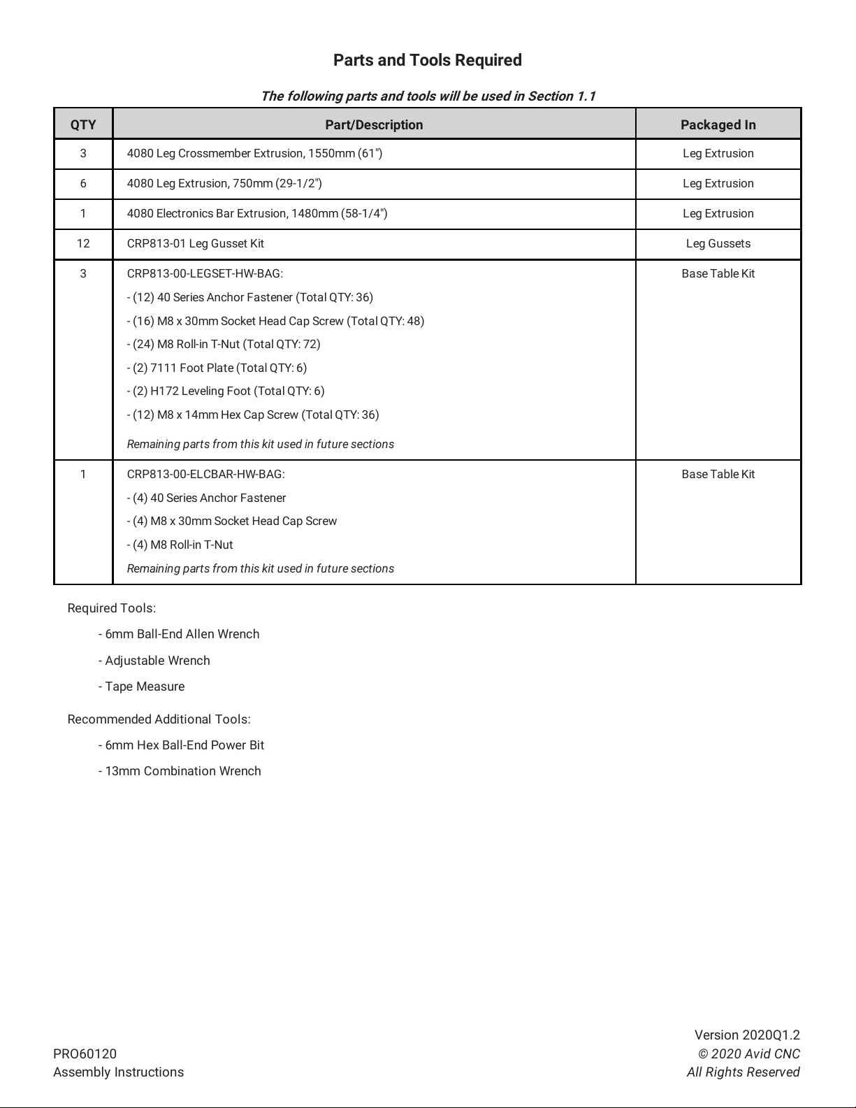
Parts and Tools Required
The following parts and tools will be used in Section 1.1
QTY Part/Description Packaged In
3 4080 Leg Crossmember Extrusion, 1550mm (61") Leg Extrusion
6 4080 Leg Extrusion, 750mm (29-1/2") Leg Extrusion
1 4080 Electronics Bar Extrusion, 1480mm (58-1/4") Leg Extrusion
12 CRP813-01 Leg Gusset Kit Leg Gussets
3 CRP813-00-LEGSET-HW-BAG: Base Table Kit
- (12) 40 Series Anchor Fastener (Total QTY: 36)
- (16) M8 x 30mm Socket Head Cap Screw (Total QTY: 48)
- (24) M8 Roll-in T-Nut (Total QTY: 72)
- (2) 7111 Foot Plate (Total QTY: 6)
- (2) H172 Leveling Foot (Total QTY: 6)
- (12) M8 x 14mm Hex Cap Screw (Total QTY: 36)
Remaining parts from this kit used in future sections
1 CRP813-00-ELCBAR-HW-BAG: Base Table Kit
- (4) 40 Series Anchor Fastener
- (4) M8 x 30mm Socket Head Cap Screw
- (4) M8 Roll-in T-Nut
Remaining parts from this kit used in future sections
Required Tools:
- 6mm Ball-End Allen Wrench
- Adjustable Wrench
- Tape Measure
Recommended Additional Tools:
- 6mm Hex Ball-End Power Bit
- 13mm Combination Wrench
PRO60120
Assembly Instructions
Version 2020Q1.2
© 2020 Avid CNC
All Rights Reserved
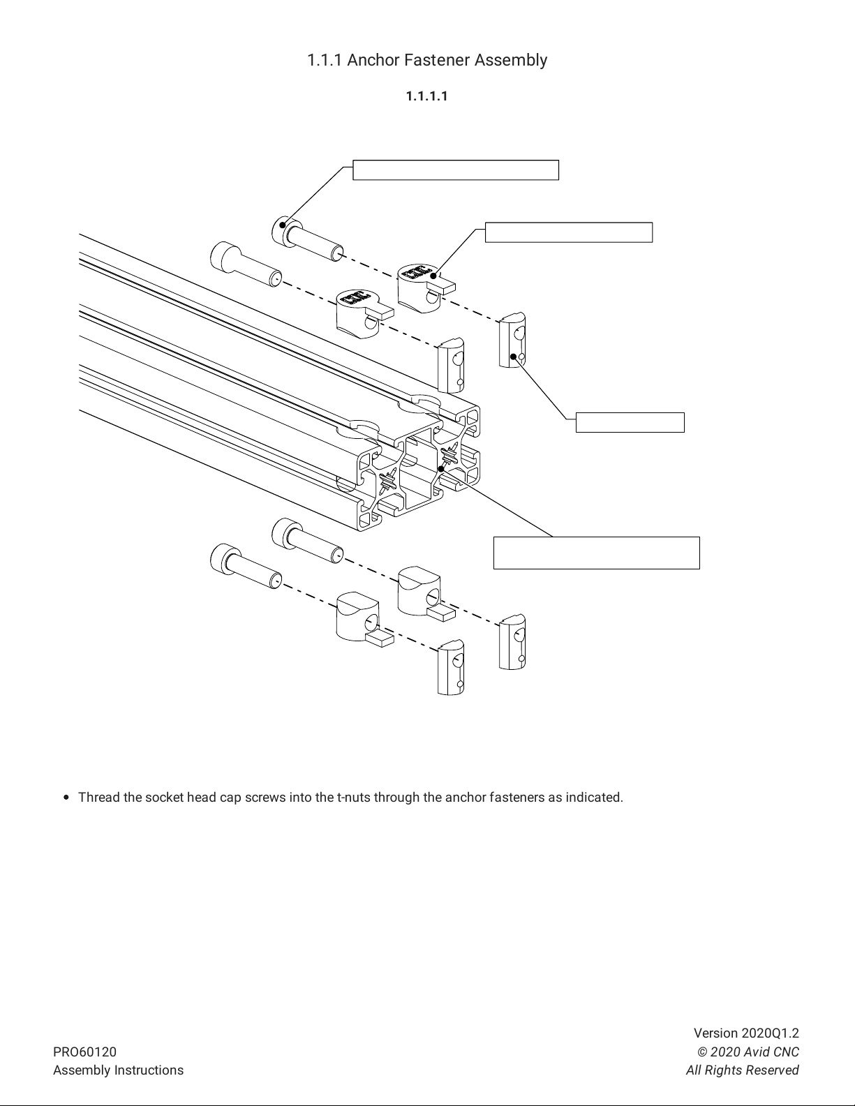
1.1.1 Anchor Fastener Assembly
1.1.1.1
Thread the socket head cap screws into the t-nuts through the anchor fasteners as indicated.
M8 x 30mm Socket Head Cap Screw
4080 Leg Crossmember Extrusion,
1550mm (61")
40 Series Anchor Fastener
M8 Roll-in T-Nut
PRO60120
Assembly Instructions
Version 2020Q1.2
© 2020 Avid CNC
All Rights Reserved


1.1.2 Leveling Feet Installation
1.1.2.1
Install a foot assembly onto each 750mm (29-1/2") leg extrusion as indicated.
H172 Leveling Foot
M8 x 30mm Socket Head Cap Screw
M16 Hex Nut
7111 Foot Plate
4080 Leg Extrusion, 750mm (29-1/2")
Assembly Note
It is recommended to first install the foot plate onto the extrusion before threading in the leveling foot.
PRO60120
Assembly Instructions
Version 2020Q1.2
© 2020 Avid CNC
All Rights Reserved

1.1.2.2
Repeat the previous steps for each of the 750mm (29-1/2") leg extrusions as indicated.
Assembly Note
Initially thread the leveling feet all of the way into the foot plate. After machine assembly, final adjustments will be made in
the table leveling procedure. (www.avidcnc.com/leveling-squaring-and-tramming-your-cnc-machine-p-438.html)
PRO60120
Assembly Instructions
Version 2020Q1.2
© 2020 Avid CNC
All Rights Reserved

Table of contents
Other Avid CNC Control System manuals


