iv
5.2.4 Base I/O Unit Input/Output Specifications.................................................... 53
5.2.5 Connection of Servo Amplifier...................................................................... 55
5.2.6 Connection of Encoder ................................................................................ 55
5.2.7 Connection of Sensor Signal (skip).............................................................. 56
5.3 Connection of Card-sized I/O .............................................................................. 57
5.3.1 Examples of Card-sized I/O Usage.............................................................. 57
5.3.2 Card-sized I/O Specifications....................................................................... 58
5.3.3 Card-sized I/O Connector Pin Assignment .................................................. 59
5.3.4 Precautions for Wiring Card-sized I/O.......................................................... 59
5.3.5 Card-sized I/O Input/Output Circuit.............................................................. 60
5.3.6 Installation of Card-sized I/O........................................................................ 62
5.3.7 Card-sized Analog I/O Connection............................................................... 63
5.4 Scan I/O............................................................................................................... 65
5.4.1 Types of Scan I/O ........................................................................................ 65
5.4.2 Scan I/O Connector Layout Drawing............................................................ 65
5.4.3 Scan I/O Connector...................................................................................... 66
5.4.4 Scan I/O Station No. Setting........................................................................ 67
5.4.5 Scan I/O Connection.................................................................................... 68
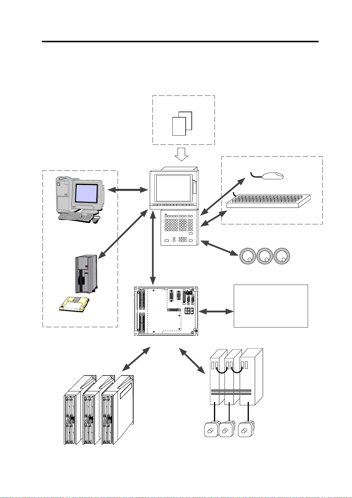
CHAPTER 6 CONNECTION OF REMOTE I/O UNIT .................................................... 73
6.1 Outline of Remote I/O Unit................................................................................... 73
6.2 Names of Each Remote I/O Unit Section ............................................................ 74
6.3 Connection of Remote I/O Power........................................................................ 75
6.4 Outline of Digital Signal Input Circuit................................................................... 76
6.5 Outline of Digital Signal Output Circuit ................................................................ 78
6.6 Outline of Analog Signal Output Circuit............................................................... 79
6.7 Outline of Analog Signal Input Circuit.................................................................. 80
6.8 Connection of FCUA-DX10 /13/14 Unit and Machine Control Signal............ 81
6.9 Connection of FCUA-DX11 Unit and Machine Control Signal.......................... 83
6.10 Connection of FCUA-DX12 Unit and Machine Control Signal.......................... 85
6.11 Connection of FCUA-DX13 Unit and Handle.................................................... 87
6.12 Outline of FCUA-DX13 Unit Pulse Input Circuit................................................ 88
6.13 Connection of FCUA-DX14 Unit and Analog Input/Output Signal.................... 89
6.14 Setting of Channel No. when Using Multiple Remote I/O Units........................... 90
6.15 Cables ................................................................................................................. 91
APPENDIX 1 INSTALLATION DIMENSIONS............................................................... 92
Appendix 1.1 Control Unit Outline Drawing...................................................... 92
Appendix 1.2 Display Unit Outline Drawing...................................................... 93
Appendix 1.3 External Power Supply Unit (PD25) Outline Drawing................. 94
Appendix 1.4 Base I/O Unit Outline Drawing ................................................... 95
Appendix 1.5 Remote I/O Unit Outline Drawing............................................... 97
Appendix 1.6 Card-sized I/O Outline Drawing.................................................. 98
Appendix 1.7 Scan I/O Card Outline Drawing.................................................. 99
Appendix 1.8 Manual Pulse Generator (HD60) Outline Drawing..................... 100
Appendix 1.9 Encoder (OSE-1024-3-15-68) Outline Drawing.......................... 101
Appendix 1.10 Floppy Disk Drive Unit Outline Drawing..................................... 102
Appendix 1.11 F Installation Plate Outline Drawing...........................................103
Appendix 1.12 External Hard Disk Drive Unit Outline Drawing.......................... 103
Appendix 1.13 NC Keyboard Outline Drawing................................................... 104
Appendix 1.14 Grounding Plate and Clamp Fitting Outline Drawings................ 105
APPENDIX 2 CABLE MANUFACTURING DRAWINGS............................................... 106
Appendix 2.1 Cable type name: SH21 cable (Servo amplifier) ................. 107
Appendix 2.2 Cable type name: SH41 cable (Remote I/O)....................... 107
Appendix 2.3 Cable type name: FCUA-R211 cable