Avid CNC 3 HP User manual

Plug and Play Spindle / VFD Retrofit Guide
v2021Q1.1
Plug and Play
Retrofit Guide
Version 2021Q1.1
© 2021 Avid CNC
All Rights Reserved
Plug and Play NEMA 23 and NEMA 34 CNC Control Systems purchased prior to Nov 2015 did not include the "SP/THC"
connector by default. Please Contact Us and we will provide this connector at no cost.
If you are using Mach3 CNC controller software, please refer to our Mach3 CRP800 VFD Retrot Guide.
(https://www.avidcnc.com/dl/cad.2018Q3/CRP800_Retrot_Guide_v2018Q3_1.pdf)
SP/THC Connector Installation
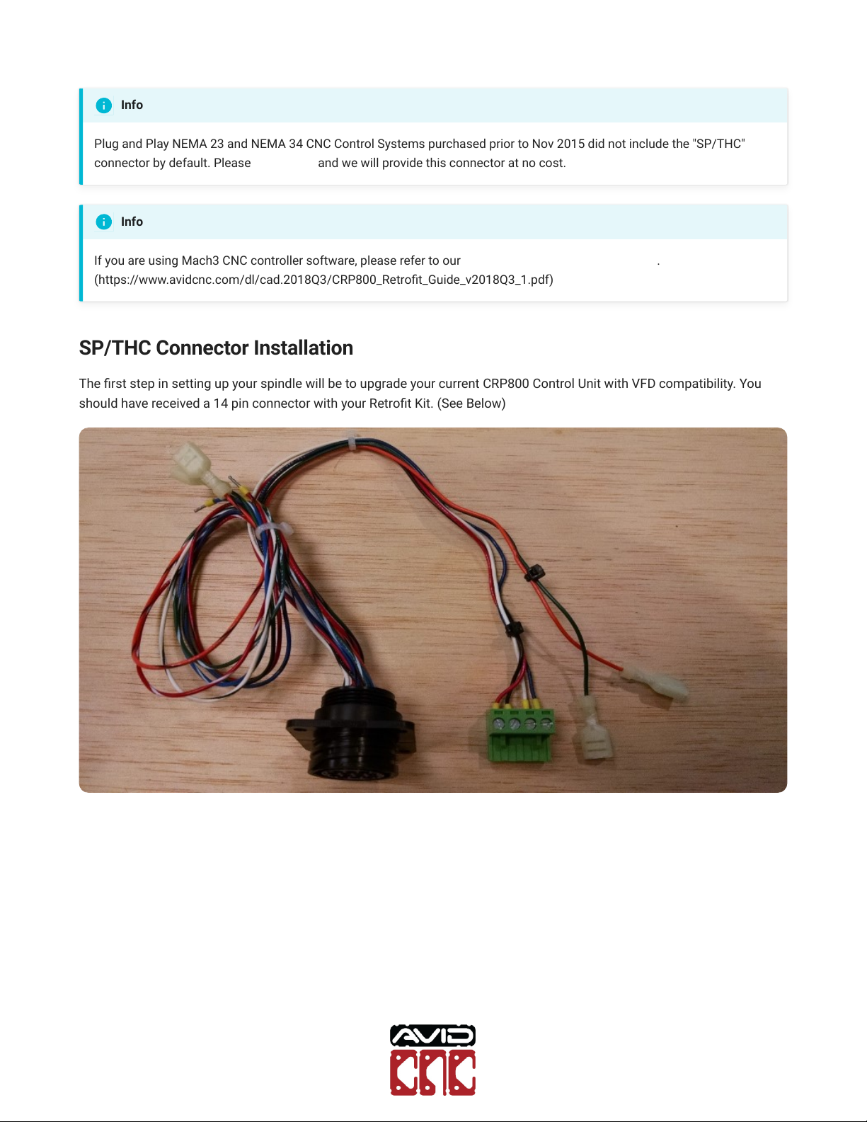
The rst step in setting up your spindle will be to upgrade your current CRP800 Control Unit with VFD compatibility. You
should have received a 14 pin connector with your Retrot Kit. (See Below)
Info
Info

Plug and Play
Retrofit Guide
Version 2021Q1.1
© 2021 Avid CNC
All Rights Reserved
This connector will be zip tied to separate out the 4 pins used for speed and fault signaling from the relay wiring. (See
Below)

Plug and Play
Retrofit Guide
Version 2021Q1.1
© 2021 Avid CNC
All Rights Reserved
To install this 14 pin connector, rst remove the SP/THC port cover on your CRP800 Control Unit. (See Below)
Next install the 14 pin connector from the back side of the gland plate, with the square plastic ange on the inside of the
Control Unit. (See Below)

Plug and Play
Retrofit Guide
Version 2021Q1.1
© 2021 Avid CNC
All Rights Reserved
Now using the supplied #6-32 screws and nuts, secure the 14 pin connector to the gland plate. (See Below)
The 14 pin connector must now be wired to the break out board inside of the Control Unit. Install the four pin SUPU
connector onto the break out board in the orientation and position shown.

Plug and Play
Retrofit Guide
Version 2021Q1.1
© 2021 Avid CNC
All Rights Reserved
Then, install the Orange and Green quick disconnects on the 3rd relay of the red break out board mounted to the gland plate
(furthest on the left when facing down into the control unit, closest to the relay sockets on the gland plate). Note, you may
have to crimp down on the QDC's to create a solid connection.
Your CRP800 Control Unit is now ready to connect to the VFD via the grey 14 pin cable included with your Spindle and VFD
package.

Plug and Play
Retrofit Guide
Version 2021Q1.1
© 2021 Avid CNC
All Rights Reserved
VFD Control Box Connections
14-Pin SP/THC Cable
CNC Control Box VFD Control Box
If you are upgrading to the 8.7 HP Plug and Play Spindle / VFD system, ensure you use the new 14-pin cable that came with
your 8.7 HP system.
Connect the 14-pin SP/THC cable to your Spindle / VFD System and CNC Control Unit.
8.7 HP Plug and Play Spindle / VFD System
Plug and Play
Retrofit Guide
Version 2021Q1.1
© 2021 Avid CNC
All Rights Reserved
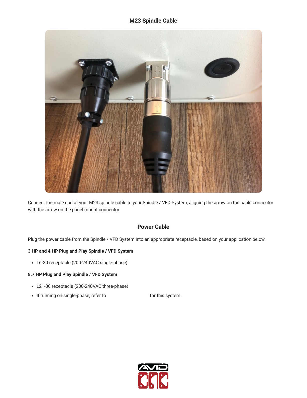
M23 Spindle Cable
Connect the male end of your M23 spindle cable to your Spindle / VFD System, aligning the arrow on the cable connector
with the arrow on the panel mount connector.
Power Cable
Plug the power cable from the Spindle / VFD System into an appropriate receptacle, based on your application below.
3 HP and 4 HP Plug and Play Spindle / VFD System
L6-30 receptacle (200-240VAC single-phase)
8.7 HP Plug and Play Spindle / VFD System
L21-30 receptacle (200-240VAC three-phase)
If running on single-phase, refer to power requirements for this system.
Plug and Play
Retrofit Guide
Version 2021Q1.1
© 2021 Avid CNC
All Rights Reserved
Spindle Connection
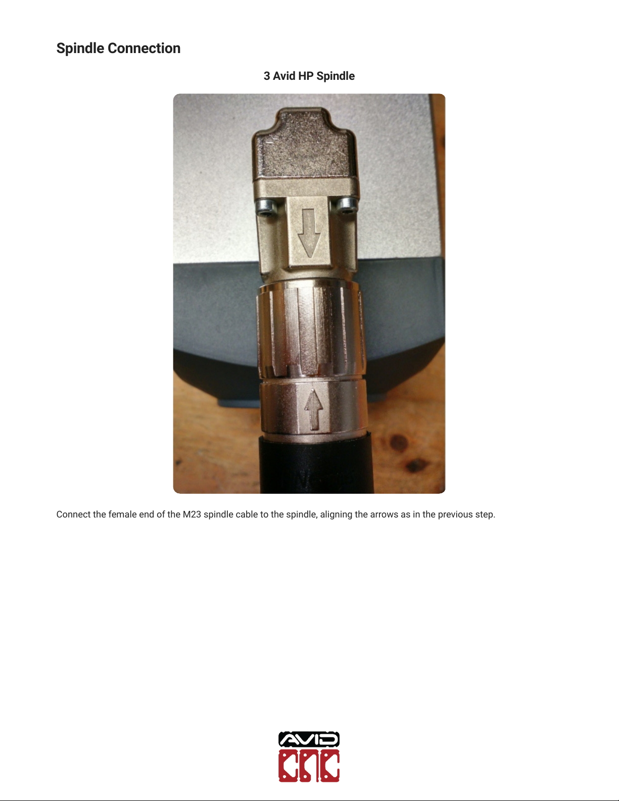
3 Avid HP Spindle
Connect the female end of the M23 spindle cable to the spindle, aligning the arrows as in the previous step.

Plug and Play
Retrofit Guide
Version 2021Q1.1
© 2021 Avid CNC
All Rights Reserved
4 Avid HP Spindle
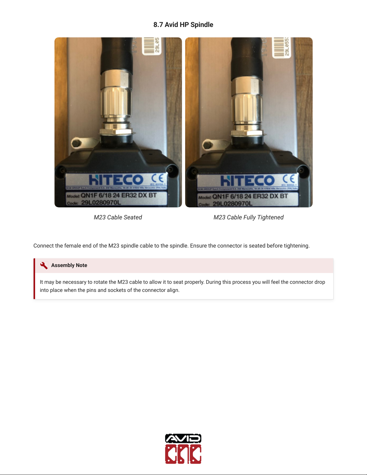
M23 Cable Seated M23 Cable Fully Tightened
Connect the female end of the M23 spindle cable to the spindle. Ensure the connector is seated before tightening.
It may be necessary to rotate the M23 cable to allow it to seat properly. During this process you will feel the connector drop
into place when the pins and sockets of the connector align.
Assembly Note
Plug and Play
Retrofit Guide
Version 2021Q1.1
© 2021 Avid CNC
All Rights Reserved
8.7 Avid HP Spindle
M23 Cable Seated M23 Cable Fully Tightened
Connect the female end of the M23 spindle cable to the spindle. Ensure the connector is seated before tightening.
It may be necessary to rotate the M23 cable to allow it to seat properly. During this process you will feel the connector drop
into place when the pins and sockets of the connector align.
Assembly Note
Plug and Play
Retrofit Guide
Version 2021Q1.1
© 2021 Avid CNC
All Rights Reserved
Mach4 Setup
Use of the 4 HP Avid CNC spindle requires version 2.2.2 or newer of Mach4 and use of the 8.7 HP Avid CNC spindle requires
version 2.1.0 or newer of Mach4. If you need to update your installation of Mach4, please visit the Mach4 downloads page
and Contact Us with any questions.
After the physical connections are complete, the next step is to congure Mach4 for your spindle. If you have not
congured Mach4 for your machine, follow the steps in the CNC Software Setup Guide.
If you are currently using Mach4, you will need to update your Mach4 conguration using the Avid CNC Mach4
Conguration menu. When selecting a Cutting Tool, choose "Spindle" (or "Spindle / Plasma" for dual-use machines) and the
appropriate Spindle Type.
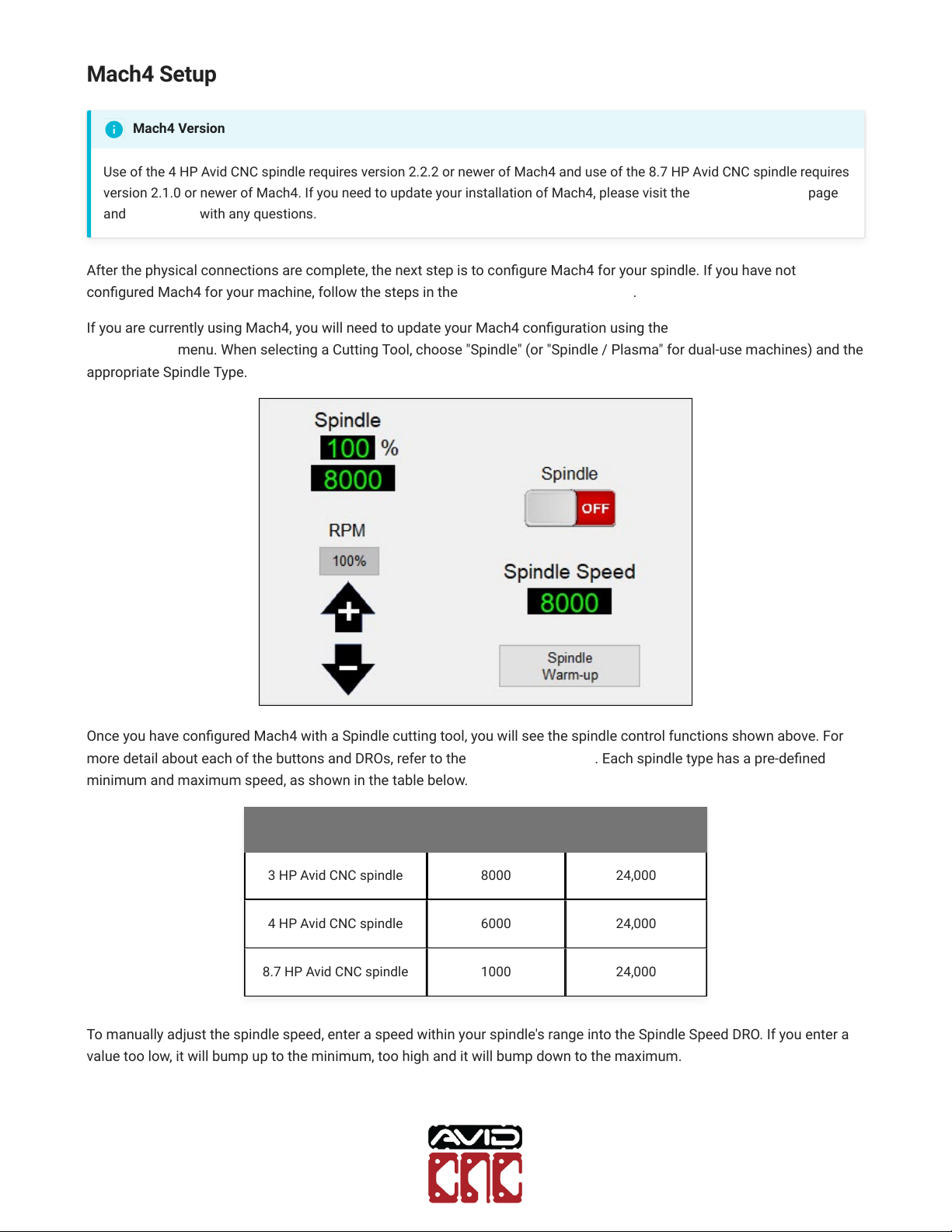
Once you have congured Mach4 with a Spindle cutting tool, you will see the spindle control functions shown above. For
more detail about each of the buttons and DROs, refer to the Mach4 Users Guide. Each spindle type has a pre-dened
minimum and maximum speed, as shown in the table below.
Spindle Type Min Speed (RPM) Max Speed (RPM)
3 HP Avid CNC spindle 8000 24,000
4 HP Avid CNC spindle 6000 24,000
8.7 HP Avid CNC spindle 1000 24,000
To manually adjust the spindle speed, enter a speed within your spindle's range into the Spindle Speed DRO. If you enter a
value too low, it will bump up to the minimum, too high and it will bump down to the maximum.
Mach4 Version

Plug and Play
Retrofit Guide
Version 2021Q1.1
© 2021 Avid CNC
All Rights Reserved
Once you have input a valid spindle speed, click the Spindle toggle button to turn the spindle on and run it at that speed
(Mach4 will need to be enabled to turn the spindle on).
Check that you can adjust speed while the spindle is on by entering various speeds (between your spindle's min and max
speeds) into Spindle Speed DRO and hit enter.
If the spindle responds to these speed commands, your VFD and Spindle package is ready for use!
If you experience any trouble while following this guide, please feel free to Contact Us.
This manual suits for next models
2


