Sony DRV-1000 User manual

1998 by Sony Corporation
3-862-560-11(1)
DVCAM Drive
User’s Guide
Mode d’emploi
EN
F
DRV-1000/1000P

Owner’s Record
The model number is located on the bottom and front of the unit
and the serial number on the bottom.
Record the serial number in the space provided below.
Refer to these numbers whenever you call upon your Sony
dealer regarding this product.
Model No.
DRV-1000/1000P
Serial No. _________________
WARNING
To prevent fire or shock hazard, do not
expose the unit to rain or moisture.
CAUTION
You are cautioned that any changes or modifications not
expressly approved in this manual could void your authority to
operate this equipment.
DRV-1000 only
Note
This equipment has been tested and found to comply with the
limits for a Class B digital device, pursuant to Part 15 of the
FCC Rules. These limits are designed to provide reasonable
protection against harmful interference in a residential installa-
tion. This equipment generates, uses, and can radiate radio
frequency energy and, if not installed and used in accordance
with the instructions, may cause harmful interference to radio
communications. However, there is no guarantee that interfer-
ence will not occur in a particular installation. If this equipment
does cause harmful interference to radio or television reception,
which can be determined by turning the equipment off and on,
the user is encouraged to try to correct the interference by one
or more of the following measures:
• Reorient or relocate the receiving antenna.
• Increase the separation between the equipment and receiver.
• Connect the equipment into an outlet on a circuit different from
that to which the receiver is connected.
• Consult the dealer or an experienced radio/TV technician for
help.

Declaration of Conformity
Trade Name: SONY
Model No.: DRV-1000
Responsible Party: Sony Electronics Inc.
Address: 1 Sony Drive, Park Ridge, NJ.07656 USA
Telephone No.: 201-930-6970
This device complies with Part 15 of the FCC Rules. Operation is
subject to the following two conditions: (1) This device may not
cause harmful interference, and (2) this devise must accept any
interference received, including interference that may cause
undesired operation.
Caution
Television programs, films, video tapes and other materials
may be copyrighted.
Unauthorized recording of such material may be contrary to the
provisions of the copyright laws. Also, use of this recorder with
cable television transmission may require authorization from the
cable television transmission and/or program owner.


1
EN
Contents
English
EN
Introduction...................................................................... 2
Features ................................................................. 2
Precautions ............................................................ 3
Notes on cassettes.................................................. 4
Condensation ......................................................... 5
Location and function of parts ....................................... 6
Installation........................................................................ 8
Before you start ..................................................... 8
Installing the drive............................................... 10
Software installation............................................ 12
Operation........................................................................ 13
Reference ....................................................................... 15
Indicators ............................................................. 15
Maintenance and troubleshooting ....................... 16
Compatibility of DVCAM and DV formats........ 17
Differences between DVCAM and
DV formats................................................ 17
Compatibility of DVCAM and DV formats... 18
Playback compatibility ................................... 18
Editing compatibility using DV connectors ... 19
Limitations on editing .................................... 20
Cassettes and playback modes ............................ 21
Selecting cassette types .................................. 21
When you play back ....................................... 21
Specifications ................................................................ 24

2
EN
Introduction
Features
The DRV-1000/1000P DVCAM drive is designed to be
installed in an IBM PC/AT, Apple Macintosh, or compatible
computer. In combination with an appropriate digital video
codec card, it provides a full range of digital video playback
and recording functions. It can also be used with an analog
video card.
• Accepts mini DVCAM cassettes.
• In addition to the standard digital video interface connector,
has analog video, audio, and S-video outputs.
• Extra control functions are provided by a LANC interface
jack and ejection control jack.
• Provides full tape transport functions: play, record, fast
forward, rewind, variable speed playback, and pause.
• Software ejection control (when EJECT jack is connected).
• Mounts in standard half-height 51/4-inch bay, and uses
standard internal power supply.
• Front panel indicators show operating state, and also give
diagnostic information (see table on page 15).
IBM PC, PC/XT, and PC/AT are registered trademarks of International Business Machines
Corporation.
Apple and Macintosh are registered trademarks of Apple Computer, Inc.
.....................................................................................................................................

3
EN
Precautions
Do not install the unit in a place subject to direct
sunlight or heat sources
If you do, its cabinet, mechanical parts, etc., may be damaged.
Do not install the unit in an extremely hot place
If the unit is left in a car parked with its windows closed
(especially in summer), its cabinet may be damaged or it may
not work correctly.
Install the unit only in the horizontal position
The unit is not designed to operate in the vertical position or at
an angle.
If the unit is brought directly from a cold to a warm
location
Moisture may condense inside the unit and cause damage to the
video head and tape. If you use the unit in a place subject to
direct cold currents from an air-conditioner, moisture may also
condense inside the unit.
Do not place a heavy objects on the unit
The cabinet may be damaged, or the unit may not work
correctly.
Do not handle the unit roughly
Avoid rough handling or mechanical shock.
Do not put magnetic objects close to the unit
Magnetic fields may damage the recording.
Checking the drive heads
A digital video drive is a high-precision piece of equipment
that records and plays back the pictures on a magnetic tape. In
particular, over long-term use the video head and other
mechanical parts may become dirty or worn. If the picture
quality deteriorates, or a block mosaic effect appears, carry out
head cleaning. (See “Maintenance and troubleshooting” on
page 16.)
4
EN
Notes on cassettes
This drive accepts mini DVCAM cassettes.
Recommended cassettes
You are recommended to use Sony cassettes for optimum
quality. Lower quality cassettes may give inferior recording
quality.
Color systems
DRV-1000: This drive can only play back NTSC recordings,
and not PAL or SECAM.
DRV-1000P: This drive can only play back PAL recordings,
and not NTSC or SECAM.
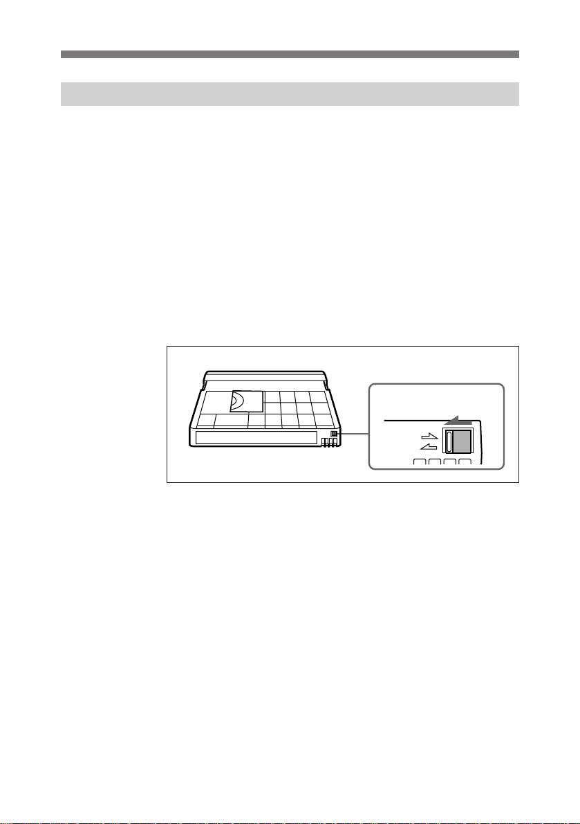
Write-protecting the tape
Slide the write-protect tab on the cassette to the left (“SAVE”
position) so that the red portion is visible.
Treat cassettes carefully, and keep them clean. Do not insert
anything into the small holes, and do not open the protective
cover or touch the tape.
REC
SAVE
Write-protect tab
Introduction

5
EN
Avoid touching the electrical contacts on the outside of the
cassette. Clean the contacts with a cotton swab about once
every ten eject operations.
Attach labels only in the positions shown.
Storing cassettes
After using a cassette, rewind it to the beginning of the tape,
then store it in its case, in an upright position.
Condensation
All video decks are susceptible to condensation. If moisture
condenses on the rotating drum, the tape may stick, and both
the tape and heads may be damaged.
Condensation occurs when the metal parts are colder than
moisture-laden surrounding air. If you move the drive from a
cold place to a warmer one, always allow sufficient time for
any condensation to evaporate.
If the drive detects condensation, it stops operating, and the
pause indicator flashes rapidly.
Label positions
Electrical contacts
6
EN
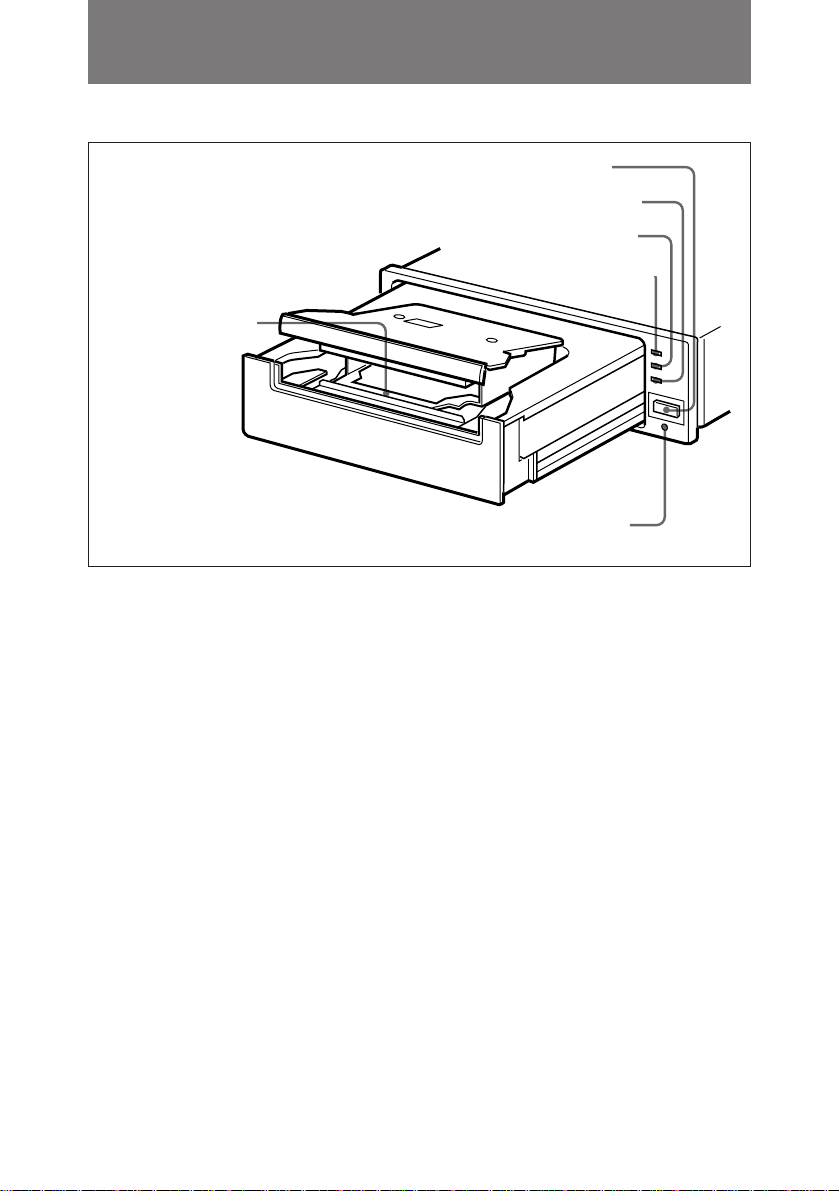
Front view (with drawer ejected)
Location and function of parts
1Cassette holder
Accepts a mini DVCAM cassette
when the cassette drawer is open.
2PAUSE indicator
Lights when the drive is paused.
3REC (recording) indicator
Lights when the drive is recording.
4TAPE RUN indicator
Lights when the tape transport is
operating.
For details of errors and other
indications shown by combinations of
the indicators, see the table on page
15.
5Eject button
Press this button to eject the cassette
drawer.
6Reset button
In the event of a problem with the
drive, insert a fine screwdriver or
similar instrument into the hole, and
press to reset all data in the drive.
1Cassette holder
2PAUSE indicator
4TAPE RUN indicator
5Eject button
6Reset button
3REC (recording)
indicator
This manual suits for next models
1
Table of contents
Languages:
Other Sony DC Drive manuals


Popular DC Drive manuals by other brands


ABB
ABB RSYC-01 user manual

Rockwell Automation
Rockwell Automation PowerFlex 700S Programming manual

WEG
WEG DeviceNet CFW500 user manual

Siemens
Siemens SINAMICS G List manual

Siemens
Siemens SINAMICS SM150 6SL3815-7NP41-0AA1 Operating instructions & installation instructions

SOMFY
SOMFY JR RU 30 instructions