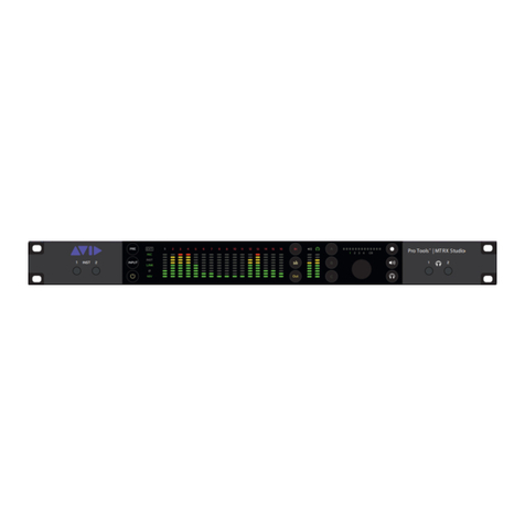
Avid Technology Pro Tools MTRX User manual

Pro Tools®| MTRX Studio Operation Guide

Legal Notices
© 2020 Avid Technology, Inc., (“Avid”), all rights reserved. This guide may not be duplicated in whole or in part without the written consent of Avid.
For a current and complete list of Avid trademarks visit: www.avid.com/legal/trademarks-and-other-notices
Bonjour, the Bonjour logo, and the Bonjour symbol are trademarks of Apple Computer, Inc.
Thunderbolt and the Thunderbolt logo are trademarks of Intel Corporation in the U.S. and/or other countries.
This product may be protected by one or more U.S. and non-U.S. patents. Details are available at www.avid.com/patents.
Product features, specifications, system requirements, and availability are subject to change without notice.
Guide Part Number 9329-66069-00 REV B 4/20

MTRX Studio Operation Guide iii
Introduction . . . . . . . . . . . . . . . . . . . . . . . . . . . . . . . . . . . . . . . . . . . . . . . . . . . . . . . . . . . . . . . . . . . . . . . . . . . . . . . . . . . . . . 1
Pro Tools | MTRX Studio . . . . . . . . . . . . . . . . . . . . . . . . . . . . . . . . . . . . . . . . . . . . . . . . . . . . . . . . . . . . . . . . . . . . . . 1
Before You Start. . . . . . . . . . . . . . . . . . . . . . . . . . . . . . . . . . . . . . . . . . . . . . . . . . . . . . . . . . . . . . . . . . . . . . . . . . . . . 3
System Requirements and Compatibility Information . . . . . . . . . . . . . . . . . . . . . . . . . . . . . . . . . . . . . . . . . . . . . . . 3
Conventions Used in Pro Tools Documentation. . . . . . . . . . . . . . . . . . . . . . . . . . . . . . . . . . . . . . . . . . . . . . . . . . . . 3
Resources. . . . . . . . . . . . . . . . . . . . . . . . . . . . . . . . . . . . . . . . . . . . . . . . . . . . . . . . . . . . . . . . . . . . . . . . . . . . . . . . . . 4
Pro Tools | MTRX Studio Operation . . . . . . . . . . . . . . . . . . . . . . . . . . . . . . . . . . . . . . . . . . . . . . . . . . . . . . . . . . . . . . . . 5
Pro Tools | MTRX Studio Front Panel . . . . . . . . . . . . . . . . . . . . . . . . . . . . . . . . . . . . . . . . . . . . . . . . . . . . . . . . . . . . 5
Instrument and Microphone Inputs 1 and 2 . . . . . . . . . . . . . . . . . . . . . . . . . . . . . . . . . . . . . . . . . . . . . . . . . . . . . . . 7
Control Room and Headphone Monitoring. . . . . . . . . . . . . . . . . . . . . . . . . . . . . . . . . . . . . . . . . . . . . . . . . . . . . . . . 7
Pro Tools | MTRX Studio Back Panel Connections . . . . . . . . . . . . . . . . . . . . . . . . . . . . . . . . . . . . . . . . . . . . . . . . . . 9
Pro Tools | MTRX Studio Back Panel . . . . . . . . . . . . . . . . . . . . . . . . . . . . . . . . . . . . . . . . . . . . . . . . . . . . . . . . . . . . 9
Reconfig Button . . . . . . . . . . . . . . . . . . . . . . . . . . . . . . . . . . . . . . . . . . . . . . . . . . . . . . . . . . . . . . . . . . . . . . . . . . . . 11
DADman Software . . . . . . . . . . . . . . . . . . . . . . . . . . . . . . . . . . . . . . . . . . . . . . . . . . . . . . . . . . . . . . . . . . . . . . . . . . . . . . . 13
Assigning the IP Address for your Computer and MTRX Studio. . . . . . . . . . . . . . . . . . . . . . . . . . . . . . . . . . . . . . 13
DADman Configuration Files. . . . . . . . . . . . . . . . . . . . . . . . . . . . . . . . . . . . . . . . . . . . . . . . . . . . . . . . . . . . . . . . . . 14
DADman Settings Menu. . . . . . . . . . . . . . . . . . . . . . . . . . . . . . . . . . . . . . . . . . . . . . . . . . . . . . . . . . . . . . . . . . . . . . 15
DADman Window . . . . . . . . . . . . . . . . . . . . . . . . . . . . . . . . . . . . . . . . . . . . . . . . . . . . . . . . . . . . . . . . . . . . . . . . . . . 16
Monitor Profiles . . . . . . . . . . . . . . . . . . . . . . . . . . . . . . . . . . . . . . . . . . . . . . . . . . . . . . . . . . . . . . . . . . . . . . . . . . . . . . . . . 28
Monitor Profile Files. . . . . . . . . . . . . . . . . . . . . . . . . . . . . . . . . . . . . . . . . . . . . . . . . . . . . . . . . . . . . . . . . . . . . . . . . 28
Groups Page. . . . . . . . . . . . . . . . . . . . . . . . . . . . . . . . . . . . . . . . . . . . . . . . . . . . . . . . . . . . . . . . . . . . . . . . . . . . . . . 31
Fold Down Page . . . . . . . . . . . . . . . . . . . . . . . . . . . . . . . . . . . . . . . . . . . . . . . . . . . . . . . . . . . . . . . . . . . . . . . . . . . . 37
Group Formats . . . . . . . . . . . . . . . . . . . . . . . . . . . . . . . . . . . . . . . . . . . . . . . . . . . . . . . . . . . . . . . . . . . . . . . . . . . . . 38
Mom Page. . . . . . . . . . . . . . . . . . . . . . . . . . . . . . . . . . . . . . . . . . . . . . . . . . . . . . . . . . . . . . . . . . . . . . . . . . . . . . . . . 40
MTRX Studio Page . . . . . . . . . . . . . . . . . . . . . . . . . . . . . . . . . . . . . . . . . . . . . . . . . . . . . . . . . . . . . . . . . . . . . . . . . . 41
SPQ Processing . . . . . . . . . . . . . . . . . . . . . . . . . . . . . . . . . . . . . . . . . . . . . . . . . . . . . . . . . . . . . . . . . . . . . . . . . . . . . . . . . 43
EQ . . . . . . . . . . . . . . . . . . . . . . . . . . . . . . . . . . . . . . . . . . . . . . . . . . . . . . . . . . . . . . . . . . . . . . . . . . . . . . . . . . . . . . . 43
Configuring Bass Management . . . . . . . . . . . . . . . . . . . . . . . . . . . . . . . . . . . . . . . . . . . . . . . . . . . . . . . . . . . . . . . . 45
Controlling MTRX Studio Preamps from Pro Tools (Mac Only) . . . . . . . . . . . . . . . . . . . . . . . . . . . . . . . . . . . . . . 48
Configuring Audio MIDI Setup. . . . . . . . . . . . . . . . . . . . . . . . . . . . . . . . . . . . . . . . . . . . . . . . . . . . . . . . . . . . . . . . . 48
Configure DADman . . . . . . . . . . . . . . . . . . . . . . . . . . . . . . . . . . . . . . . . . . . . . . . . . . . . . . . . . . . . . . . . . . . . . . . . . 49
Configure Pro Tools Software . . . . . . . . . . . . . . . . . . . . . . . . . . . . . . . . . . . . . . . . . . . . . . . . . . . . . . . . . . . . . . . . . 49
Controlling MTRX Studio from Pro Tools (or from a Control Surface) . . . . . . . . . . . . . . . . . . . . . . . . . . . . . . . . . 50
Contents

MTRX Studio Operation Guide
iv
Appendix A. Specifications. . . . . . . . . . . . . . . . . . . . . . . . . . . . . . . . . . . . . . . . . . . . . . . . . . . . . . . . . . . . . . . . . . . . . . . . . . 52
Audio Specifications . . . . . . . . . . . . . . . . . . . . . . . . . . . . . . . . . . . . . . . . . . . . . . . . . . . . . . . . . . . . . . . . . . . . . . . . 52
Electrical Specifications. . . . . . . . . . . . . . . . . . . . . . . . . . . . . . . . . . . . . . . . . . . . . . . . . . . . . . . . . . . . . . . . . . . . . . 54
Mechanical Specifications . . . . . . . . . . . . . . . . . . . . . . . . . . . . . . . . . . . . . . . . . . . . . . . . . . . . . . . . . . . . . . . . . . . . 54
Environmental Specifications . . . . . . . . . . . . . . . . . . . . . . . . . . . . . . . . . . . . . . . . . . . . . . . . . . . . . . . . . . . . . . . . . 54
Appendix B. Network Fundamentals . . . . . . . . . . . . . . . . . . . . . . . . . . . . . . . . . . . . . . . . . . . . . . . . . . . . . . . . . . . . . . . . . . 55
What is a network? . . . . . . . . . . . . . . . . . . . . . . . . . . . . . . . . . . . . . . . . . . . . . . . . . . . . . . . . . . . . . . . . . . . . . . . . . . 55
Infrastructure . . . . . . . . . . . . . . . . . . . . . . . . . . . . . . . . . . . . . . . . . . . . . . . . . . . . . . . . . . . . . . . . . . . . . . . . . . . . . . 56
Addressing . . . . . . . . . . . . . . . . . . . . . . . . . . . . . . . . . . . . . . . . . . . . . . . . . . . . . . . . . . . . . . . . . . . . . . . . . . . . . . . . 56
Appendix C. I/O Delays . . . . . . . . . . . . . . . . . . . . . . . . . . . . . . . . . . . . . . . . . . . . . . . . . . . . . . . . . . . . . . . . . . . . . . . . . . . . . 59
MTRX Studio Input to Output Delays. . . . . . . . . . . . . . . . . . . . . . . . . . . . . . . . . . . . . . . . . . . . . . . . . . . . . . . . . . . . 59

Chapter 1: Introduction 1
Chapter 1: Introduction
Pro Tools | MTRX Studio
Welcome to Pro Tools®| MTRX Studio. MTRX Studio is an extremely versatile multi-channel audio interface for Pro Tools | HDX
and Pro Tools | HD Native systems. MTRX Studio supports 16- and 24-bit audio with sample rates of 44.1, 48, 88.2, 96, 176.4, and
192 kHz. MTRX Studio provides two DigiLink™ Mini ports for up to 64 input and output channels with Pro Tools. MTRX Studio
provides 16 analog line inputs, 16 analog line outputs, two analog monitor outputs, two headphone outputs, and two analog inputs
for microphones or instruments. It also provides a 64 I/O channels Dante®IP Audio interface and 16 channels of ADAT™I/O,
Word Clock and Loop sync synchronization, and an input for a foot switch (for various DADman functions, such as talk back re-
mote control). Additionally, MTRX Studio provides built-in SPQ processing for room tuning, bass management, and equalizing of
cue and monitor signals.
MTRX Studio can be used a traditional recording interface, with mic and line analog I/O, phantom power, and two headphone jacks
on the front panel. MTRX Studio can also be used as a monitor controller output device for immersive audio post production ap-
plications with up to 9.1.6 channel layouts. Pro Mon monitor control functionality is available for EUCON™-enabled Avid devices
with MTRX Studio using DADman software.
MTRX Studio Features
MTRX Studio provides up to 64 discrete channels of audio for Pro Tools with two DigiLink Mini ports (Primary and Primary/Ex-
pansion).
Analog I/O
• 2 Instrument/Microphone inputs (with preamps)
• 16 analog line inputs (DB25)
• 16 analog line outputs (DB25)
• 2 monitor outputs (balanced 1/4-inch)
• 2 stereo headphone outputs
Digital I/O
• 64x64 Dante I/O
• 16x16 ADAT I/O
Synchronization
• Sample rates of 44.1–192 kHz
• Synchronization by Internal, Word Clock, Loop Sync, ADAT, or Dante IP
12
Pro Tools®
| MTRX Studio
12
INST
LINK

Chapter 1: Introduction
2
Control, Routing, and Processing
• Operation using DADman software—some settings can be controlled on the front panel
• All settings controlled over Ethernet
• 512x512 cross-point matrix
• 256x32 summing (Pro | Mon) with monitor profiles
• SPQ processing with 256 filters for 16 channels of speaker EQ
Router Functions and Principle
In addition to the AD/DA conversion and digital I/O functionality, MTRX Studio provides a powerful router matrix. All input signals
can be patched to one or more outputs on a mono-channel basis, so MTRX Studio is also a digital patch bay. Use DADman software
on your computer to configure and control MTRX Studio over Ethernet.
In order to set up the correct signal flow in MTRX Studio, the correct connections have to be set in the matrix using DADman software.
Any one of the analog or digital inputs installed in the MTRX Studio can be patched to any analog or digital output, or can be split into
multiple outputs.
DADman lets you import, edit, and save DADman settings files (.dms files), when includes the AD, DA, Monitor (if any), Connections,
and Configuration settings. DADman also lets you import, create, and edit separate monitor profiles (.dmprof files). A monitor profile
is a matrix configuration that lets you select from multiple sources and outputs, with or without fold downs and external metering, for
monitoring workflows. Monitor profiles are customizable from mono to Atmos (16 speakers) and can be controlled from the front panel
of MTRX Studio and by EUCON, as well as from within DADman.
You can configure DADman to automatically load your last .dms and .dmprof files on launch in the DADman Preferences (Mac) or
Options (Windows).
MTRX Studio block diagram

Chapter 1: Introduction
3
For example, with sixteen analog input channels, each can be patched to Pro Tools Output channels and the Pro Tools input can be
patched to sixteen ADAT output channels. At the same time, two channels can be patched to the analog output.
It is essential that all digital signals connected to the MTRX Studio are synchronized to the same basic clock signal.
In order to patch IP Audio channels between different devices, use the Dante Controller software tool from Audinate (visit
www.audinate.com).
Before You Start
This guide provides basic information about using Pro Tools | MTRX Studio and DADman software.
System Requirements and Compatibility Information
Avid can only assure compatibility and provide support for hardware and software it has tested and approved.
For complete system requirements and a list of qualified computers, operating systems, hard drives, peripherals, and third-party devices,
visit http://www.avid.com/compatibility.
Conventions Used in Pro Tools Documentation
Pro Tools documentation uses the following conventions to indicate menu choices, keyboard commands, and mouse commands:
:
The names of Commands, Options, and Settings that appear on-screen are in a different font.
The names of physical switches on MTRX Studio are in displayed in bold text.
The following symbols are used to highlight important information:
For details on how to configure the routing matrix, see Pro Tools | MTRX Studio Operation.
For information about installation, refer to the printed MTRX Studio Installation Guide that came with your unit.
Convention Action
File > Save Choose Save from the File menu
Control+N Hold down the Control key and press the N key
Control-click Hold down the Control key and click the mouse button
Right-click Click with the right mouse button
User Tips are helpful hints for getting the most from your Pro Tools system.
Important Notices include information that could affect your Pro Tools session data or the performance of your Pro Tools system.
Shortcuts show you useful keyboard or mouse shortcuts.
Cross References point to related sections in this guide and other Avid documentation.

Chapter 1: Introduction
4
Resources
The Avid website (www.avid.com) is your best online source for information to help you get the most out of your Avid system.
Account Activation and Product Registration
Activate your product to access downloads in your Avid account (or quickly create an account if you do not have one). Register your
purchase online, download software, updates, documentation, and other resources.
www.avid.com/register
www.avid.com/account
Support and Downloads
Contact Avid Customer Success (technical support), download software updates and the latest online manuals, browse the Compatibil-
ity documents for system requirements, search the online Knowledge Base or join the worldwide Avid user community on the User Con-
ference.
www.avid.com/support
Training and Education
Study on your own using courses available online, find out how you can learn in a classroom setting at an Avid-certified training center,
or view video tutorials and webinars.
www.avid.com/education
Video Tutorials
The Get Started Fast with Pro Tools series of online videos provide tutorials to help if you are new to Pro Tools. They also provide vid-
eos for the experienced user that introduce new features found in the latest versions of Pro Tools.
www.avidblogs.com/get-started-fast-with-pro-tools/
Products and Developers
Learn about Avid products, download demo software, or learn about our Development Partners and their plug-ins, applications, and
hardware.
www.avid.com/products

Pro Tools | MTRX Studio Operation 5
Pro Tools | MTRX Studio Operation
Pro Tools | MTRX Studio is controlled over Ethernet by DADman software on your computer. The front panel of the unit also pro-
vides indicators and controls for input settings and monitoring functions.
Pro Tools | MTRX Studio Front Panel
1Instrument inputs 1 and 2 (mono 1/4-inch unbalanced).
2Power button.
3INPUT button — Toggles Mic/Inst inputs 1 and 2 between INST (front panel) or MIC (back panel) when PRE is activated. Press
the Select button (14) to toggle between channels 1 and 2 (the number for the corresponding channel illuminates above the en-
coder (13). If the channels are linked, the INPUT button toggles both channels in tandem.
4PRE button — When activated, the PRE button lights green and you can change the input settings for Mic/Inst inputs 1 and 2.
Press the Select button (14) to switch between channel 1 and channel 2. Press INPUT (3) to toggle between INST(front panel)
or MIC (back panel). Press the Abutton (11) to link or unlink channels 1 and 2. Press Bto enable or disable Ø. Press Cto switch
48V (phantom power) on or off. Use the encoder (13) and the horizontal meter (12) to adjust input levels.
5Indicators (from top to bottom) — Displays the Mic/Inst input settings per channel when PRE (4) is activated.
• EXT — Lights green to indicate sync lock to an external clock source, or flashes red to indicate that sync is not locked.
• MIC — Indicates Mic input for the selected channel.
• INST — Indicates Instrument input for the selected channel.
• Link — Indicates that channels 1 and 2 are linked.
• Ø — Indicates polarity for the selected channel.
• 48V — Indicates phantom power is enabled for the selected channel.
616 segmented LED meters indicating signal level of the selected source (analog, ADAT, or Dante) input or output.
Pro Tools | MTRX Studio front panel
These inputs are shared with the Mic inputs on the back panel, select INST inputs to use the front panel INST inputs.
Note that levels for the Mic/Inst input channels (1/4-inch inputs on the front panel and XLR inputs on the back panel) are not
shown in the 16 segmented LED meters. Likewise, these meters do not show the levels for the monitor outputs (1/4-inch jacks
on the back panel).
12
Pro Tools®| MTRX Studio
12
INST
LINK
1 2
34 5
6 7
10
13 16 17
8 9 11 14 1512

Pro Tools | MTRX Studio Operation
6
7OUT button — Press to set the 16 segmented LED meters to display output levels for the selected source.
8Meter button — Press to cycle between sources for the 16 segmented LED meters: analog, ADAT, and Dante (1–4). The individual
sources for metering are indicated by different colors in the meters and channels numbers. The mapping is shown in table 1 below.
9IN button — Press to set the 16 segmented LED meters to display input levels for the selected source.
10 CR, Monitor/Cue Level meter — Shows the level of the left and right signal of the control room output or the monitor/cue output.
The readout follows the selection made using the Speaker (15), Headphone (16), and Select (14) buttons.
11 A, B, and Cbuttons — These three buttons illuminate A, B, and C. When PRE (4) is activated, use these buttons to change the set-
tings for the two Mic/Inst inputs. When the PRE button is not activated, the A, B, and Cbuttons are used to select configured DAD-
man monitor profiles. The function of these can be configured access any available monitor function, such as input source selection,
speaker set selection, folddown, and so on. These buttons are also layered using the Select button (15) along with the Level control
encoder (13), and the level and channel indicators (12).
12 Level and Channel indicators — When PRE (4) is activated, the Level meter shows the input gain levels for the selected Mic/Line
input and the Channel indicators show which channel is selected for editing (1 or 2, or both). Otherwise, these show the output level
for the selected Monitor/Cue source, and which source is selected (defined in DADman).
13 Encoder — When PRE (4) is activated, turning the encoder adjusts the input gain level for the selected Mic/Line input. Otherwise,
turning the encoder adjusts the monitor level for the selected Monitor/Cue source. The encoder can also be assigned to various func-
tions in DADman when turned or pushed. For example, you can assign the encoder to mute and unmute the selected monitor path
when pushed.
14 Select button — Use for selecting channels or layers. Selections are indicated by the channel indicator (12). When the MTRX Studio
is connected to a monitor profile in DADman these 3 keys are controlling DADman and the function is defined in DADman. The de-
fault functionality is that the Speaker button (15) selects the control room (CR) as focus for the level control encoder, and the A, B,
and Cbuttons (11) and the Headphone button (17) selects the monitors/cues as focus. Using the Select button (14), 4 different lay-
ers can be selected according to the configuration of the monitor profile in DADman.
15 Speaker button — Selects the control room (CR) as focus for the level control encoder (13) and meter (12).
16 Headphone button — selects the monitors/cues as focus for the level control encoder (13) and meter (12).
17 Headphone outputs 1 and 2 (stereo 1/4-inch).
Meter sources
Meter button push Color Viewed Channels Meter Number highlight
Mode 1 Light Blue Analog channels Light Blue
Mode 2 Dark Blue ADAT channels Dark Blue
Mode 3 Orange Dante channels 1–16 Orange, 1 White
Mode 4 Orange Dante channels 17–32 Orange, 2 White
Mode 5 Orange Dante channels 33–48 Orange, 3 White
Mode 6 Orange Dante channels 49–64 Orange, 4 White
For information on assigning functions to the A, B, and C buttons in DADman, see MTRX Studio Page.
For information on assigning functions to the encoder in DADman, see MTRX Studio Page.

Pro Tools | MTRX Studio Operation
7
Instrument and Microphone Inputs 1 and 2
You can select the input (microphone or instrument) and configure the input settings for channels 1 and 2 (front panel instrument inputs
or back panel mic inputs) on the front panel of MTRX Studio.
To select the input source for input channels 1 and 2:
1If necessary, press the PRE button (4) so that it lights green.
2Press the Select button (14) to toggle between input channels 1 and 2 (unless both channels are linked).
3Press the INPUT button (3) to toggle between MIC (back panel) and INST (front panel) for the selected channel.
To adjust the input gain for input channels 1 and 2:
1If necessary, press the PRE button (4) so that it lights green.
2Press the Select button (14) to toggle between input channels 1 and 2 (unless both channels are linked).
3Turn the encoder (13) to boost or attenuate the input gain for the selected channel.
To link (or unlink) input channels 1 and 2:
1If necessary, press the PRE button (4) so that it lights green.
2Press the Abutton (11) to link (or unlink) input channels 1 and 2.
To enable invert phase for input channels 1 and 2:
1If necessary, press the PRE button (4) so that it lights green.
2Press the Select button (14) to toggle between input channels 1 and 2 (unless both channels are linked).
3Ensure that the Input channel is set to MIC.
4Press the Bbutton (11) to phase invert on and off.for the selected channel.
To enable phantom power for input channels 1 and 2:
1If necessary, press the PRE button (4) so that it lights green.
2Press the Select button (14) to toggle between input channels 1 and 2 (unless both channels are linked).
3Ensure that the Input channel is set to MIC.
4Press the Cbutton (11) to toggle phantom power (48V) on and off.for the selected channel.
Control Room and Headphone Monitoring
MTRX Studio lets you adjust the settings for Control Room and Headphone monitoring from the front panel using the encoder, and sev-
eral of the buttons. The Control Room monitor path has up to four layers of controls using the front panel encoder and buttons, while
the Cue paths (Headphone 1 and 2) have only one layer of controls.
To select the Control Room (CR) for control focus:
1If necessary, press the PRE button so that it lights white.
2Press the Speaker button (15) so that CR and the speaker indicator illuminate.
3The encoder, footswitch, and A, B, and Cbuttons now apply their assigned functions to the Control Room monitor path (such as level
adjustment).
For information on making control assignments for the encoder, footswitch, and buttons A, B, and C, see MTRX Studio Page.

Pro Tools | MTRX Studio Operation
8
To switch between control layers for the Control Room monitor path:
1If necessary, press the PRE button so that it lights white.
2Press the Speaker button (15) so that CR and the speaker indicator illuminate.
3Press the Select button (14) to cycle through control layers 1–4.
To select either Headphone 1 or Headphone 2 for control focus:
1If necessary, press the PRE button so that it lights white.
2Press the Headphone button (16) so that the headphone indicator illuminates.
3Press the Select button (14) to switch between Headphone 1 and Headphone 2.
4The encoder, footswitch, and A, B, and Cbuttons now apply their assigned functions to the Headphone cue path (such as level ad-
justment).

Pro Tools | MTRX Studio Back Panel Connections 9
Pro Tools | MTRX Studio Back Panel Connections
Pro Tools | MTRX Studio Back Panel
1IEC power connector.
2Reconfig button (see Reconfig Button).
3Footswitch — the footswitch can used for controlling the DADman monitor profile or talkback (see MTRX Studio Page).
4Word Clock In and Out (BNC).
5Loop Sync In and Out (BNC).
6Ethernet 1 and 2 (network or Dante) — Two RJ45 Ethernet ports for Control and Dante (which can be set to switched or redun-
dant mode). In redundant mode the control network must be connected to port 1.
7DigiLink Mini port 1, primary port.
8DigiLink Mini port 2, primary or expansion port (configured in DADman software).
9ADAT In and Out 1.
10 ADAT In and Out 2.
11 Main Monitor Out L and R (balanced 1/4-inch).
12 Line Out 1–8 (DB25).
13 Line Out 9–16 (DB25).
14 Mic Input 1 and 2 (XLR).
15 Line In 1–8 (DB25).
16 Line In 9–16 (DB25).
Pro Tools | MTRX Studio back panel
These inputs are shared with the instrument inputs on the front panel, select MIC inputs to use the back panel MIC inputs.
In addition to front panel and DADman control, the built-in Mic pres can also be controlled from Pro Tools (Mac only).
For more information, see Network Fundamentals.
2
Fuse T1AH/250 VAC
Max. 45 VA
100 - 240 VAC 50/60Hz
FOOTSWITCH
MIC IN 2MIC IN 1
PORT 1 PORT 2
NETWORK
2
1
LINE IN 9 - 16
LINE IN 1 - 8
21 ADAT IN
21 ADAT OUT
LINE OUT 9 - 16
LINE OUT 1 - 8
MONITOR
L
RWC OUT LOOP OUT
WC IN LOOP IN
5
34
1
612
13118 9 102 7
15
1614

Pro Tools | MTRX Studio Back Panel Connections 10
Digital I/O Connections
Ethernet, RJ45 Connector, Gigabit
Pin 1
BI_DA+
Pin 2
BI_DA–
Pin 3
BI_DB+
Pin 4
BI_DC+
Pin 5
BI_DC–
Pin 6
BI_DB–
Pin 7
BI_DD+
Pin 8
BI_DD–
Analog I/O Connections
Analog I/O 25-pin Female D-sub Connectors
MTRX Studio uses 25-pin D-sub connectors on the back panel for both analog line input (channels 1–8 and 9–16) and analog line
output (channels 1–8 and 9–16).
Connections Channels 1–8
8-channel Analog In 8-channel Analog Out

Pro Tools | MTRX Studio Back Panel Connections 11
Connections for the 25-pin D-sub connector are listed in the table below. The pinning is according to the proprietary standard by
Tascam.
Reconfig Button
The Reconfig button on the back of MTRX Studio should not be used during normal installation. It is intended only as for recovery
in case something goes wrong during programming of IP addresses or a software upgrade (such as an unintended power loss). It
lets you start MTRX Studio in various basic modes so it can be restored without having to be returned to the factory.
The Reconfig button is accessed through a hole in the rear panel using a pen or a similar pointed item (such as a paper clip). A green
LED is visible through the hole. When the Reconfig button is activated, the LED lights to indicate the two Recovery modes for
MTRX Studio: last used IP Address and DHCP.
Recovery Mode
Use Recovery mode if the software in the MTRX Studio is not operative. In Recovery mode only basic boot software is operative
in the unit, and new software can be downloaded using DADman software.
To enter Recovery mode using the last used IP address settings:
1Power off MTRX Studio.
2Press the Reconfig button using a pen or a similar (such as a paper clip) and power the unit on. Hold while the unit is powering
up.
Pin number Function Pin number Function
1 AIN/OUT 8 + 14 AIN/OUT 8 –
2 GND 15 AIN/OUT 7 +
3 AIN/OUT 7 – 16 GND
4 AIN/OUT 6 + 17 AIN/OUT 6 –
5 GND 18 AIN/OUT 5 +
6 DOUT 2/6 + 19 GND
7 AIN/OUT 4 + 20 AIN/OUT 4 –
8 GND 21 AIN/OUT 3 +
9 AIN/OUT 3 – 22 GND
10 AIN/OUT 2 + 23 AIN/OUT 2 –
11 GND 24 AIN/OUT 1 +
12 AIN/OUT 1 – 25 GND
13 N.C.

Pro Tools | MTRX Studio Back Panel Connections 12
The green LED turns on and MTRX Studio enters Recovery mode. The IP address settings of the unit are the last setting used in
the unit.
To switch Recovery mode to use DHCP:
While the unit is in Recovery mode and the green LED is on, briefly press the Reconfig button again.
The green LED turns off, but the MTRX Studio remains in Recovery mode and the IP address settings of the unit is set to DHCP.
In case there is no DHCP server on the network, the MTRX Studio defaults to IP address 10.0.7.20 / 255.255.0.0 after approxi-
mately 2 minutes.
The selection of either of recovery mode are fixed after selection. MTRX Studio starts with a basic boot software and IP configu-
ration. MTRX Studio will not be operational until a proper firmware has been downloaded using the DADman software and the
unit has been powered off and back on again. By enabling recovery mode with default IP address and network configuration the
unit can always be identified on a network using the default setup.
Restore Defaults
In Restore Defaults mode, all settings of the unit are initialized and reset to the factory programmed defaults. However, the IP ad-
dress settings of the unit are remain unchanged and do not return to factory default.
To restore the default settings to MTRX Studio:
1While the unit is powered on and operating normally, push and hold the Reconfig button for 10 seconds.
2Release the Reconfig button.
When the Reconfig button is released the firmware of the unit restarts with the factory default settings and enters normal operation
automatically.
Note that the IP address referred to is the IP address of the controller/management interface of the unit.This is not the IP address
of the IP audio interface. This IP address can not be accessed in recovery or restore defaults mode.

DADman Software 13
DADman Software
Use DADman software to configure and control MTRX Studio over Ethernet.
Assigning the IP Address for your Computer and MTRX Studio
Before using DADman with MTRX Studio units on your network, you must set the network configuration for each MTRX Studio
unit in your system, one at a time. You can use fixed IP addresses or IP addresses assigned by DHCP.
Fixed IP Address
You must have a preferred range of IP addresses, and a network mask for the computer network and the connected MTRX Studio
units.
To use a fixed IP address:
1Configure your computer IP address and network mask using the macOS System Preferences or the Windows Control Panel to
10.0.7.25 | 255.255.255.0.
2Launch DADman.
3Choose Settings > Device List.
4Click Refresh to discover the MTRX Studio on the network.
5Right-click the MTRX Studio and choose Network Settings.
When using MTRX Studio units in Pro Tools systems with EUCON peripherals (such as S6, S1, or Control app), use adedicated
Network Interface for EUCON peripherals and connect all other network devices to a separate Network Interface (for MTRX
Studio/DADman, Dante audio, local network, internet, and so on). Using separate Network Interfaces is especially important
when streaming audio over Dante.
Device List

DADman Software 14
6Configure each MTRX Studio unit in turn with a unique IP address and the preferred network mask, for example 10.0.7.21 |
255.255.255.0. You can also configure IP audio network settings in this window.
7When you are done you can connect more than one MTRX Studio to the network, and each one appears in the DADman Device
List.
Automatic IP address
You must have a network with a DHCP server to allocate the IP addresses.
To use an automatic IP address:
1Configure your computer IP address to DHCP using the Mac System Preferences or the Windows Control Panel.
2Launch DADman.
3Choose Settings > Device List.
4Click Refresh to discover the MTRX Studio on the network.
5Right-click the MTRX Studio and choose Network Settings.
6Configure each MTRX Studio in turn to use DCHP.
7When you are done, you can connect more than one MTRX Studio to the network, and they will all appear in the DADman
Device List.
DADman Configuration Files
Use the DADman File and Settings menus to Save and Load MTRX Studio configuration files (.dms).
Saving and Loading Configuration Files
When you have set up DADman as you like, you can save the configuration to a file (.dms) so it can be re-loaded later if necessary.
To save a MTRX Studio Configuration file in DADman. do one of the following:
Choose File > Save.
Press Command+S (Mac) or Control+S (Windows).
To save the MTRX Studio Configuration as a new file in DADman:
1Choose File > Save As, or press Command+Shift+S (Mac) or Control+Shift+S (Windows).
2In the Save As dialog, navigate to where you want to save the file and name the file.
3Click Save.
To load a MTRX Studio Configuration file in DADman:
1Choose File > Open, or press Command+O (Mac) or Control+O (Windows).
2In the Open dialog, navigate to and select the MTRX Studio configuration file (.dms) that you want to load.
3Click Open.
In order for MTRX Studio to function properly, the router and sample rate must be correctly configured in DADman software.
You can also save and load separate monitor profiles (.dmprof), see Monitor Profile Files.

DADman Software 15
DADman Settings Menu
The DADman Settings menu provides access to the Device List window, the Monitor Profile Configuration window, the MIDI Set-
tings window, and lets you enable (or disable) EUCON. On Windows, it also lets you access the Options window. On Mac, use the
DADman menu to access the Preferences window (which is equivalent to Options on Windows).
Preferences and Options
To set Preferences (Mac) or Options (Windows) for DADman:
1Choose DADman > Preferences (Mac) or Settings > Options (Windows).
2Configure the MTRX Studio Preferences (Mac) or Options (Windows) as desired:
GUI Layout
Select a color scheme for DADman.
Settings
Lets you specify what DADman does with the settings file when starting and closing DADman.
Profile
Lets you specify what DADman does with the monitor profile when starting and closing DADman.
3Click OK.
Device List
The Device List lets you discover and connect to any MTRX Studio (and MTRX) on the network. Right-click on any connected
unit in the list to change its Network Settings, Synchronize, Restore Defaults, or Restart the unit. You can also enter Recover Mode,
Upgrade the unit, or update its firmware.
Monitor Profile
The Monitor Profile Configuration window lets you create and edit monitor profiles for MTRX Studio. For more information, see
Monitor Profiles.
MIDI Settings
The MIDI Settings window lets you select MIDI Input and Output, and MIDI Mode (Pro Tools PRE or Mackie C4). For more in-
formation, see Network Fundamentals.
EUCON
DADman software can be controlled by EUCON-compatible control surfaces such as S1, S6, and the Avid Control app.
To enable EUCON control of DADman:
Select Settings > EUCON.
Options dialog (Windows)

DADman Software 16
DADman Window
The DADman window is separated into five sections: AD, DA, Monitoring (if configured), Connections, and Configuration. Each
subsection can be shown or hidden by clicking on the corresponding button in the leftmost column.
Note that the order from left to right in which DADman shows the units are defined by the unit ID number stored in each unit. The
ID number for any unit can be changed by editing the ID field in the corresponding section in the DADman window (just to the right
of the unit ID number). The name of each unit can be edited in the name Window. This name is stored in the unit. Names can also
be assigned for each analog input and output channel. However, these channel names are only stored in MTRX Studio Configura-
tion files, not in the MTRX Studio unit itself.
DADman Window, Mon and Con sections collapsed
Other manuals for Pro Tools MTRX
4
Table of contents
Other Avid Technology Accessories manuals

Avid Technology
Avid Technology HD I/O User manual

Avid Technology
Avid Technology Pro Tools MTRX User manual

Avid Technology
Avid Technology HD MADI User manual

Avid Technology
Avid Technology Fast Track C400 User manual

Avid Technology
Avid Technology MobilePre User manual

Avid Technology
Avid Technology Fast Track Duo User manual

Avid Technology
Avid Technology Mbox User manual

Avid Technology
Avid Technology HD I/O User manual

Avid Technology
Avid Technology Mbox Pro User manual

Avid Technology
Avid Technology HD OMNI User manual