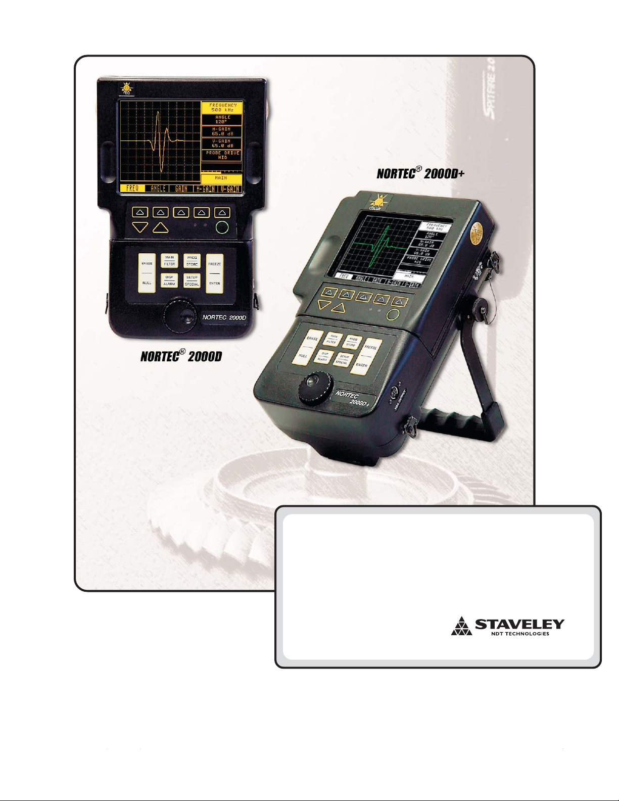
Nortec®2000D Operation Manual
Rev 6 (3/2005) ix
Table of Contents
1.0 Nortec®2000D Preparation for Operation....................................................................... 1
1.1 Unpacking the Nortec® 2000D ......................................................................................................................... 2
1.2 Nortec®2000D/D+ Optional Accessories ........................................................................................................ 2
1.3 Initial Inspection Checklist ............................................................................................................................... 3
1.4 Power Requirements ....................................................................................................................................... 4
1.5 Ni-MH Battery Characteristics ......................................................................................................................... 6
1.6 Li-Ion Battery Pack Characteristics
1.7 Charging the Ni-MH/Li-Ion Battery Pack ......................................................................................................... 7
1.7.1 UBC Specifications .............................................................................................................................. 7
1.7.2 Charger Status Indicators .................................................................................................................... 7
1.7.3 Charger Operation Instructions ........................................................................................................... 8
1.7.4 Battery Safety ...................................................................................................................................... 8
1.7.5 Battery Characteristics ........................................................................................................................ 9
1.7.6 UBC Spare Parts ................................................................................................................................. 9
1.8 Operating Environment.................................................................................................................................... 10
2.0 Nortec®2000D Technical Data ......................................................................................... 11
2.1 Nortec®2000D Technical Specifications ............................................................................................. 12
Basic Performance .......................................................................................................................... 12
Basic Performance (cont’d) ............................................................................................................. 13
Inputs / Outputs ............................................................................................................................... 14
Additional Features.......................................................................................................................... 14
General ............................................................................................................................................ 15
3.0 Nortec®2000D Control Descriptions............................................................................... 17
Instrument Controls ......................................................................................................................................... 18
3.1 Power Button ................................................................................................................................................... 19
3.2 Soft Keys.......................................................................................................................................................... 19
3.3 INC/DEC Arrow Keys ....................................................................................................................................... 19
3.4 LCD/EL Display................................................................................................................................................ 19
3.4.1 EL Hi-Brite Display............................................................................................................................... 21
3.5 SmartKnob™ ................................................................................................................................................... 22
3.6 Immediate Execution Keys .............................................................................................................................. 22
3.7 Function Keys .................................................................................................................................................. 22
3.7.1 Menu Tree .......................................................................................................................................... 24
3.8 Basic Functions ............................................................................................................................................... 25
3.9 Alarm Operation............................................................................................................................................... 29
3.9.1 Box Alarm............................................................................................................................................ 30
3.9.2 Polar Alarm .......................................................................................................................................... 31
3.9.3 Sweep Alarm ........................................................................................................................................ 32
3.10 Dual Frequency Mode...................................................................................................................................... 34
3.11 Program Storage.............................................................................................................................................. 37
3.12 Data Storage .................................................................................................................................................... 40
3.13 Setup Menu...................................................................................................................................................... 45
3.14 Special Functions............................................................................................................................................. 53
3.15 Waterfall Display Function ............................................................................................................................... 54
3.16 Conductivity Mode ........................................................................................................................................... 56
3.16.1 Conductivity Calibration ....................................................................................................................... 58
3.16.2 Conductivity Alarm Menu ..................................................................................................................... 59
3.16.3 Liftoff Alarm Menu ................................................................................................................................ 60
4.0 Nortec®2000D Applications............................................................................................. 61
4.1 Impedance Plane Display-Conductivity Curve ................................................................................................ 62
4.2 Surface Flaw Detection.................................................................................................................................... 64
4.3 Second Layer Crack Detection........................................................................................................................ 66
4.4 Thickness Measurement ................................................................................................................................. 68
4.5 Conductivity — Sorting .................................................................................................................................... 71
4.6 Conductivity — Liftoff Measurement (Paint Layer Thickness Measurement)................................................ 73
4.7 Corrosion Detection with Dual Frequency....................................................................................................... 75
4.8 Scanner Operation........................................................................................................................................... 80
4.9 Waterfall Display Functions ............................................................................................................................. 81