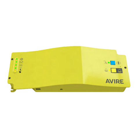
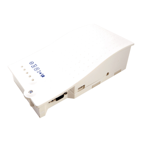
AVIRE 4G DCP User manual

1
4G DCP
Digital Communication Platform
Installation Guide
Ref No MU7756XAV10A-ML Version 1
Part numbers:
4G Single SIM card (RS232): AC-4CM10-610-F-20-000
4G Dual SIM card (RS232): AC-4CM10-810-F-20-000
In the Box
+ 4G DCP - either single or dual version
+ Antenna
+ P-5 H-2V connector (x1)
+ P-3.5 H-4V connector (x1)
+ P-10 H-2V connector (x1)
+ Screw POZ 4.5x35 (x2)
+ Grey clamp (x2)
+ Manual
Single SIM card (RS422/485): AC-4CM10-710-F-40-000
Dual SIM card (RS422/485): AC-4CM10-910-F-40-000
Not Included
+ Screwdriver
+ SIM card(s)
PRODUCT DESCRIPTION
The Digital Communications Platform (DCP) provides an information gateway between
all compatible connected Avire devices in the lift shaft and our online monitoring
platform the Avire Hub. The product is installed as a stand-alone device and doesn’t
require connection to the controller panel.
Dual SIM card DCP version: A dual SIM card version allows switching from one SIM to
another in case the connection is lost. The dual SIM card version also allows the use of
one SIM card for voice and the other one for data only.
*Congure your DCP using the Avire App

2
ELEVATOR SAFETY
Please follow all Health and Safety rules and take all necessary precautions before
and during installation.
IMPORTANT - This device must be installed by qualied personnel and always in a
restricted area where only such personnel have access. All input and output circuits
of the device are classied as ES2 and cannot be accessible to any end user or
connected to any ES1 or SELV circuit.
SETTING UP THE DCP
Avire SIM cards come activated and ready to be installed. If a non-Avire SIM card is
used, please make sure that the SIM card is activated and unlocked.
3. Connect the antenna on the DCP to J2 and
ensure it is completely tightened.
NOTE: Only use antennas authorised by Avire.
4. Connect the battery to J3.
5. Wait for the LEDs to turn on. Once the LEDs
turn on, the SIM card will begin to register
with the network which can take 2-5mins.
Having allowed time for the SIM to register,
check the SIM LED to make sure it is green
or amber (check step 10). If it’s ashing red
check it’s been inserted correctly and then
unlock the SIM card using instructions on
page 5.
6. Check the signal strength by using the built-in network
signal strength scanner. To use the signal scanner
function:
+Turn SW1 dipswitch 1 to ON (check dipswitch 4 is also ON)
Please refer to pages 13 and 14 for the full picture and connector information
1. Open the DCP with a PZ1 screwdriver.
2. Depending on the version of the DCP insert SIM(s) into J4, pushing the SIM(s) until it
(they) click(s). The Dual SIM card version will still work with only 1 SIM installed.
SIM1
J4
J2
J3
J4
Single SIM card
Dual SIM card
SW1
SIM0
SIM0

3
+LEDs on the front of the DCP unit will show the network signal level
+
+
+
+
+
+
+
+
+
+
You can check the status of the power supply, battery, connection, coverage or
Phone Line (SLIC) at any time by referring to the LED Indicators (page 15).
7. With the power supply turned o, connect the positive and negative wires to the
removable plug on connector J6, and then insert the plug into the base of the
circuit.
Note: The signal scanner will
indicate the best location for the
device to receive signal, Network
coverage will vary based on local
conditions.
+Once nished turn SW1 dipswitch 1 back to OFF.
Neutral
Live
SW1
J6
IMPORTANT - The device must be connected to a circuit protected by a circuit
breaker so that both the positive and the neutral that supply the equipment can
be disconnected. To avoid accidents, the circuit breaker must be turned o before
handling the power cables.
Voltage range is 100-240 V A.C. 50-60Hz

4
8. Clamp the power cable using the grey clamp provided inside the box.
9. Place the lid back on the top of the DCP and fasten the lid with the screw.
10. Turn on the power to the DCP. The RUN LED on the DCP should change colour
from ashing amber to ashing green when the mains power connection is made.
If you see any other colour, please consult the LED Indication list on page 15.
RUN LED ashes green Power supply is OK
BAT LED is always on Battery is OK
SIM LED is green or amber Device is connected to the network
Coverage LED is green or amber Good coverage
SLIC LED is green Device is in standby
J6
11. To x the device in position, drill two holes in the wall and insert the plugs and
screws (POZ 4.5x35) provided with the device. Hang the DCP on these two points
using the tear-shaped holes at the back box of the DCP (mid points of holes are
105mm apart).
12. If a non-Avire SIM card is used, APN settings must be set prior to conguring it on
the Avire Hub; please refer to “Setting Parameters on non-Avire SIM cards” (page
6). If the SIM LED is ashing red, please see “SIM Card unlocking” (see page 5).
105mm

5
SIM CARD UNLOCKING
Important Note: An Avire SIM card doesn’t have a SIM PIN code; if the SIM LED is
ashing red, please make sure that the SIM card has been inserted correctly. The SIM
PIN code for other network providers may vary and it can usually be
found on the outer plastic case of the SIM card.
OPTION 1
Disable the blocking PIN code using a conventional mobile phone. Plug the SIM into a
dierent mobile device and delete SIM PIN code in the device settings.
OPTION 2
You can program the PIN code of the SIM card into the DCP using an analogue phone
plugged into to the J1A or J9 connection (please see page 13 for more details).
Single SIM card version:
Enter DCP conguration mode: wait for DCP voice command
Enter SIM card PIN parameter:
xxxx is the SIM PIN code given by the service provider for SIM0.
Dual SIM card version:
Enter DCP conguration mode: wait for DCP voice command
Enter SIM card PIN parameter:
xxxx is the SIM PIN code given by the service provider for SIM0
yyyy is the SIM PIN code for SIM1 (if installed and required).
Example if only 1 SIM PIN code is required:
If SIM0 PIN is needed - *1# xxxx#
If SIM1 PIN is needed please remove PIN code from SIM1 or install SIM into SIM0 port.
At this point, the SIM card LED (middle LED) will stop ashing red. If it does not, make
sure the SIM is correctly inserted and you have entered the correct PIN.
Important Note: Check ADDITIONAL INFORMATION FOR PROGRAMMING THE DCP
on page 12 for more information.

6
CONFIGURING THE DCP
Avire App
The Avire App (available on Apple App store and Google play) allows installers to
quickly and intuitively setup/congure the DCP and connect to the Avire Hub. The Avire
App removes the need for conguration using SMS and instead walks you through the
connection process on your smart phone. The App is available at the links below:
Digit 1 Digit 2 Digit 3 Digit 4
Continent SIM0 Network Type of connection SIM1 Network
The Digital Communications Platform comes pre-congured with factory settings of 0000 (this
conguration doesn’t specify any use case or country).
P091 Digit 1 Digit 2 Digit 3 Digit 4
Country SIM0 Network Type of Connection SIM1 Network
Single Sim 4 = (UK) 3 = (EE) 1 = (Avire HUB) 0 = (No SIM)
Dual Sim 4 = (UK) 3 = (EE) 1 = (Avire HUB) 2 = (O2)
SMS Setup
Parameter 91 (P091) allows quick and easy conguration of APN settings, depending on
the country and network provider. Congure settings for the DCP based on the tables
below by texting the DCP using P091.
Example
2

7
0
Digit 1 0 1-6 7 8
Continent Default Europe Americas Australasia
Digit 2 & 4 1 2 3 4 5 6
Country Spain Portugal Italy UK Germany France
0default default default default default default
1AvireSim AvireSim AvireSim AvireSim AvireSim AvireSim
2Telefonica MEO Wind O2 Telekom DE Orange
3Orange NOS TIM EE ABD SFR
4Vodafone Vodafone Vodafone Vodafone Vodafone DE Bouygues Telecom
5Iliad 3 O2 DE Free Mobile
6tre(3) Virgin BASE
71P Swisscom
8Telit Telit Telit BT A1 Telit
9GiGa tmobileAT
Digit 3 0 1 2 3
Type Transparent Gateway Avire Hub P100 P100 + Avire Hub
Transparent Gateway Enables DCP to provide data/cellular connection to a
device which is connected to it. This setting is often used
when connecting the DCP to a non-avire PSTN phone or
to a lift controller.
Avire Hub Avire Hub setting is used when the intention is to monitor
your *devices using the Avire Hub
P100 P100 setting allows connection to devices utilising the
P100 protocol without connection to the Avire Hub
P100 + Hub P100 + Hub allows connection to devices utilising P100
protocol and monitoring of devices through the Avire Hub
If your SIM’s APN details are not listed on the previous tables, you will need to obtain
this information and then manually programme the details using Parameters 60, 61 &
62. Further details on these settings can be found using this link.
*Avire Ecosystem devices only
go.avire-global.com/DCP

8
OBTAINING THE CCID NUMBER
AVIRE SIM CARDS
Avire SIM cards come unlocked to be used with our products
immediately after plugging them in and setting correct Super settings.
You will need to know the CCID number to add this information to the
Avire Hub.
The CCID Number is shown on the back of the SIM card and also on the outer plastic
case of the SIM card (highlighted in red on the picture below).
Important Note: The CCID number consists of 19 digits.
NON-AVIRE SIM CARDS
It is also possible to retrieve the CCID number by sending a SMS command to a SIM
card telephone number; the command needs to be separated by a comma as shown
below:
Pin1234, P005?
You will receive a text with the CCID number back within a few minutes; in this example,
the number shown after “P005=” is the CCID number of this SIM card.
Important note: Example CCID number is highlighted in red on picture above.
You will need to retrieve the CCID number when the DCP installation is set up on the
Avire Hub online platform. Please ensure that the person conguring the DCP on the
Avire Hub has both the CCID and detail relating to location of the DCP to ensure proper
setup.

9
AVIRE HUB
Please contact your local sales oce for access to the Avire Hub.
The link to the Avire Hub is https://avirehub.avire-global.com
To view installation tutorial videos please go to the “Help” section of the Avire Hub.
Click on “Installations” in the menu on the side
and then on “Buildings”. Inside of “Buildings” tab
click on “Create Building”
Enter information relevant to your installation in General data

10
On the other side of the page please enter the number of elevator group you have in
this installation and how many elevators you have in the group. As an example, if this
is a simplex installation the number of elevator groups will be “1” and the number of
elevators will also be “1”. If it’s a duplex installation it will be “1” and “2” respectively.
You can also edit the group names to easily identify installations. Once all information
is entered click “Next”.
In the new page, you should be able to see Groups and Elevators. Click on “Add
Gateway” under “Gateway” tab and select “DCP 4G”. A pop up window will appear
where you can enter the SIM information (Note: Avire SIMs are (+31), but this doesn’t
aect costs). Enter all required information and then click “Apply”.
Note: The Background Call Period is the frequency of test checks and 72hrs is the
maximum period as per guidance from standards.

11
Click “Save” in the left corner under the General data column.
To make sure that everything has been set up correctly click on the green DCP button.
The buttons “Access” and “Events” should now be accessible.
Click on the “Access” button.
Please click on the “Read Parameters” button. On the right hand side of the page you
will see a window with time, date and the word “Connecting” shown in green. Once
the DCP is connected to the Avire Hub parameters will appear. This means your DCP is
ready to be connected to emergency phones and other products within our Ecosystem.

12
ADDITIONAL INFORMATION FOR PROGRAMMING THE DCP
SMS COMMANDS
+All DCP parameters can be remotely congured via SMS sent to the SIM card’s number.
+Each SMS message should begin with ‘Pin1234’ which is the access code to read or make any changes to the
conguration of the DCP.
+You can modify or check several parameters in each SMS by separating them with commas ","
To send parameter information:
Text Description
Pin1234, Pzzz xxx (send) • Pin1234 is default PIN code for DCP
• Pzzz is the programming command
• xxx is the parameter
To read parameter information:
Text Description
PinXXXX, Pzzz? (send) • Pin1234 is default PIN code for DCP
• Pzzz is the programming command
• “?” is to request a parameter read
Note: Use a question mark ‘?’ when you are reading parameters.
Examples:
1. To program telephone number 1 in the DCP when connected to a DAU
E.g: Pin1234, P031 0123456789 (send, text message will come back with P031=0123456789)
2. To retrieve telephone number 1 in the DCP when connected to a DAU
E.g: Pin1234, P031? (send, text message will come back with P031= or with the programmed number)
CMD Description Default value
P005 CCID- Unique Identier of the Sim Card Country dependent
P020
DCP Background Call Mode
P020=00 -> Transparent Protocol
P020=06 -> CAN Protocol
P020=21 -> P100 Protocol
21 (Autodialler’s need to make Background calls in
P100 Protocol)
P064 Background Call Periodicity (in Minutes) 4320 (3 days)
P030 Maintenance Alarm Number (Blank)
P031 Alarm Number 1 (Blank – Insert your alarm number here)
P032 Alarm Number 2 (Blank)
P033 Alarm Number 3 (Blank)
P034 Alarm Number 4 (Blank)
P035 Background Number (not used with DAU) 3308084431 (must match Background Number in
Autodialler, without prexes)
P008 Enable Guidance Message * 0 (disabled)
P085 Language 1 - Spanish, 2 - Portuguese, 3 - Italian, 4 - English,
5 - German, 6 - French
P091 Super settings set up 0000
P003 DCP information (software version, type of DCP) As per package
P051 Dual SIM settings 0
Important Note: The default PIN code for DCP is always 1234.
Parameter P051 - Dual SIM card version:
0 SIM0 acting as a primary SIM card. In case of failure of primary SIM, it will switch to SIM1.
1 SIM1 acting as a primary SIM card. In case of failure of primary SIM, it will switch to SIM0.
2SIM0 - Voice SIM, SIM1 - Data SIM. SIM1 is attahed to network, listening to any incoming calls, once an alarm call
is active, the DCP will switch to SIM0 and stay active till the end of alarm.

13
Connector Description
Description
J2 External antenna
J3 Battery
J6 Power Supply
J8 CANBus
J9/ J1A Phone line
J10 Serial connector
J11 Programmable I/O
To access dipswitches and connectors,
open the DCP case by unfastening the
front screw (using a PZ1 screwdriver) and
removing the lid.
J2 - External antenna - Connect the external antenna delivered with the kit to the
J2 connector. Only antennas approved by Avire should be used in the installation,
otherwise the device might not function properly and may be damaged.
J3 - Battery
Pin Function Signal
1+12 Positive
2GND Negative
J6 - Power Supply
Pin Function Signal
1LLive
2N Neutral
J8 - CANBus
Pin Function Signal
1VCC Unregulated
output
2CANH Bus CAN H
3CANL Bus CAN L
4GND Ground
J9/ J1A - Phone line (SLIC)
Pin Function Signal
1L1 Tip
2L2 Ring
Supply voltage: 100-240 VAC, 50/60 Hz
VCC is an unregulated output 10-21 VDC + battery
support 10-14 VDC

14
J10 CONNECTOR - RS-232 or 422/485 Serial Connector
The J10 connector is a standard serial communication port that allows the connection
of computers, controls or any other device that needs remote communication through
a reliable wireless data channel. The connectivity provided by the port is in real time
and acts as a point to point transmitter.
Pin Signal Pin Signal
2TX Out 7RTS Out
3RX In 8CTS In
5Ground Ground RS-232
Pin Signal Pin Signal
2T+ T+ RS422 7T- T- RS422
3R- R- RS422 8R+ R+ RS422
5Ground Ground RS-422
J11 - Digital Input/ Output
Pin Function Signal
1AK1 Input Outo-
Coupler
2AK2 Input Outo-
Coupler
3VCC Output 10-21
VDC
4OP1 Open collector
Mosfet N
5GND Ground
SW1 Function Description
1 Signal tester Inbuilt signal tester
Default OFF
2Not used Not used
3
Reserved Avire internal use only
Default OFF
4
CAN Ω
Activates the CANBus End of Line (EOL) for the CAN
connector.
Default ON – DCP is typically an End of Line device.

15
LED INDICATORS
The DCP has ve indicator LEDs that constantly report the device status. The indicators
will be either red, amber or green.
Each indicator will be fully on, fully o or ashing. On start-up, you should see the
following within 2- 5 minutes (this will vary):
RUN LED ashes in green. Power supply is OK
BAT LED is always on Battery is OK
SIM LED is green or amber Device is connected to the network
Coverage LED is green or amber Good coverage
SLIC LED is green Device is in standby
RUN LED
OFF
ON FLASHING
Green Amber Red Green Amber Red
CRITICAL SYSTEM ERROR
Proper
Operation (AC)
Proper
Operation
(BAT)
Restarting
System
BATTERY
OFF
ON FLASHING
Green Amber Red Orange Red
OK Charging Low DAU battery failure Error
SIM OFF ON FLASHING
Green Amber Red Green Amber Red
AT
modem
Available
GSM and
GPRS
GSM
available
GPRS not
available
Out of
Service /
Initialising
Ongoing Data
Transmission
Ongoing
voice call
Sim error or
missing pin
Amber/Red Missing PUK
SLIC
OFF
ON FLASHING
Green Amber Red Green
RS-232 local
conguration
Local line
ready
Initialising
local line
Local line
out of
service
Local line in use
COVERAGE
OFF
ON
Green Amber Red
AT
modem OK Medium Low
The below tables provides an overview for what each LED colour means:
Important Note: DCP shows battery status of DCP or battery failure of any attached DAU
units as per EN81-28:2018.

16
SYSTEM ARCHITECTURES
DCP 2 button
Triphony Unit
Universal Power
Supply
LPBus Digital
Audio Unit
Induction Loop CAN Bus Splitter
PIT Phone
Lift car system architecture with DCP, LPBus
DAU, TOC Triphony Unit and Inductive Loop

17
Two lift cars with DCP, UPS, CANBus Splitter,
TOC Triphony Unit, LPBus DAU, PIT Phone and
Inductive Loops
Four lift cars with DCP, UPS, CANBus
Splitters, LPBus DAU, Triphony Units
TOC, PIT Phones and Inductive
Loops
Two lift car system architecture with DCP,
LPBus DAU, TOC and BOC Triphony Units and
Inductive Loops
Notes:
UPS battery back up
only uses H and L
wires from DCP.
There is a maximum of
two CANBus Splitters
per DCP.

18
Installation with a Digital Audio Unit
When connecting a Digital Audio Unit (DAU) connect the unit or the CAN Bus Splitter to
J8 using a 4-core cable (2 wires for power and 2 for communication)
+If only connecting 1 device to the DCP (e.g. DAU) set SW1 dipswitch 4 to ON
+It is recommended to use shielded twisted pair cables
+If connecting 2 devices to the DCP (e.g. 1 DAU and 1 PIT unit) set SW1 dipswitch 4 to OFF
+There are no standard wiring colours for CANBus wiring
Please refer to the DAU Installation guide for full setup of the DAU.
J8 CAN BUS
1 +Vin
2 CAN H
3 CAN L
4 -Vin
1
4
-Vin
L
H
+Vin

19
Installation with a Memcom+
When connecting a Memcom+ use the analogue phone line connection from J1A or J9.
Please refer to the Memcom+ installation guide for full set up of the Memcom+.
J 9 G S M
phone line
OUT
N
L
Connections on DCP
J 9 G S M
phone
line IN
Connection on Memcom +

4G DCP IG_ V01 (ML): PC 10/07/20
ENVIRONMENT CONDITIONS
This device is designed to be used indoors (0oC to 45oC with relative humidity between
20% to 80% not condensing). Sudden changes of temperature and humidity should be
avoided.
CLEANING AND MAINTENANCE
Use a soft dry cloth. Do not use solvent or abrasive products.
SAFETY
Please read these safety instructions before starting the device.
+Do not expose this device to liquids or excessive humidity. The DCP is an indoor device and
is not waterproof.
+Do not expose the device to re.
+Do not try to modify the device.
+Do not use the device in potentially hazardous areas or where there is risk of explosion.
The DCP emits low levels of radio frequency when in operation.
BATTERY
The DCP includes a NiCd 12 V/600 mAh battery that allows it to keep functioning in the
event of a mains power failure.
This battery should be replaced every 3 years. Only install batteries authorized by Avire,
and only allow qualied personnel to replace the battery.
This battery should be properly recycled and not disposed of with unsorted household
waste. Please take all necessary precautions when changing the battery.
DISPOSAL
The device complies with regulations 2002/95/CE and 2003/108/CE regarding
the use and disposal of hazardous substances in electric appliances.
Do not dispose of this device with unsorted household waste. Disposing
of the device in an unauthorised way could result in a ne in line with local
regulations.
ENVIRONMENTAL REGULATIONS
RoHS - Avire certies that its production process complies with the 2011/65/EU
European Directive of 03 January 2013 regarding the restriction of use of hazardous
substances in electric and electronic appliances.
INSTALLATION
The equipment is intended for installation in restricted areas by qualied personnel.
GENERAL NOTE
Any wiring or plug used together with the equipment must be certied in line with
relevant product standards. The wiring insulation must comply with the applicable IEC
60332 or IEC 60695/11/21 standards.
Avire Trading Ltd
Unit 1, The Switchback
Gardner Road
Maidenhead
Berkshire
SL6 7RJ, UK
T: 01628 540100
F: 01628 621 947
E: sales.uk@avire-global.com
W: www.avire-global.com
This manual suits for next models
4
Table of contents
Languages:
Other AVIRE Conference System manuals
Popular Conference System manuals by other brands

CommScope
CommScope OneCell RP Series Installation

Sailor
Sailor C4951WP Operating and installation instructions

Albrecht
Albrecht AE 600 S operating manual

Cambium Networks
Cambium Networks PTP 820E Quick installation instructions

Kraydel
Kraydel Konnect user guide

iPECS
iPECS eMG100 Hardware description & installation manual