Riedel ARIST M User manual

General
Artist m is known for its simple installation and putting into operation. If you still need support or technical
assistance, please contact RIEDEL – The Communications People.
We are always happy to help you with any questions you might have.
RIEDEL – Communications GmbH
Rudower Chaussee 3 / R1
12489 Berlin
Germany
Tel. +49-(0)30 678261-0
Fax +49-(0)30 678261-59
www.riedel.net
Copyright 2000 RIEDEL Funk- und Intercomtechnik Thomas Riedel – Wuppertal / Deutschland

ARTIST m – Instalation Guide 2.3 – 12.06.2003 3
Table of Contents
INTRODUCTION
ARTIST m – Digital Matrix Intercom ................................................. 4
CONTROL PANELS
Panel Types........................................................................................... 5
Connections: Control Panel Rear View............................................. 6
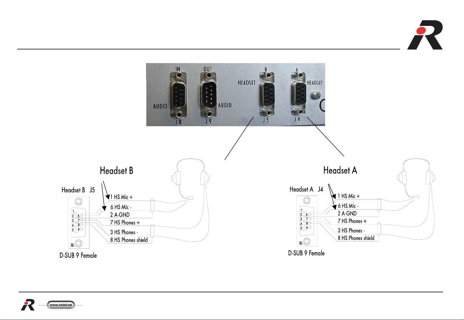
Headset connection on the front of the unit..................................... 7
Headset connection on the rear of the unit...................................... 8
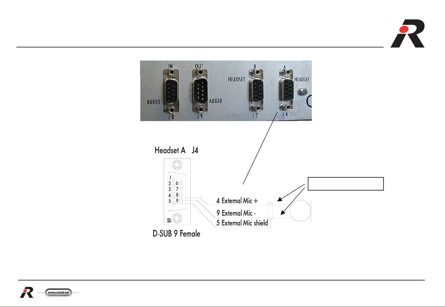
Connection of an external microphon............................................... 9
Connection of an external loudspeaker........................................... 10
Connection to GPI Input / Output Contacts .................................... 11
Connection of external analog audio sources................................. 12
Control Panel including Audio and GPI Options............................ 13
CONNECTIONS OF PANELS TO MATRIX
Connection of a Panel via CAT5 ...................................................... 14
Connection of a Panel via Coax ....................................................... 15
Connection of an Expansion Panel.................................................... 16
ARTIST M CUSTOM PANEL INTERFACE RIF 2064
Front and Rear View RIF 2064 ......................................................... 17
Connector Pin Assignment RIF 2064 ............................................... 18
Connection to GPI Input/Output Contacts RIF 2064 ..................... 19
Connection of Audio Input / Output RIF 2064 ............................... 20
Connecting a RIF2064 via CAT5 to a ARTIST M Matrix .............. 21
MATRIX
Rear view Matrix.. ............................................................................... 22
Alarm Contacts.. .................................................................................. 23
Serial Interface Connection................................................................. 24
Fiber Connection Up / Downstream.................................................. 25
Ethernet Connection 10/100BT ........................................................ 26
Connection of GPI Input / Output ..................................................... 27
PIN ASSIGNMENTS
Control Panel 19“ RCP10xx .............................................................. 28
Expansion Panel .................................................................................. 29
Desktop Panel.... .................................................................................. 30
Matrix 1/2: CPU - and Client Card/s .............................................. 31
Matrix 2/2: GPI Input / - Output ........................................................ 32
PANEL QUICK GUIDE
Funktions ............................................................................................... 33
Funktion Keys............ ........................................................................... 34
OPT Key ............................................................................................... 35
TECHNICAL SPECIFICATIONS
Control Panel / Matrix ......................................................................... 36

ARTIST m – Instalation Guide 2.3 – 12.06.2003 4
ARTIST m - Digital Matrix Intercom

ARTIST m – Instalation Guide 2.3 – 12.06.2003 5
ARTIST m Control Panel Types
Expansion Control Panel
ECP1016E
Rackmount Control Panels
RCP1012E
RCP1028E
Desktop Control Panel
DCP1016E

ARTIST m – Instalation Guide 2.3 – 12.06.2003 6
Connections: Control Panel Rear View
J10 Unicom
(optional)
J1 Matrix connection via CAT5
J2 Matrix connection via Coax
J7 GPI Out 1) J8 Audio In 2)
J6 GPI In 1)
h
J9 Audio Out 2)
J5 Headset B 2)
J3 Expansion J4 Headset A 2)
1) requires GPI-Option RCP-GPI-E
2) requires Audio-Option RCP-AIO-E

ARTIST m – Instalation Guide 2.3 – 12.06.2003 7
Headset connection on the front of the unit
Front view of the connectors
(+ 5V A/B power )

ARTIST m – Instalation Guide 2.3 – 12.06.2003 8
Headset connection on the rear of the panel
Front view of the connectors
+ 5V Phantom Power + 5V Phantom Power
By unsymmetrical connection of a electrec
microphone the micro + is on PIN 1 and micro
shield is switched to PIN 6 and PIN 2. This results
in A/B power for the electret microphone.
requires Audio-Option RCP-AIO-E

ARTIST m – Instalation Guide 2.3 – 12.06.2003 9
Connection of an external microphone to the
rear of the Conrol Panel
Front view of the connectors
+ 5V Phantom Power
By unsymmetrical connection of a electrec
microphone the micro + is on PIN 4 and micro
shield is switched to PIN 9 and PIN 5. This results
in A/B power for the electret microphone.
requires Audio-Option RCP-AIO-E

ARTIST m – Instalation Guide 2.3 – 12.06.2003 10
Connection of a Loudspeaker to the rear of
the panel
Front view of the connectors
Output wattage:
2 W /4 Ohm
requires Audio-Option RCP-AIO-E

ARTIST m – Instalation Guide 2.3 – 12.06.2003 11
Connection to GPI Input / Output Contacts
Eg. External 5V relays
Eg. external contacts
4 +5V
*
4 +5V
*
Notes:
•The carrying capacity of Pin 4 totals 50 mA
•The contact carrying capacity of the outputs is 300 mA
(protected by self resetting fuse)
•The voltage on the GPI Inputs totals 5 - 48 V
•The bond strength for GPI Output is max. 60V
•* n.c. = not Connected
Front view of the connectors
requires GPI-Option RCP-GPI-E

ARTIST m – Instalation Guide 2.3 – 12.06.2003 12
Connection of external analog audio sources
Level: norm +6dBu maximal +18dBu
Input Impedance: >20kOhm
Level: normal +6dBu maximal +18dBu
Output Impedance: < 10Ohm
Front view of the connectors requires Audio-Option RCP-AIO-E

ARTIST m – Instalation Guide 2.3 – 12.06.2003 13
Control Panel including Audio and GPI Option

ARTIST m – Instalation Guide 2.3 – 12.06.2003 14
Connection of a Panel via CAT5 to an
ARTIST m Matrix
Cable Specifications
•Type: Cat5 (4x2 AWG24)
Twisted pair with overall braid
screen
•Connectors: RJ 45
•Cable Length: max. 300 meters
Rear view: ARTIST m Frame
Pin Connections
Rear view: Control Panel, here a RCP-1028

ARTIST m – Instalation Guide 2.3 – 12.06.2003 15
Connection of a Panel via Coax to an
ARTIST m Matrix
Rear view: ARTIST m Frame
Cable Specificaitons
•Type: RG59 – 20 AWG
Video Kabel
75 Ω/ 0,8 / 3,7
FRNC – halogen free
•Cable Length: max. 650 Meter
•Type 75 Ω/ 0,6 / 3,7
•Cable Length: max. 350 Meter
•Connectors: BNC 75 Ω
(anti-kink)
Rear view: Control Panel, here a RCP-1028

ARTIST m – Instalation Guide 2.3 – 12.06.2003 16
Connection of an Expansion Panels
Rackmount Panel, here a RCP1028E
Expansion Panel Adresse 1
Cable Specifications
•Type: Cat5 (4x2 AWG24)
Twisted pair with overall braid
screen
•Connector: RJ 45
•Cable Length: max. 2 Meter
Expansion Panel –1, ECP1016E
Expansion Panel –2, ECP1016E
Expansion Panel Adresse 2
max. 7x Expansion Panels
Expansion Panel –n, ECP1016E
Expansion Panel Adresse n
Note: Only use each address once!

ARTIST m – Instalation Guide 2.3 – 12.06.2003 17
Front and Rear View RIF 2064
RIF 2064 Front View
RIF 2064 Rear View

ARTIST m – Instalation Guide 2.3 – 12.06.2003 18
Connector Pin Assignment
RIF 2064
Pin Signal
1GPI1In+
2GPI2In+
3GPI3In+
45V
5n.c.
6GPI1In—
7GPI2In—
8GPI3In—
9
G
ND
Pin Signal
1GPI1OutA
2GPI2OutA
3GPI3OutA
45V
5n.c.
6GPI1OutB
7GPI2OutB
8GPI3OutB
9
G
ND
"GPI-Output" *
D-Sub 9 Male
„GPI-Input“ *
D-Sub 9 Female
Note:
a) Maximum load of Pin 4 is 50 mA (fused)
b) Maximum load of GPI-Output is 300 mA each (fused)
c) GPI-Input Range: +5 ... +48 V
Pin Signal
1TxD+
2TxD—
3RxD+
45VOut
55VOut
6RxD—
7GND
8GND
"Mainframe"
RJ45
Pin Signal
1Shield
2OUT+
3OUT-
"Audio Out"
3 pol XLR Male
Pin Signal
1Shield
2IN+
3IN-
"Audio IN"
3 pol XLR Female
+5V
1
2
3
4
5
6
7
8
9
10
11
12
13
14
15
16
17
18
19
20
21
22
23
24
25
26
27
28
29
30
31
32
33
34
35
36
37
Pin Funktion
IN 1
IN 2
IN 3
IN 4
IN 5
IN 6
IN 7
IN 8
IN 9
IN 10
IN 11
IN 12
IN 13
IN 14
IN 15
IN 16
GND
GND
OUT1
OUT2
OUT3
OUT4
OUT5
OUT6
OUT7
OUT8
OUT9
OUT10
OUT11
OUT12
OUT13
OUT14
OUT15
OUT16
recovery diode
GND
recovery diode
500mA/24V
500mA/24V
OUT 1
500mA/24V
500mA/24V
OUT 8
OUT 9
OUT 16
IN 1
+5V
IN 16

ARTIST m – Instalation Guide 2.3 – 12.06.2003 19
Connection to GPI Input/Output Contacts
RIF 2064
Eg. External 5V relay
Eg. external contacts
4 +5V
*
4 +5V
*
Front view of the connectors

ARTIST m – Instalation Guide 2.3 – 12.06.2003 20
Connection of Audio Input / Output
RIF 2064
1
2
3
2 Audio Out +
3 Audio Out -
2
1
33 Audio In -
2 Audio In +
1 Shield
1 Shield
XLR 3 Male XLR 3 Female
Level: nominal +6dBu maximal +18dBu
Output impedance: < 10 Ohm
Level: nominal +6dBu maximal +18dBu
Input impedance: >20k Ohm
Table of contents
Other Riedel Conference System manuals