AVIRE DCP User manual

1
DCP WAVE
Digital Communication Platform with integrated Digital Audio Unit
Installation Guide
Ref No: MU-89112AV101V01 GB
Product Part Number:
4G: AC-4CT18-100-0-4L-000
2G: AC-2CT18-100-0-2L-000
The DCP WAVE combines the Digital Communication Platform (DCP) with the Top-of-
Car Digital Audio Unit (TOC DAU) into one device and provides 2-way communication
from inside the car to the top of car. The unit is mounted on the top of lift car and it
does not require connection to the machine room.
You have the possibility to use a microphone in the cabin and to control external 12V
or 24V pictograms. It also allows audio communication with the machine room through
the “Intercom” function.
IN THE BOX
+DCP Wave
+Antenna
+P-5 H-2V connector (Phone
Connector) (x1)
+P-10 H-2V connector (Power
Connector) (x1)
+P-3.5 H-6V connector (Input
connector) (x1) Ext. Siren output cable
wire loom (1m with 3 outputs)
+Grey clamp (x2)
+Screws (x4)
+Box xing Screws (x2)
+Installation Guide
NOT INCLUDED
+Screwdriver
+SIM Card (Avire SIM can be purchased
through sales)
SPECIFICATION: 2G & 4G VERSIONS
DCP WAVE
Input 4G: 100 – 240 VAC mains power
2G: 220 – 240 VAC mains power
Consumption max. 10 VA
Internal Battery 12V, 600 mAh, 9hr
Connections RS232 or RS422/485; CANbus, LPBus
Operating Temp -10ºC to +65ºC
Dimensions 320x116x77mm
Network 2G or 4G available
Note: Before installation pease ensure there is good signal coverage using the inbuilt
signal strength scanner.
Typical System Architecture

2
Connectors
Step 1
Open the DCP Wave device with
a screwdriver
Step 2
Connect the antenna on the
DCP to connector (1) and ensure
it is cmpletely tightened. Only
use antennas authorised by
Avire, other the device might
not work.
Step 6
Check the signal strength by
using the built-in signal strength
scanner. To use the signal
strength scanner function:
1) Turn SW1 dipswitch to ON
2) LEDs will show the network
signal level
3) Once nished, turn SW1 to o
4) Default settings - 1: OFF, 2:
OFF, 3: OFF, 4: ON
Step 3
Insert SIM into connector (2)
pushing the SIM until it clicks
into place. Refer to SIM Card
unlocking section
for details on how
to avtivatre the SIM
Card.
Step 5
Wait for the LED lights to turn
on. Check the SIM LED to make
sure it is green or amber. If it is
ashing red check its
been inserted correctly
and then unlock the
SIM using instructions
in ‘how to unlock the
SIM Card’ section of
the install guide.
Step 4
Connect the battery to
connector (3). This must be
connected to provide battery
backup in an event of a power
faliure.
1 Antenna 6 Serial Port 11 DAU output 16 Firmware DAU
2 Sim Card 7 Phone line 12 DAU inputs 17 DAU
conguration
3 Battery 8 Power supply 13 Ext. microphone 18 RS-232 DAU
4 Firmware DCP 9 Fuse 14 Ext. LED
5 DCP conguration 10 LPBus 15 LED switch
DAUDCP
Avire SIM cards come activated and ready to be installed. If a non-Avire SIM card is
used, please make sure that the SIM card is activated and unlocked; also ensure that
the SIM is compatible with 2G/4G, depending on the DCP WAVE purchased.
Setting up the device - DCP

3
Step 7
Connect the power supply
230VAC to connector (8) using
the 2 pin connector supplied in
the unit. (Power supply wires:
non-polarised connection)
Step 10
Turn on the power to the DCP
Wave. The RUN LED on the
Wave should change colour
from ashing amber to ashing
green when the mains power
connection is made. If you see
any other colour please consult
the LED indication list below.
Step 9
Place the lid back on the top of
the DCP WAVE and fasten the
lid with the screw.
Step 8
Clamp the power cable using
the grey clamp provided inside
the box
You can check the status of the power supply, battery, connection, coverage or Phone
line at any time by referring to the LED indicators.
Run LED ashes in green Power supply is OK
BAT LED is always on Battery is OK
SIM LED is green or amber Device is connected to the network
Coverage LED is green or amber Good coverage
SLIC LED is green Device is in standby
Note: If a non-Avire SIM is used:
• APN settings must be set prior to conguring it on the Avire Hub; please refer to
“Setting Parameters on non-Avire SIM cards”.
• If the SIM LED is ashing red, please see “SIM Card unlocking”.
• Make sure to check with the network provider to ensure the SIM is compatible with
2G/4G, depending on the DCP WAVE device purchased.

4
Setting up the device - DAU
Step 1
If NOT using an external
microphone, disconnect
cable attached to connector
(13) (External microphone
connected at factory).
Step 2
If NOT using external
pictograms, disconnect cable
attached to connector (14)
(External pictograms connected
at factory).
Step 6
Programme the DAU to the
desired usage (pg. 10)
Step 3
Wire the alarm button to the
alarm inputs on the TOC DAU.
(N/O is default)
Step 5
Place the external microphone
and external speaker in a
location that the device can
function properly.
Step 4
Connect the external LED’s
wiring to the pictograms located
on the COP (in the lift).
Step 7
Test functionality is correct
before leaving site.
Basic Programming - DCP/DAU
1. Via SMS:
Pin1234,P031 (customer emergency alarm number)
Conrmation SMS will show on mobile phone:
Mk775: (1234567890) number
P031= (programmed alarm number shown)
2. Using a telephone handset J1A:
Plug in Handset in the DCP (J1A) or wire into J9
Press 0
Enter *#*1234*#* (Passcode)
*031# (telephone number#)
Then hang up handset
(Default: Alarm
acknowledgement message
will be played to the
operator to require them
to press “0”, otherwise
call will be placed again
automatically)
For further information and
programming the DAU – see
page 10
SIM Card Unlocking (Non-Avire SIM)
Important Note: An Avire SIM card does not have a SIM Pin code; if the SIM LED is
ashing red, please make sure that the SIM card has been inserted correctly. The SIM
PIN code for other network providers may vary, and it can usually be found on the
outer plastic case of the SIM card.

5
For non-Avire SIM cards which have a PIN code:
Option 1
Disable the blocking PIN code using a conventional mobile phone. Plug the SIM into a
dierent mobile device and delete SIM PIN code in the device settings.
Option 2
You can program the PIN code of the SIM card into the DCP using an analogue phone
plugged into connector (7).
You can program the PIN code of the SIM card into the DCP using an analogue phone
plugged into to the J1A or J9 connection (please see page 13 for more details).
Single SIM card version:
Enter DCP conguration mode: wait for DCP voice command
Enter SIM card PIN parameter:
xxxx is the SIM PIN code given by the service provider for SIM0.
Dual SIM card version:
Enter DCP conguration mode: wait for DCP voice command
Enter SIM card PIN parameter:
xxxx is the SIM PIN code given by the service provider for SIM0
yyyy is the SIM PIN code for SIM1 (if installed and required).
Example if only 1 SIM PIN code is required:
If SIM0 PIN is needed - *1# xxxx#
If SIM1 PIN is needed please remove PIN code from SIM1 or install SIM into SIM0 port.
At this point, the SIM card LED (middle LED) will stop ashing red. If it does not, make
sure the SIM is correctly inserted and you have entered the correct PIN.

6
SETTING PARAMETERS ON NON AVIRE SIMS
OPTION 1
Super settings allow quick and easy conguration of APN settings, depending on the
country and network provider. Congure settings for the DCP based on the tables
below.
Example:
Digit 1 0 1-6 7 8
Continent Default Europe Americas Australasia
Digit 1 Digit 2 Digit 3 Digit 4
Continent SIM0 Network Type of connection SIM1 Network
The Digital Communications Platform comes pre-congured with factory settings of 0000 (this
conguration doesn’t specify any use case or country).
Digit 2 & 4 1 2 3 4 5 6
Country Spain Portugal Italy UK Germany France
0default default default default default default
1AvireSim AvireSim AvireSim AvireSim AvireSim AvireSim
2Telefonica MEO Wind O2 Telekom DE Orange
3Orange NOS TIM EE ABD SFR
4Vodafone Vodafone Vodafone Vodafone Vodafone DE Bouygues Telecom
5Iliad 3 O2 DE Free Mobile
6tre(3) Virgin BASE
71P Swisscom
8Telit Telit Telit BT A1 Telit
9GiGa tmobileAT
Digit 3 0 1 2 3
Type Transparent Gateway Avire Hub P100 P100 + Avire Hub
Digit 1 Digit 2 Digit 3 Digit 4
Country SIM0 Network Type of Connection SIM1 Network
Single Sim 4 = (UK) 3 = (EE) 1 = (Avire HUB) 0 = (No SIM)
Dual Sim 4 = (UK) 3 = (EE) 1 = (Avire HUB) 2 = (O2)

7
Once all digits are selected, the text
needs to be sent to the SIM card
telephone number along with the
PIN code and command. Response
should show:
0
0
OPTION 2
If super settings are not used, then APN settings need to be set up manually:
Command Description Parameters
P060 (P zero six zero) SIM0 congurations APN name ;APN username ; APN password*
P061 (P zero six one) SIM1 congurations APN name ;APN username ; APN password*
P063 (P zero six three) Type of connection Shared by both SIM cards
* Separated by “;”
These parameters must be congured by sending an SMS to the SIM card number.
Examples for various regional providers are shown below:
Carrier APN name APN username APN password
Vodafone UK wap.vodafone.co.uk wap wap
Telekom DE Telekom (blank) (blank)
Orange France Orange.fr orange orange
Other APN settings are available on the web and can be easily found online. If an APN
is incorrect for the provider or is not set up correctly, the DCP will not check into the
Avire HUB.
Important Note: The default PIN code for DCP is always 1234.
Example of an SMS for single SIM card device (for example if the SIM0 card is from
Vodafone):
Pin1234, P060 wap.vodafone.co.uk ; wap ; wap, P063 1
If either APN username and/or APN password are (blank) (DeutscheTelekom example)
and the DCP is congured to be used with the Avire Hub, then the text message will be:
Pin1234, P060 (blank), P063 1
Example for dual SIM card version with SIM cards
from Vodafone UK (SIM0) and EE UK (SIM1):
Pin1234, P060 wap.vodafone.co.uk ; wap ; wap, P061
everywhere ; eesecure ; secure, P063 1
P063 0 1 2 3
Type Transparent Gateway Avire Hub P100 P100 + Avire Hub
If everything is congured correctly, you will
receive a text within a few minutes:

8
Obtaining the CCID number
AVIRE SIM CARDS
Avire SIM cards come unlocked to be used with our products
immediately after plugging them in and setting correct Super settings.
You will need to know the CCID number to add this information to the
Avire Hub.
The CCID Number is shown on the back of the SIM card and also on the outer plastic
case of the SIM card (highlighted in red on the picture below).
Important Note: The CCID number consists of 19 digits.
NON-AVIRE SIM CARDS
It is also possible to retrieve the CCID number by sending a SMS command to a SIM
card telephone number; the command needs to be separated by a comma as shown
below:
Pin1234, P005?
You will receive a text with the CCID number back within a few minutes; in this example,
the number shown after “P005=” is the CCID number of this SIM card.
Important note: Example CCID number is highlighted in red on picture above.
You will need to retrieve the CCID number when the DCP installation is set up on the
Avire Hub online platform. Please ensure that the person conguring the DCP on the
Avire Hub has both the CCID and detail relating to location of the DCP to ensure proper
setup.

9
SW1 Function Description
1
Signal tester Inbuilt signal tester
Default OFF
2
Not used Not used
3
Reserved Avire internal use only
Default OFF
4
CAN ΩActivates the CANBus End of Line (EOL) for the CAN connector.
Default ON – DCP is typically an End of Line device.
SW1 Function Description
1
Shaft (car)
number
Default OFF, OFF – DAU always in shaft 1 as part of the DCP.
(Function not necessary for DCP WAVE, leave as default)
2
Not used Not used
3
CAN Ω
Activates the CANBus End of Line (EOL) for the CAN connector.
Default ON – DAU is always the End of Line device.
Advanced Congurations
DCP Congurations: Dipswitch (SW1)
DAU Congurations: Dipswitch (17)
Additional Information for Programming the DCP
ADDITIONAL INFORMATION FOR PROGRAMMING THE DCP
+All DCP parameters can be remotely congured via SMS sent to the SIM card’s number.
+Each SMS message should begin with ‘Pin1234’ which is the access code to read or make any changes to the
conguration of the DCP.
+You can modify or check several parameters in each SMS by separating them with commas ","
To send parameter information:
Text Description
Pin1234, Pzzz xxx (send) • Pin1234 is default PIN code for DCP
• Pzzz is the programming command
• xxx is the parameter
To read parameter information:
Text Description
PinXXXX, Pzzz? (send) • Pin1234 is default PIN code for DCP
• Pzzz is the programming command
• “?” is to request a parameter read

10
Note: Use a question mark ‘?’ when you are reading parameters.
Examples:
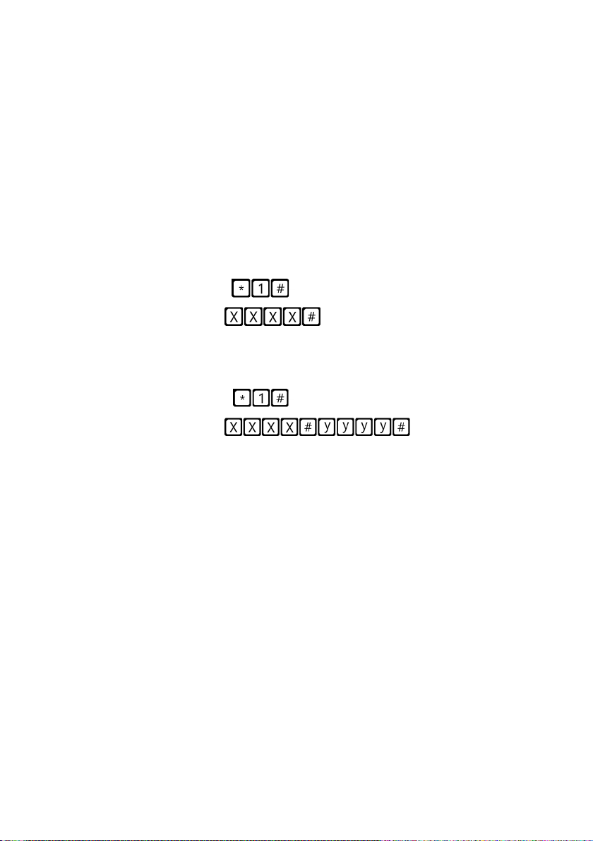
1. To program telephone number 1 in the DCP when connected to a DAU
E.g: Pin1234, P031 0123456789 (send, text message will come back with P031=0123456789)
2. To retrieve telephone number 1 in the DCP when connected to a DAU
E.g: Pin1234, P031? (send, text message will come back with P031= or with the programmed number)
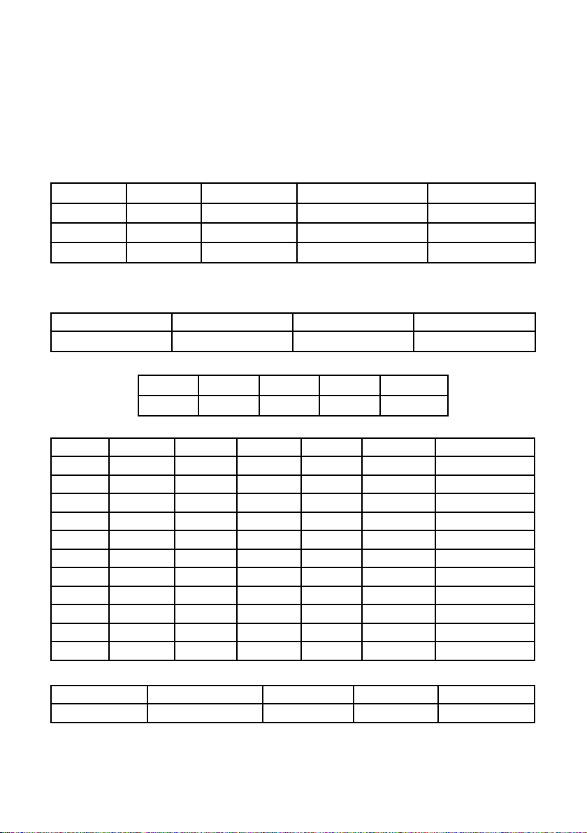
CMD Description Default value
P003 DCP information (software version, type) As per package
P008 Enable Guidance Message 0 (disabled)
P030 Maintenance Alarm Number (Blank)
P031 Alarm Number 1 (Blank)
P032 Alarm Number 2 (Blank)
P033 Alarm Number 3 (Blank)
P034 Alarm Number 4 (Blank)
P064 Background Call Periodicity (in Minutes) 4320 (3 days)
P091 Super settings set up 0000
P051 Dual SIM settings 0 (disabled)
(N/A for DCP WAVE) 0 1 - Spanish, 2 - Portuguese, 3 - Italian, 4 - English,
5 - German, 6 - French
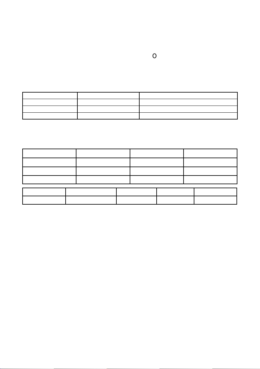
P1170 Alarm Push Polarity (Default N/O) Normally Open (N/O)
DCP information (software version, type of DCP) As per package
P1171 Alarm Push Polarity (change to N/C) N/C
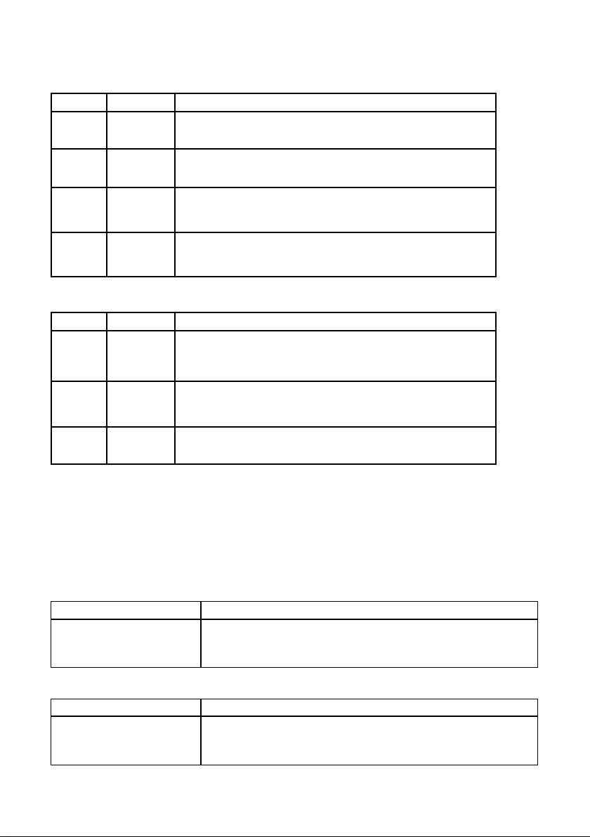
Parameter P051 – Dual SIM card version:
0SIM0 acting as a primary SIM card. In case of failure of primary SIM< it
will switch to SIM1.
1SIM1 acting as a primary SIM card. In case of failure of primary SIM< it
will switch to SIM0.
2
SIM0 – Voice SIM, SIM1 – Data SIM. SIM1 is attached to network,
listening to any incoming calls, once an alarm call is active, the DCP will
switch to SIM0 and stay active till the end of alarm.
1. The Avire Hub
+All settings can be congured remotely via the Avire Hub
+The link to the Avire Hub is avirehub.avire-global.com Please contact your local sales oce
for information on how to get access to the Avire Hub.
2. SMS Commands (Send to DCP sim number connected to the CANbus)
+All TOC DAU parameters can be remotely congured via SMS.
+Each SMS message should begin with ‘Pin1234’ which is the access code to read or to
make any changes to the conguration of the DCP.
+You can modify or check several parameters in each SMS by separating them with
commas “,”
Programming the DAU
The DAU is congured via the DCP. Please ensure the DCP is installed and congured
correctly rst. The DCP can be congured remotely via the Avire Hub or via SMS.

11
To send parameter information:
Pin1234, P1xxy…y , (send) xx= Parameter, y…y = Desired Value
To read parameter information:
Pin1234, P1xx? , (send) ? = asks to read parameter from device
Example:
To nd out values set for the parameters 12, 14 and 15 for cabin 1
Send:
To set parameters 14 = 0 and 15 = 1 for cabin 2
Send:
3) Program commands via a handset connected to the DCP
i. All TOC DAU parameters can be remotely congured by numbers dialled on the
handset.
ii. Lift the phone o the handset and enter the commands to be congured using
the dial-pad:
The parameters shall be entered as follows with a synthesized audio voice played back
as a response
Enter command * 1xx * ---> AUDIO "The parameter x, x is ... (Value)."
The programming of a parameter is done as follows:
Enter command * 1xx#yy# * ---> AUDIO "Command correct."
xx = parameter number; yy = desired value (See table 4)
Examples:
1. Read the value of parameter 24.
Enter command * 124 * ---> AUDIO "Parameter 24, is ... 5".
2. Program parameter 24 of the equipment to value 4
Enter command * 124#4# * ---> AUDIO "Command correct".
The microphone volume (24) has been programmed at volume 4.

12
The table below indicates all the parameters which can be set on the DAU (SMS
Commands):
Additional Information for Programming the DAU
CMD Description Default Value
PC07 Direct the rst alarm call to DCP telephone (0-No,
1-Yes) 0
PC08 Alarm call bypass lter time (0-10s) 10
PC09 Reset to Factory Default N/A
PC10 Reboot Digital Audio Unit N/A
PC11 Alarm Button countdown timer (s) 3
PC12 Alarm lter input (0-O, 1-On) 0
PC13 Cancel alarm by pressing alarm button (0-O, 1-On) 0
PC14 Wait for Alarm acknowledgement (0-O, 1-On) * 1
PC15 Automatic End of Alarm EOA (0-O, 1-On) 0
PC16 Privacy Mode ** (0-o, 1-On) 1
PC21 LED Mode (0-Full, 1-EN81-28) 1
PC22 Alarm call retry attempts 5
PC23 Maintenance call retry attempts 3
PC24 Elevator Car microphone volume 5
PC25 Elevator car speaker volume 5
PC26 Elevator car announcement volume 5
PC28
Language ***
(1 – Spanish, 2 – Portuguese, 3 – Italian, 4 – English,
5 – German, 6 – French)
100000
PC29 Time between alarm calls (s) 0
C = number of the car you need to check / congure
*If the Alarm Acknowledgement is on, the operator must press “0” to acknowledge the alarm
**The microphone inside the car is disconnected if there’s no emergency alarm call
***The DAU can use up to six languages, each digit being its sequence order

13
DAU – Advanced Installation
1. LPBus (RJ45) – This comes pre-wired within the DCP WAVE
Low Power Bus (LPBus) allows quicker connection to devices that operate on a lower
power level. The LPBus can connect to Avire external audio units and other LPBus
enabled devices. Refer to product specic device installation guides for further details.
2. External Siren Connection
Type N output, open collector, congurable by parameters (see conguration of
outputs). The maximum switching voltage is 30VDC and the maximum current for each
output is 150mA.
Cable
Ground
Brown
Output 2
Green
Output 1
White
3. Inputs
Car alarm – Car alarm buttons situated in the elevator cabin.
Only for contacts without voltage. Place an intermediate
relay if any button has voltage.
Top/Bot Alarm - External alarm push to generate call
Intercom Call – Provides intercom functionality to call to the
DCP handset (usually located in the machine room).
Alarm Filter – Can lter alarm signal if the car is parked and
the elevator doors are open.
Vout – Common output.
4. Internal Microphone (15)
The equipment's internal microphone is pre-wired and
connected at the factory, it only needs to be reconnected if
the connector comes loose.
5. External Microphone (13)
The External Mic. provides extended microphone
functionality allowing the installer to place a microphone
closer to the area where the user is likely to speak. The
external mic. (supplied with equipment) is prewired at factory.
6. External Pictograms (LEDs) (14)
The cable for the connection to the external pictograms in the
elevator cabin, is supplied together with the equipment. Connect
this cable to illuminate the pictograms located on the elevator COP.

14
7. External Pictogram (LED’s) Voltage Selection
This switch allows you to choose either 12V or 24V output for
the external pictogram LED’s (default 12V).
Connector Details
Label Connector Description
1 Antenna External antenna – Only use antennas authorised by Avire, otherwise the device might not
work.
2 SIM card Insert Avire or Non-Avire SIM card here
3 Battery Internal battery*
4 Prog. DCP Required for debugging (only for Avire Technical support)
5 DCP conguration See DCP congurations
6 Serial Connector RS-232 or 422/485 Serial Connector
7 SLIC Phone line
8Power External power supply
9 Fuse Exchangeable fuse
10 LPBus Low Power Bus which connects to external audio units and other LPBus devices
11 DAU outputs
(siren)
Type N outputs, open collector,
congurable by parameters. The maximum
switching voltage is 30VDC and the
maximum current for each output is 150mA.
12 6 Car alarm Cabin alarm button **
5 Vout Common output
4 Filter Alarm lter **
3 Top/Bot alarm External alarm push to generate call
2 Intercom Intercom call to machine room handset
1 Vout Common output
Pin Function Signal
1L1 Tip
2 L2 Ring
Pin Function Signal
1 L Live
2 N Neutral

15
13 Ext. mic External microphone connector
14 Ext. LED External pictograms connector
15 LED selector Selector for 12V or 24V external LEDs
used (defualt 12V)
16 Prog. DAU Required for debugging (only for Avire
Technical support)
17 DAU conguration See DAU congurations
18 Trace DAU Local programming (only for Avire
Technical support)
*Must be connected, the battery will charge automatically when connected to mains
power supply.
**Only for contacts without voltage. Place an intermediate relay if any button has
voltage.
***Internal microphone connected at factory, only reconnect if accidently disconnected.
Notes:
End of Alarm (EOA): This indicates that the emergency lift trapping rescue is complete,
and the alarm can be turned o or reset.
Alarm Filter: The cabin alarm button will not activate unless the lift is in a fault condition
or the doors are closed, this lter is mostly used to prevent nuisance calls.
Intercom alarm: This allows 2-way voice communication between the top of car and
the machine room handset connected to the DCP.
Cabin alarm button: this is the main alarm button in the car operating panel which
needs a voltage free contact from the alarm push to trigger an emergency alarm call.

16
RS-232 or 422/485 Serial Connector
Connector 6 is a standard serial communication port that allows the connection of
computers, controls or any other device that needs remote communication through a
reliable wireless data channel. The connectivity provided by the port is in real time and
acts as a point to point transmitter.
Pin Signal Pin Signal
2 TX Out 7 RTS Out
3RX In 8 CTS In
5 Ground Ground RS-232
Pin Signal Pin Signal
2 T+ T+ RS422 7 T- T- RS422
3 R- R- RS422 8 R+ R+ RS422
5 Ground Ground RS-422
Functionality
Press and hold the yellow button to initiate an external alarm call. Once activated
the yellow LED will turn on.
Once the external call has been placed an additional local intercom connection will
be enabled to allow for communication with all connected audio modules and the
external receiver. The local intercom connection will automatically be disabled when
the external call is hung up.
Once external communication is established the green LED will light up.
Pressing the blue button will enable or disable a local intercom to the machine
room connection only. During this call the green LED will ash slowly and once
the communication is stablished it will stay solid for the duration of the call.
+ Press and hold both the yellow and blue button at the same time to
enable the End of Alarm signal and the device will revert to standby mode.
DAU LED Indicators / Pictograms
The following table describes the operation of the two LEDs (green and yellow) on the
DAU:
Yellow LED Green LED Function
O O End of alarm or Device on standby
On O Alarm started, communication is established
OR End of Alarm
O On Audio module communication established
Flashing Flashing Error in last test *

17
*If the last alarm call has not been completed or the Digital
Communication Platform is not available for voice call, the two
indicators light up alternately until the problem is xed and the device
conducts a proper test call.
Inbuilt Signal Scanner
To use the inbuilt signal scanner, switch dipswitch on DCP side of the device SW1:1 to
ON. A total of 15 signal levels at 4dB intervals can be displayed on the DCP LEDs. The
scale ranges from -52dB m to -109dB m.
Please remember to switch SW1:1 to OFF to return to normal operations.
DCP LED Indicators
The DCP has ve indicator LEDs that constant report the device status. The indicators
will be either red, amber or green.
Each indicator will be fully on, fully o or ashing. On start-up, you should see the
following within 60 seconds:
Run LED ashes in green Power supply is OK
BAT LED is always on Battery is OK
SIM LED is green or amber Device is connected to the network
Coverage LED is green or amber Good coverage
SLIC LED is green Device is in standby
The tables below provide an overview for the meaning of each LED colour:

18
RUN LED
OFF
ON FLASHING
Green Amber Red Green Amber Red
CRITICAL SYSTEM ERROR
Proper
Operation (AC)
Proper
Operation
(BAT)
Restarting
System
BATTERY
OFF
ON FLASHING
Green Amber Red Orange Red
OK Charging Low DAU battery failure Error
SIM OFF ON FLASHING
Green Amber Red Green Amber Red
AT
modem
Available
GSM and
GPRS
GSM
available
GPRS not
available
Out of
Service /
Initialising
Ongoing Data
Transmission
Ongoing
voice call
Sim error or
missing pin
Amber/Red Missing PUK
SLIC
OFF
ON FLASHING
Green Amber Red Green
RS-232 local
conguration
Local line
ready
Initialising
local line
Local line
out of
service
Local line in use
COVERAGE
OFF
ON
Green Amber Red
AT
modem OK Medium Low
The below tables provides an overview for what each LED colour means:
Important Note: DCP shows battery status of DCP or battery failure of any attached DAU
units as per EN81-28:2018.

19
AVIRE HUB
Please contact your local sales oce for access to the Avire Hub.
The link to the Avire Hub is https://avirehub.avire-global.com
To view installation tutorial videos please go to the “Help” section of the Avire Hub.
Click on “Installations” in the menu on the side
and then on “Buildings”. Inside of “Buildings” tab
click on “Create Building”
Enter information relevant to your installation in General data

20
On the other side of the page please enter the number of elevator group you have in
this installation and how many elevators you have in the group. As an example, if this
is a simplex installation the number of elevator groups will be “1” and the number of
elevators will also be “1”. If it’s a duplex installation it will be “1” and “2” respectively.
You can also edit the group names to easily identify installations. Once all information
is entered click “Next”.
In the new page, you should be able to see Groups and Elevators. Click on “Add
Gateway” under “Gateway” tab and select “DCP 4G”. A pop up window will appear
where you can enter the SIM information (Note: Avire SIMs are (+31), but this doesn’t
aect costs). Enter all required information and then click “Apply”.
Note: The Background Call Period is the frequency of test checks and 72hrs is the
maximum period as per guidance from standards.
Other manuals for DCP
3
This manual suits for next models
2
Table of contents
Other AVIRE Conference System manuals