Full Programming Options
Quickstart >
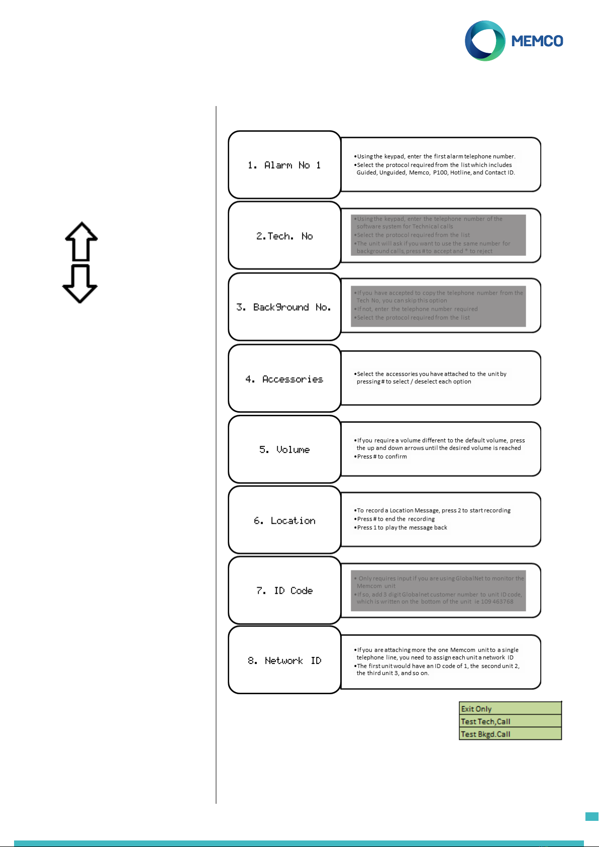
Tel. Numbers >
Alarm no. 1
Alarm no. 2
Alarm no. 3
Alarm no. 4
Tech.no.
Background no.
Call attempts
Settings >
Codice ID
Volume
Accessories >
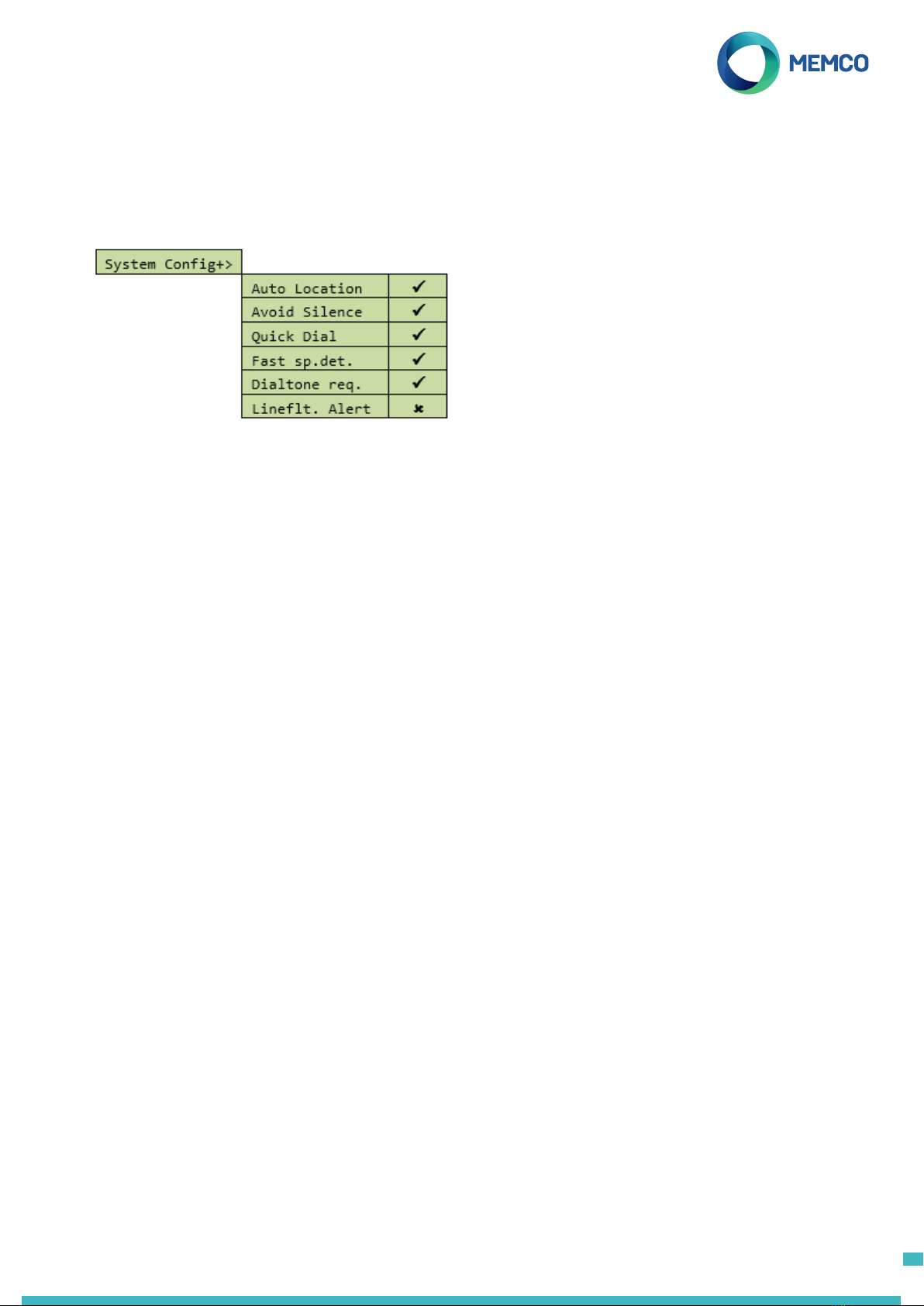
System Cong >
System Cong+ >
HW Monitoring >
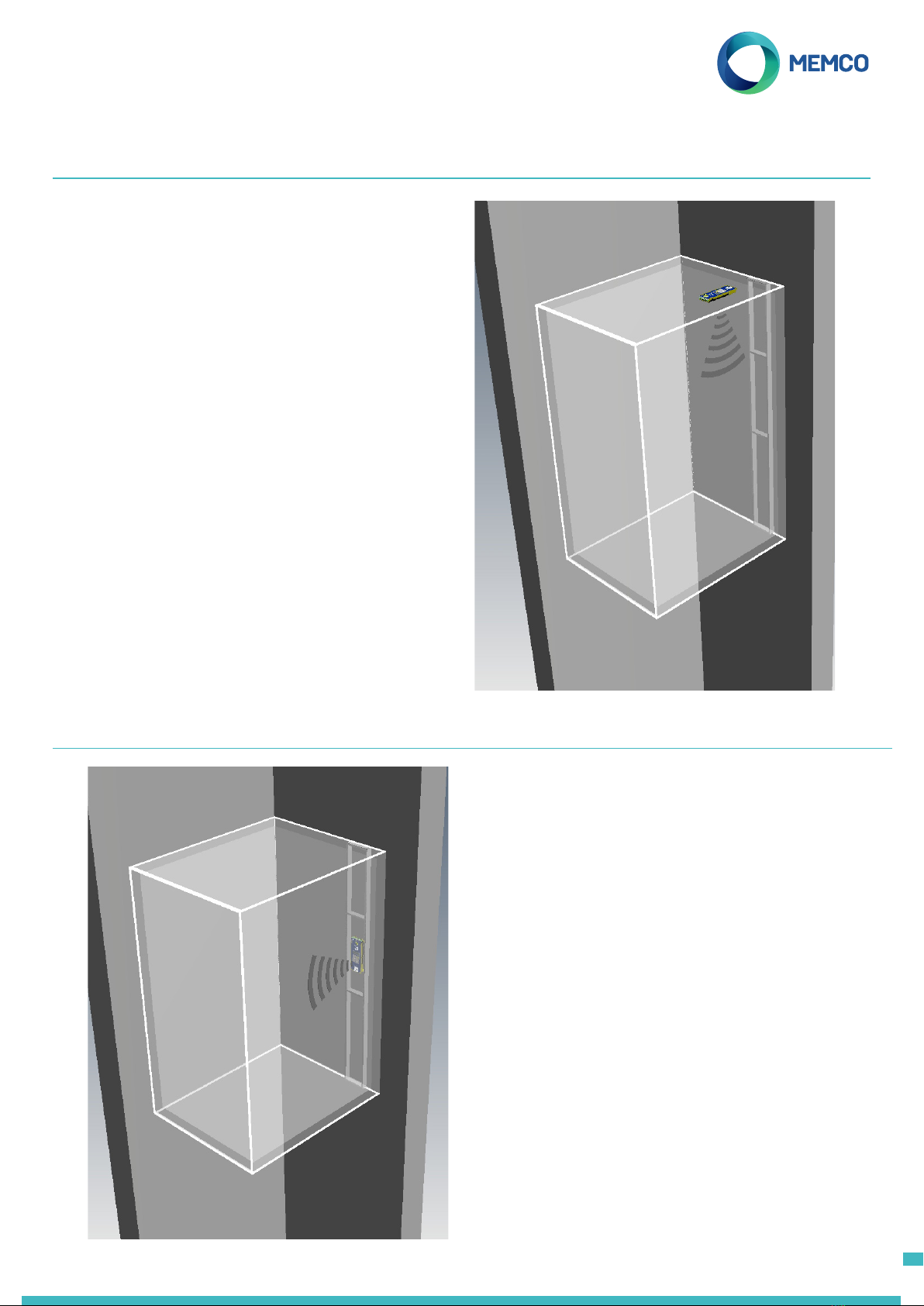
Lift Monitor
IP1 only
iP1+iP2 (Serv.)
Service Count
Interval
Live Count
Delays >
COP delay
MPS delay
TOC delay
Tech IP1 delay
Tech IP2 delay
Hangup delay
Answer delay
Messages >
Location
Reassurance
Guidance
Time / Date >
Time
Date
Advanced >
Passcode
Network ID
Next EN81 call
PBX Frequency
Language >
Relay Mode >
Relay Override >
HW Cong >
GMT Oset
DTMF RX
Menu Sections continued...
Settings
ID Code
Not required in Australian market.
Volume
Press the up and down arrows to adjust the volume and press # to
conrm.
Accessories
System Cong
System Cong >
Multi-dial Sets the unit to call each of the
programmed alarm numbers one after
the other.
EN81-28 Mode Prevents the unit from accepting
incoming calls when not in an alarm
state and requires a passcode to enter
remote programming.
Consec. dial Changes the dialling sequence; all
call attempts to the rst number are
completed before unit attempts to call
the second number and so on.
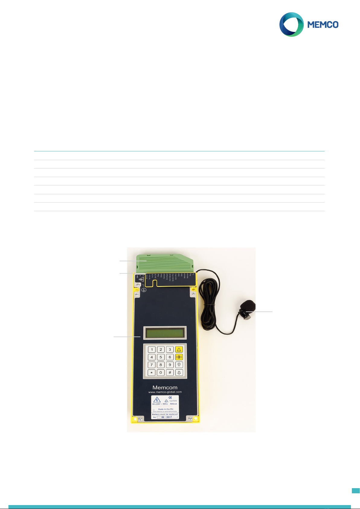
Ext. mic. record Only use if directed by Avire Technical
Support
Alt. dial tone Allows system to work with an
intermittent dial tone.
TOC int. mic. This option activates the internal mic
on the Memcom+unit during alarm
calls form the unit or during MPS calls.
Required if the External Mic does not
clearly pick up speech from the TOC
position.
Verbal c/down Units gives a verbal countdown until
the emergency call is placed.
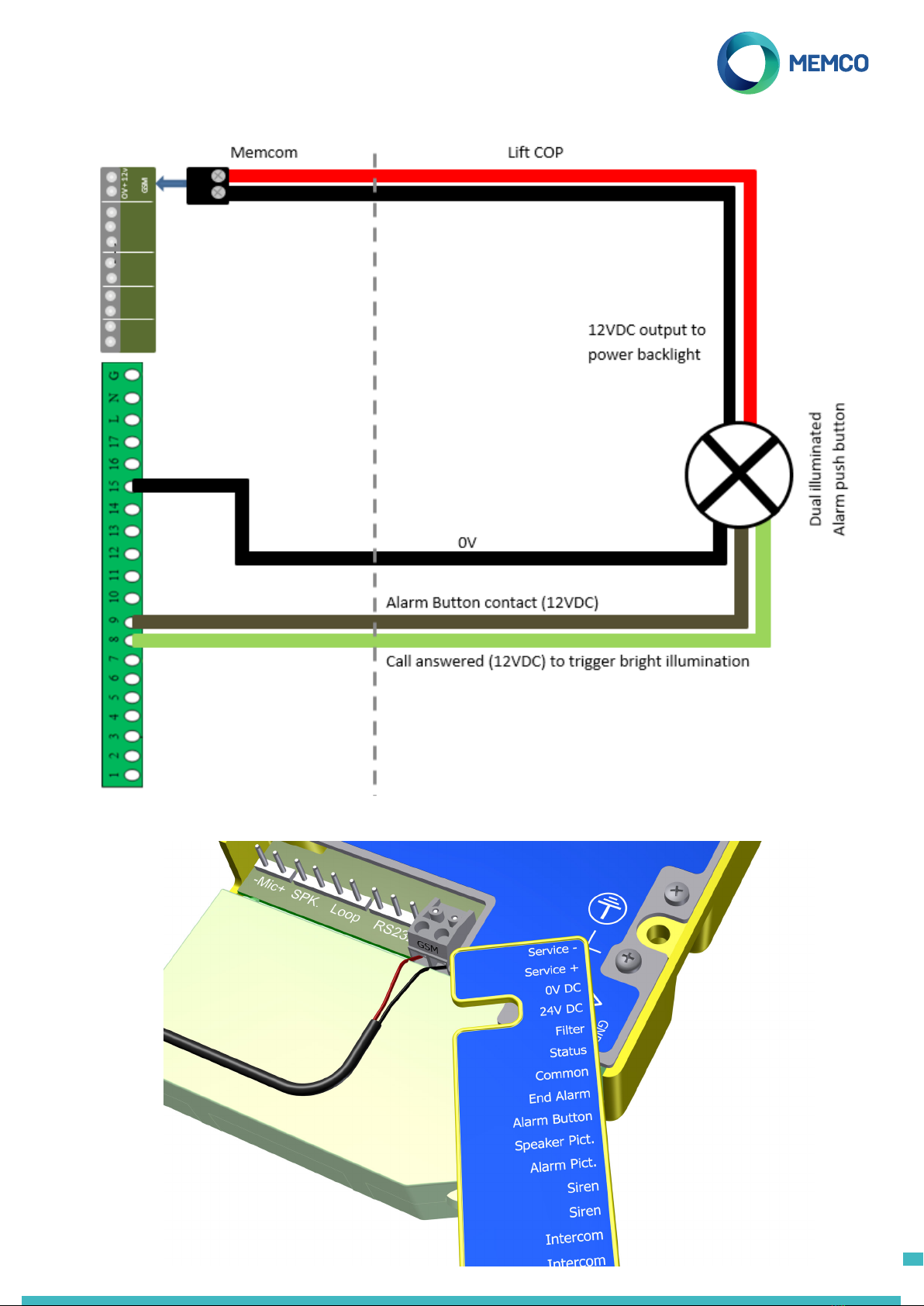
N/C alarm push Select option if connecting to a N/C
alarm push contact
Service as alm Select option if connecting to an alarm
push with voltage to connections
16 & 17
Passcode? Require a passcode to be entered
before accessing the ‘System Cong’
menu.
EOA Pictogram Sets the system to keep the alarm
pictogram lit whilst the unit is in an
alarm state.
Alarm Tone Sets the unit to emit a tone from the
internal speaker when the alarm push
is pressed.
Accessories >
External mic Set to ‘ü‘ as default. De-select this
option if you are not using the external
microphone
COP Accessory Select this option if connecting the
Memcom+to an Avire COP accessory
Memco GSM Select this option if connecting the
Memcom+to a memco GSM with part
number 452 000
9