AVK SERIES 601, 602, 603 & 605 UNIVERSAL COUPLINGS, ADAPTORS & END CAPS
INSTALLATION, OPERATION & MAINTENANCE MANUAL
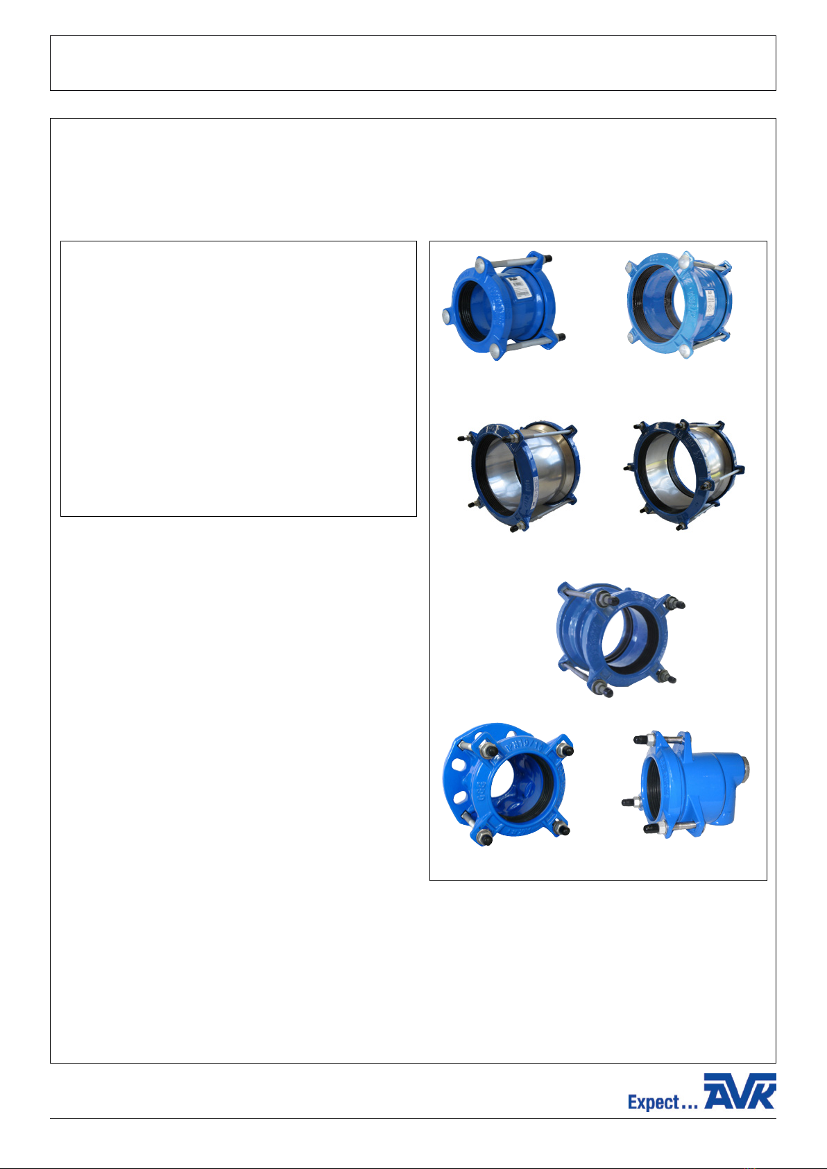
2. Installation
• All of the Series 600 mechanical fittings are supplied as an assembled unit ready for use, dismantling of the parts is
unnecessary.
• Examine the fitting before assembling to ensure that no damage has occurred during transit.
• Check that the sealing range indicated on the label of the fitting is compatible with the actual pipe diameter/s.
• When assembling Universal Flange Adaptors, check that the Nominal flange size and pressure ratings are compatible with
the valve.
• Check that the sealing element supplied is suitable for the medium conveyed in the pipeline.
• Examine pipe ends to which the fitting is to be assembled, ensuring that they are round and square and free from dents,
bulges and score marks.
• When assembling to a steel pipe which has longitudinal seam welds, the weld seam must be removed by grinding. Care
should be taken to ensure that the pipe surface profile is maintained.
• Pipe end(s) must be cleaned by wire brushing, to remove all rust, scale or debris etc...
• Align pipe end(s) maintaining the correct level and concentricity, whilst leaving sufficient gap between pipe ends to allow
installation of the fitting. Ensure deflection does not exceed ±4° per connection.
COUPLINGS
• To provide indication that the coupling has been assembled central over the pipe ends, mark both pipe ends at a distance
equal to half the length of the barrel + half the setting gap.
BARREL LENGTH OF FITTING + SETTING GAP
DISTANCE OF MARK FROM EACH PIPE END = 2
Example: 601-133000-4312, Barrel length = 100mm
Setting gap = 20mm (see below)
100+20
DISTANCE OF MARK FROM EACH PIPE END = 2
= 60mm
• RECOMMENDED GAP SETTINGS
DN40 to DN200 Maximum setting gap = 20mm
DN250 to DN400 Maximum setting gap = 37mm
• Slide coupling onto the fixed pipe end (use necessary lubricant as appropriate).
• Slide free pipe end into coupling, ensuring that the markings on both pipe ends line up with the ends of the fitting.
• Tighten diametrically opposed bolts as indicated on label, to ensure that the sealing element is loaded evenly. It is essential
that all bolts are torqued using a torque wrench evenly as indicated on the label.
6
Nm
5
1 3
24
Torque Setting:
3 bolt couplings 60-70Nm
4 bolt or more 40-50Nm
Bolt Torquing Sequence
Note: S/S fasteners should not be reused.
A
VK
Wang
Pty
Ltd,
Cnr
Sandford
Road
&
Gibson
Street,
W
angaratta,
VIC
3677,
Australia
-
T
:
+61
8
8368
0900
-
E:
[email protected] -
W:
www.avkcivil.com.au
V
ersion
number
4
COPYRIGHT©AVK GROUP A/S 2017 pp. 5 of 6