manuals.online logo
Brands
  1. Home
  2. •
  3. Brands
  4. •
  5. Avlite
  6. •
  7. Floodlight
  8. •
  9. Avlite AV-HL-FL User manual

Avlite AV-HL-FL User manual

Other Avlite Floodlight manuals

Avlite AV-HL-FL Series Supplement

Avlite

Avlite AV-HL-FL Series Supplement

Avlite AV-FL-DC Supplement

Avlite

Avlite AV-FL-DC Supplement

Avlite Heliport AV-HL-FL User manual

Avlite

Avlite Heliport AV-HL-FL User manual

Popular Floodlight manuals by other brands

V-TAC VT-5192S installation instructions

V-TAC

V-TAC VT-5192S installation instructions

Major tech HLF30CW instruction manual

Major tech

Major tech HLF30CW instruction manual

EuroLite LED Cube user manual

EuroLite

EuroLite LED Cube user manual

EuroLite LED IP FL-100 SMD user manual

EuroLite

EuroLite LED IP FL-100 SMD user manual

Cooper Wheelock XB12 specification

Cooper Wheelock

Cooper Wheelock XB12 specification

Allen + Roth 17624-000 user manual

Allen + Roth

Allen + Roth 17624-000 user manual

ADJ 4 STAGE PAK User instructions

ADJ

ADJ 4 STAGE PAK User instructions

Cooper Lighting EGL91SW233 Specification sheet

Cooper Lighting

Cooper Lighting EGL91SW233 Specification sheet

Max 37496 instruction manual

Max

Max 37496 instruction manual

BEGA 85 143 Instructions for use

BEGA

BEGA 85 143 Instructions for use

Cameo CLPST64Q8W user manual

Cameo

Cameo CLPST64Q8W user manual

Beamz 151.226 user manual

Beamz

Beamz 151.226 user manual

EuroLite LED IP FL-8 user manual

EuroLite

EuroLite LED IP FL-8 user manual

Ledj PERFORMER 36 RGB user manual

Ledj

Ledj PERFORMER 36 RGB user manual

Perel ELS3 user manual

Perel

Perel ELS3 user manual

Perel ELS3WD user manual

Perel

Perel ELS3WD user manual

Xtricity 4-80053 instructions

Xtricity

Xtricity 4-80053 instructions

Stahl 6521/4 Series operating instructions

Stahl

Stahl 6521/4 Series operating instructions

manuals.online logo
manuals.online logoBrands
  • About & Mission
  • Contact us
  • Privacy Policy
  • Terms and Conditions

Copyright 2025 Manuals.Online. All Rights Reserved.

Introduction
The purpose of this Quick Start Guide is to present a brief summary of the steps involved in deploying your Avlite provided floodlight. Your product will
consist of a prewired and preassembled AV-HL-FL light fixture (and solar assembly for solar variants) on a frangible mount assembly.
AUSTRALIA
+61 (0)3 5977 6128
USA
+1 (603) 737 1310
info@avlite.com
www.avlite.com
Quick Start Guide
AV-HL-FL
»Theory Of Operations
AV-HL-FL-PV model: The solar module of the light converts sunlight to an electrical current that is used to charge the battery during daylight
hours. The battery provides power to operate the light at night. For optimum solar charge performance, it is recommended that the unit is
orientated with the solar panels facing East-West.
AV-HL-FL-DC and UM models: The wired fixtures are connected to one another as part of a daisy chain configuration where power, control and
monitoring points are wired in parallel utilizing a single cable route per lighting circuit and junction boxes per fixture. The HLS is controlled from
a primary Helipad Controller which provides power and state transitions to each connected lighting circuit.
»AV-HL-FL
Avlite’s floodlight has been specifically designed for helipads to provide uniform surface lighting where the TLOF and FATO lights need to be
supplemented with floodlighting. The fixture is available in solar (PV) and wired versions (DC and Universal Mains UM).
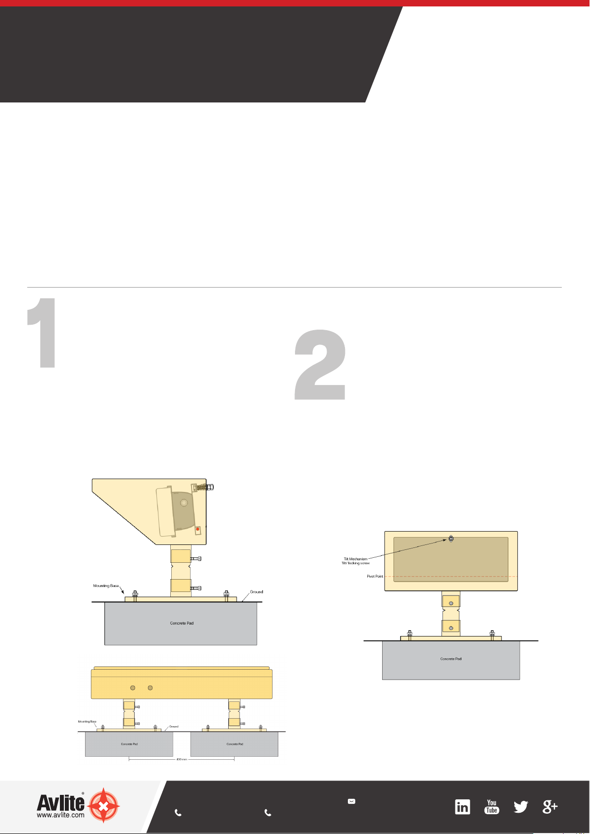
Install the LED Floodlight Units and solar
assembly (if required)
Set up a number of concrete pads at equidistant points
around the TLOF at ground level. The concrete pads
should have a dimension of approximately 400mm
x 400mm with sufficient depth depending on soil
conditions. Embed 4 bolts, using the Mount Base as a
placing template, fitting level when dry. As an alternative,
it is possible to use rubber tiles instead of concrete pads.
Repeat for installing solar assembly, which requires two
concrete pads with 400 mm between the mounting
centrepoints.
AV-HL-FL-PV model only: Connect the LED Floodlight Unit
to the Solar Assembly using the Avlite supplied 2m long
cable.
Adjustment of LED Floodlight Unit
Point the LED Floodlight Unit into the desired direction,
ensuring that the floodlight unit is level and the height is
below 250mm.
Loosen the two nut screws at the back of the LED
Floodlight Unit.
Adjust the Light Head as required by turning the Tilt
Screw Nut. A spring between the LED Floodlight Unit
and the Light Head will provide the required tension.
After the adjustment secure the tilt/position of the Light
Head by tightening the Locking Screw Nut.
If required, tighten the hex sockets at the Frangible
Sleeve
Solar Assembly - Front View
LED Floodlight Unit - Side View
AUSTRALIA
+61 (0)3 5977 6128
USA
+1 (603) 737 1310
info@avlite.com
www.avlite.com
AV-HL-FL_QSG_EN_V1-0
Test and secure
AV-HL-FL-PV models: Test the operation of the light by
using the Radio Controller
Close the PCB enclosure and Solar Assembly. Secure
the lid with the provided bolt.
AV-HL-FL-DC and UM Models: Test the Operation of the
lighting circuits in the Helipad Lighting System using the
Primary Helipad Controller (AV-HL-CTRL-T1 or AV-HL-
CTRL-T2)
Bolt the light to its final location.
Set the Light Group (PV Model Only)
or wire the Floodlight unit (DC and UM
Models Only)
AV-HL-FL-PV models: Determine to which group
each individual light belongs.
Set the light group by adjusting the Rotary Switch
A on the PCB to the appropriate light group (E.g. 0,
1, 2 etc).
AV-HL-FL-DC or UM Models: Wire the LED
Floodlight Unit into the daisy chain configuration via
the junction box. Follow the wiring instructions in
section 7.0 of the Installation Manual.
Need more information?
Please see the AV-HL-FL Installation and Service Manual for full wiring installation at www.avlite.com.
Alwa
y
s On
Dusk till Dawn
Junction Box (UM or DC)
Not e: Power and Data cables
can be wired into the junction
box from the left or right hand
side
Junction Box (UM or DC)
Not e: Power and Data cables
can be wired into the junction
box from the left or right hand
side
Internal wiring to Light
Head Assembly
Junction Box (UM or DC)
Not e: Power and Data cables
can be wired into the junction
box from the left or right hand
side
Internal wiring to Light
Head Assembly
PV Model
DC and UM Models