manuals.online logo
Brands
  1. Home
  2. •
  3. Brands
  4. •
  5. Avlite
  6. •
  7. Floodlight
  8. •
  9. Avlite Heliport AV-HL-FL User manual

Avlite Heliport AV-HL-FL User manual

Other Avlite Floodlight manuals

Avlite AV-HL-FL Series Supplement

Avlite

Avlite AV-HL-FL Series Supplement

Avlite AV-FL-DC Supplement

Avlite

Avlite AV-FL-DC Supplement

Avlite AV-HL-FL User manual

Avlite

Avlite AV-HL-FL User manual

Popular Floodlight manuals by other brands

V-TAC VT-5192S installation instructions

V-TAC

V-TAC VT-5192S installation instructions

Major tech HLF30CW instruction manual

Major tech

Major tech HLF30CW instruction manual

EuroLite LED Cube user manual

EuroLite

EuroLite LED Cube user manual

EuroLite LED IP FL-100 SMD user manual

EuroLite

EuroLite LED IP FL-100 SMD user manual

Cooper Wheelock XB12 specification

Cooper Wheelock

Cooper Wheelock XB12 specification

Allen + Roth 17624-000 user manual

Allen + Roth

Allen + Roth 17624-000 user manual

ADJ 4 STAGE PAK User instructions

ADJ

ADJ 4 STAGE PAK User instructions

Cooper Lighting EGL91SW233 Specification sheet

Cooper Lighting

Cooper Lighting EGL91SW233 Specification sheet

Max 37496 instruction manual

Max

Max 37496 instruction manual

BEGA 85 143 Instructions for use

BEGA

BEGA 85 143 Instructions for use

Cameo CLPST64Q8W user manual

Cameo

Cameo CLPST64Q8W user manual

Beamz 151.226 user manual

Beamz

Beamz 151.226 user manual

EuroLite LED IP FL-8 user manual

EuroLite

EuroLite LED IP FL-8 user manual

Ledj PERFORMER 36 RGB user manual

Ledj

Ledj PERFORMER 36 RGB user manual

Perel ELS3 user manual

Perel

Perel ELS3 user manual

Perel ELS3WD user manual

Perel

Perel ELS3WD user manual

Xtricity 4-80053 instructions

Xtricity

Xtricity 4-80053 instructions

Stahl 6521/4 Series operating instructions

Stahl

Stahl 6521/4 Series operating instructions

manuals.online logo
manuals.online logoBrands
  • About & Mission
  • Contact us
  • Privacy Policy
  • Terms and Conditions

Copyright 2025 Manuals.Online. All Rights Reserved.

For the full manual, visit the link below:
avlite.com/product/product-page-url-NotTheDirectManualLink/
Quick Start Guide
AV-HL-FL
Thank you for purchasing this product. This guide will
provide you with a brief summary of the steps involved in
deploying the AV-HL-FL.
The purpose of this Quick Start Guide is to present a brief summary of the steps involved in deploying
your Avlite provided oodlight. Your product will consist of a prewired and preassembled AV-HL-FL light
xture (and solar assembly for solar variants) on a frangible mount assembly.
Heliport Flood Light AV-HL-FL
Avlite’s oodlight has been specically designed for helipads to
provide uniform surface lighting where the TLOF and FATO lights
need to be supplemented with oodlighting. The xture is available
in solar (PV) and wired versions (DC and Universal Mains UM).
Theory Of Operations
AV-HL-FL-PV model: The solar module of the light converts sunlight to an electrical current that is used to
charge the battery during daylight hours. The battery provides power to operate the light at night. For op-
timum solar charge performance, it is recommended that the unit is orientated with the solar panels facing
East-West.
AV-HL-FL-DC and UM models: The wired xtures are connected to one another as part of a daisy chain con-
guration where power, control and monitoring points are wired in parallel utilizing a single cable route per
lighting circuit and junction boxes per xture. The HLS is controlled from a primary Helipad Controller which
provides power and state transitions to each connected lighting circuit.
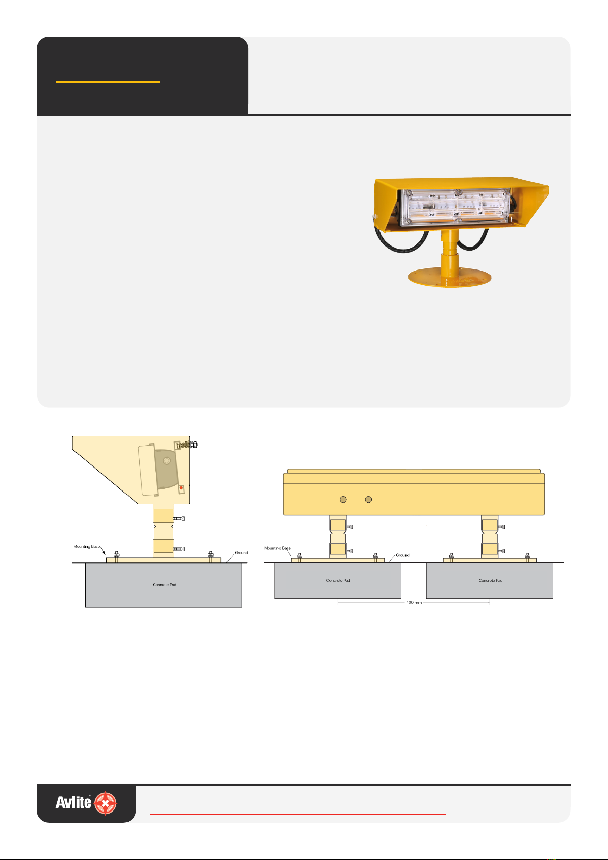
Step 1: Install the LED Floodlight Units
and solar assembly (if required)
Set up a number of concrete pads at equidistant
points around the TLOF at ground level. The
concrete pads should have a dimension of
approximately 400mm x 400mm with sucient
depth depending on soil conditions. Embed 4 bolts,
using the Mount Base as a placing template, tting
level when dry. As an alternative, it is possible to
use rubber tiles instead of concrete pads.
LED Floodlight Unit - Side View Solar Assembly - Front View
Repeat for installing solar assembly, which requires
two concrete pads with 400 mm between the
mounting centrepoints.
AV-HL-FL-PV model only: Connect the LED Flood-
light Unit to the Solar Assembly using the Avlite
supplied 2m long cable.
Head Oce
+61 (0)3 5977 6128
Avlite USA
+1 (603) 737 1311
Avlite Asia
+65 9119 8770
General Enquiries
[email protected]
Step 2: Adjustment of LED Floodlight Unit
AV-HL-FL-PV models: Determine to which group each
individual light belongs.
Set the light group by adjusting the Rotary Switch A on
the PCB to the appropriate light group (E.g. 0, 1, 2 etc).
AV-HL-FL-DC or UM Models: Wire the LED Floodlight
Unit into the daisy chain conguration via the junction
box. Follow the wiring instructions in section 7.0 of the
Installation Manual.
Step 3: Set the Light Group (PV Model Only)
or wire the Floodlight unit (DC and UM Mod-
els Only)
AV-HL-FL-PV models: Determine to which group each
individual light belongs.
Set the light group by adjusting the Rotary Switch A on
the PCB to the appropriate light group (E.g. 0, 1, 2 etc).
AV-HL-FL-DC or UM Models: Wire the LED Floodlight
Unit into the daisy chain conguration via the junction
box. Follow the wiring instructions in section 7.0 of the
Installation Manual.
Step 4: Test and secure
AV-HL-FL-PV models: Test the operation of the light by
using the Radio Controller
Close the PCB enclosure and Solar Assembly. Secure the
lid with the provided bolt.
AV-HL-FL-DC and UM Models: Test the Operation of the
lighting circuits in the Helipad Lighting System using
the Primary Helipad Controller (AV-HL-CTRL-T1 or AV-
HL-CTRL-T2)
Bolt the light to its nal location.
Junction Box (UM or DC)
Not e : Power and Data cables
can be wired int o the junction
box from the left or right hand
side
Junction Box (UM or DC)
Not e : Power and Data cables
can be wired int o the junction
box from the left or right hand
side
Int ern al wi ring to Light
Head Assembly
Junction Box (UM or DC)
Not e : Power and Data cables
can be wired int o the junction
box from the left or right hand
side
Int ern al wi ring to Light
Head Assembly
PV Model DC and UM Models
Alwa
y
s On
Dusk till Dawn