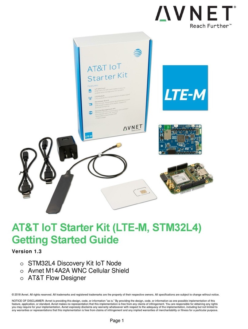
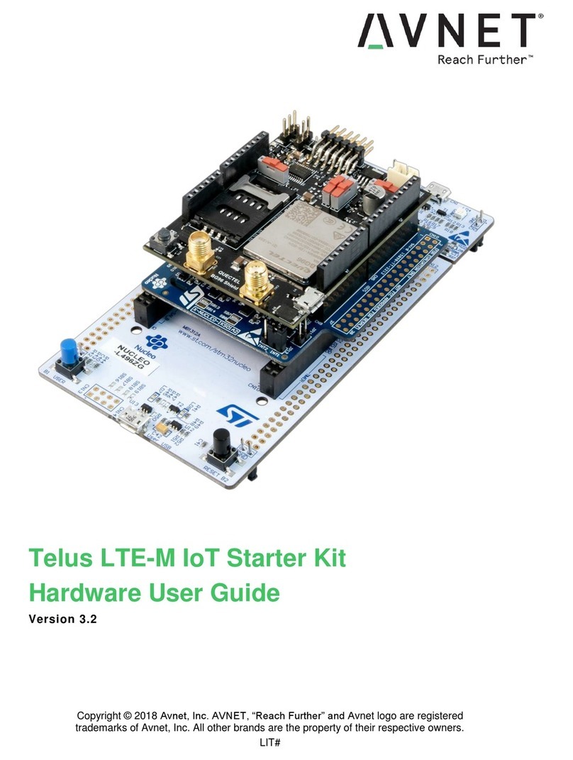
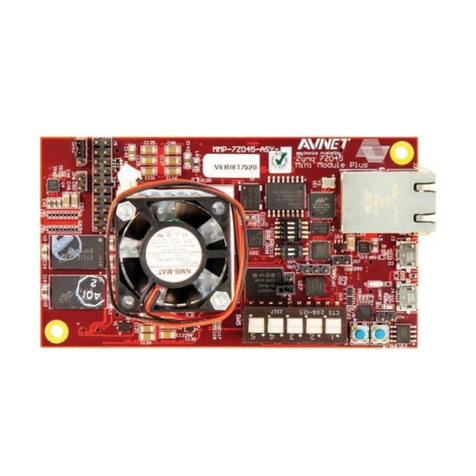
Avnet RFSoC User manual

© 2017 Avnet. All rights reserved. All trademarks and registered trademarks are the property of their respective owners. All specifications are subject to change without notice.
NOTICE OF DISCLAIMER: Avnet is providing this design, code, or information "as is." By providing the design, code, or information as one possible implementation of this feature,
application, or standard, Avnet makes no representation that this implementation is free from any claims of infringement. You are responsible for obtaining any rights you may
require for your implementation. Avnet expressly disclaims any warranty whatsoever with respect to the adequacy of the implementation, including but not limited to any warranties
or representations that this implementation is free from claims of infringement and any implied warranties of merchantability or fitness for a particular purpose.
RFSoC Development Kit
Getting Started Guide
Version 1.6
November 26, 2019

RFSoC Development Kit Getting Started Guide Page 2
Contents
Introduction .................................................................................................................3
Avnet RFSoC Development Kit Overview...................................................................3
Objectives ...................................................................................................................4
Requirements..............................................................................................................4
Tools Setup.................................................................................................................5
Hardware Setup ..........................................................................................................6
Booting ZCU111..........................................................................................................9
Ethernet TCP/IP Connection to ZCU111 ...........................................................................................10
Qorvo Card Control...................................................................................................12
Experiment 1: Generating a CW Tone through the TX Path .....................................14
Frequency Planning...........................................................................................................................15
Configuring the RF-ADC in the DPD observation path......................................................................18
Configuring the RF-DAC in the transmit path ....................................................................................23
Experiment 2: Generating an LTE signal through the TX Path..................................27
Appendix A: Installation of USB UART Driver ..........................................................33
Download and Install the Required Software.....................................................................................33
Determining the Virtual COM Port .....................................................................................................35
Appendix III: Getting Support ....................................................................................37
Avnet Support ....................................................................................................................................37
MathWorks Support ...........................................................................................................................37
Regulatory Compliance Information..........................................................................38
Revision History ........................................................................................................39

RFSoC Development Kit Getting Started Guide Page 3
Introduction
This tutorial serves as an introduction to the Avnet Zynq®UltraScale+TM RFSoC Development Kit with
Qorvo RF Front End. Using the Avnet RFSoC Explorer®graphical user-interface in MATLAB, you will
control the ZCU111 development board, generate and acquire signals through the Qorvo front-end card.
DISCLAIMER: This tutorial is provided for reference/educational purposes only and may not reflect
results observed with other test equipment.
Avnet RFSoC Development Kit Overview
The Avnet Zynq UltraScale+ RFSoC Development Kit with Qorvo RF Front End enables system
architects to explore the entire signal chain from antenna to digital using tools from MathWorks and
industry-leading RF components from Qorvo. We extend the functionality of the Xilinx Zynq UltraScale+
RFSoC ZCU111 Evaluation Kit by adding the Qorvo 2x2 Small Cell RF front-end card, plus native
connection to MATLAB®& Simulink®with Avnet's RFSoC Explorer®application.
Please consult www.avnet.com/rfsockit or contact your local Avnet FAE for further details.
Figure 1 - Avnet Zynq UltraScale+ RFSoC Development Kit with Qorvo RF Front End

RFSoC Development Kit Getting Started Guide Page 4
Objectives
This tutorial is intended to help you:
Gain familiarity with the Avnet RFSoC Development Kit with Qorvo RF Front End
Use the Avnet RFSoC Explorer GUI to control the hardware, generate and acquire signals into
MATLAB through the RF signal chains of the Qorvo card
Explore the Avnet RFSoC Explorer user API for automated scripting and interface to MATLAB
Requirements
Laptop or PC with the following software installed:
MATLAB R2019b (Free MATLAB Trial Package for Wireless Communications available)
i
oDSP System Toolbox
oFixed-Point Designer
oCommunications Toolbox
oCommunications Toolbox Support Package for Xilinx Zynq-Based Radio
oSignal Processing Toolbox
oLTE Toolbox (optional)
o5G Toolbox (optional)
Avnet Zynq UltraScale+ RFSoC Development Kit with Qorvo RF Front End
USB cable (Type A to Micro-USB Type B)
CAT5 Ethernet cable
Xilinx Vivado software is not required.

RFSoC Development Kit Getting Started Guide Page 5
Tools Setup
RFSoC Explorer installs easily in the MATLAB APPS tab without modifying your registryor other applications.
1. From MATLAB Add-Ons, search for Avnet RFSoC Explorer and click install.
2. From MATLAB Add-Ons, search for Communications Toolbox Support Package for
Xilinx Zynq-Based Radio and click install.
After installation, choose Configure later if prompted.

RFSoC Development Kit Getting Started Guide Page 6
Hardware Setup
The Avnet RFSoC Development Kit includes the Xilinx Zynq ZCU111 Evaluation Kit. There are many
jumpers and switches on the board, shipped with default states, which do not need to change for this
tutorial. In the following steps we describe the minimal configuration. For a comprehensive setup guide,
refer to the online ZCU111 Xilinx Wiki (ZCU111 RFSoC RF Data Converter Evaluation Tool Getting
Started Guide).
1. Set the ZCU111 DIP switches (SW6) as shown in the figure below, which allows the ZCU111
board to boot from the SD card.
Figure 2 - ZCU111 SD boot switch settings
2. Remove the SD card from the ZCU111 and insert into your PC. Use an SD formatter tool to
create a FAT partition, https://www.sdcard.org/downloads/formatter_4/
Figure 3 - SD card formatter
3. Download the file avnet_rfsocX_zcu111_boot_v1_0.zip from www.avnet.com/RFSockit.
a. Direct link http://avnet.me/rfsocX-zcu111-boot-v1.0

RFSoC Development Kit Getting Started Guide Page 7
Figure 4 - SD Card Download
This archive contains the software for the ZCU111 evaluation board.
Unzip the archive to a convenient location on your hard disk, then copy the files to the root level
of the SD card. Safely eject the SD card from the PC and replace into ZCU111.
Figure 5 - SD Card Root Directory with Boot Files
4. To enable your PC to make a serial connection to the ZCU111 USB-UART, you must install the
Silicon Labs CP210x USB to UART Bridge VCP Drivers. For step-by-step instructions see
Appendix A: Installation of USB UART Driver later in this document.
5. Connect the Qorvo RF card, ZCU111, antennae, and cables as shown in Figure 6. Although no
over-the-air transmission and reception is involved in this tutorial, the antennae provide
convenient 50-Ohm termination to the PA.
1
6. Plug Ethernet and USB cables into your host PC
1
The Qorvo 2x2 Small Cell RF Front-end 1.8GHz Card is designed for LTE Band-3 small cell applications in
FDD mode. Transmission in the downlink is centered at 1842 MHz; reception in the uplink at 1747 MHz. It is
not intended for over-the-air loopback of TX to RX through the same card, hence the use of DPD observation
path for this tutorial.
For a comprehensive description of the functionality of the RF front-end, see Qorvo 2x2 Small Cell RF Front-
end 1.8 GHz Card Hardware User Guide at www.avnet.com/rfsockit

RFSoC Development Kit Getting Started Guide Page 8
Figure 6 –Qorvo card mounted on ZCU111
Figure 7 - Block diagram of Avnet RFSoC Development Kit

RFSoC Development Kit Getting Started Guide Page 9
Booting ZCU111
1. Turn the ZCU111 power switch ON (near the 12V connector)
From your PC launch a terminal program with 115200/8/n/1/n settings. For the example output shown
here, Tera Term was used. For information on setting up Tera Term to use with the ZCU111 USB-
UART port, see Appendix A: Installation of USB UART Driver later in this document.
2. You should observe terminal output from U-Boot and then Linux output appear in the Tera Term
window. After the final boot message ‘Server Init Done’, press enter to generate a carriage
return and command-line prompt from ZCU111.

RFSoC Development Kit Getting Started Guide Page 10
Ethernet TCP/IP Connection to ZCU111
Upon booting to Linux the ZCU111 Ethernet port should have an IP address. Discover it by running the
ifconfig command.
The ZCU111 Ethernet IP in this example is 192.168.0.105
Set a static IP for your host PC's Local Ethernet adapter. Make sure your PC and the board are on the same
subnet, gateway, etc.
Laptop Ethernet IP: IP 192.168.0.106
Subnet 255.255.255.0
From the host PC, open a Windows command prompt and ping the ZCU111 board to verify Ethernet
connectivity.
C:\> ping 192.168.0.105

RFSoC Development Kit Getting Started Guide Page 11
From the hostPC serial terminal connection to Linux running on the ZCU111, verify Ethernet connectivity
by pinging your host PC.
root@xilinx-zcu111-2018_2:~# ping 192.168.0.106

RFSoC Development Kit Getting Started Guide Page 12
Qorvo Card Control
1. The Qorvo 2x2 Small Cell RF Front-end 1.8GHz Card is controlled from a Linux application
running on the Processing System (PS) APU of the RFSoC. Commands sent from the PC
through the USB_UART of ZCU111 are subsequently transferred to control registers on the
Qorvo card via an SPI BUS. Refer to the Avnet Qorvo 2x2 Small Cell RF Front-end 1.8GHz
Card Hardware User Guide for more information.
iii
At the terminal command-line, type ‘qorvo’to launch the control menu for the Qorvo card.
Note: If you make a mistake while typing commands in the Qorvo control menu, use the
keyboard ‘Delete’ key to backspace at the command line.
Figure 8 - Qorvo card command menu
2. Type ‘v’at the terminal command line, followed by a carriage return, to write default values to all
control registers in the programmable devices of the Qorvo card.

RFSoC Development Kit Getting Started Guide Page 13
3. Type ‘w’at the terminal command line, followed by a carriage return to display all current values.
Note that these are the last values written to the Qorvo registers, not a read back of the device
registers.
4. In preparation for next steps, we shall ensure that no RF output power emerges from the QPA9903
power amplifier (PA) in the TX signal chain of the Qorvo card.
Type ‘e’at the terminal command line followed by a carriage return, then type ‘1’ to disable the TX
TQL9092 driver amplifier.
Type ‘d’at the terminal command line followed by a carriage return, then type ‘0’to disable the
QPA9903 power amplifier.
With the digital attenuators at maximum attenuation, the previous steps have ensured that no signal
power is coupled back from the PA through the DPD observation path on channel 1 of the Qorvo
card to the RF-ADC of RFSoC on ZCU111. This is done for the purpose of calibrating the DPD
observation path RF-ADC in next steps.
Figure 9 –Qorvo card TX signal chain disabled

RFSoC Development Kit Getting Started Guide Page 14
Experiment 1: Generating a CW Tone through the TX Path
The power amplifier (PA) output in each channel of the Qorvo RF card is routed back to an RF-ADC
through a directional coupler, providing an observation path typically used for digital pre-distortion of the
PA. In this experiment we shall generate a CW tone in the digital domain from the RFSoC Explorer
graphical user interface (GUI) running under MATLAB on the host PC. The digital signal data will be
downloaded to the ZCU111 over TCP/IP and stored in DDR4 memory dedicated to the RF-DACs.
Once download is complete, the signal data will be read out of the memory buffer through DMA and
routed to the digital up-converter (DUC) within the RF_DAC tile, interpolated to a higher sampling rate,
frequency-shifted to 1842 MHz through the complex mixer and converted to the analog domain by the
RF-DAC. This process repeats indefinitely, constantly looping back to the start of the data in the memory
buffer after reaching the end to generate a CW tone at the output of the DAC. To avoid discontinuity
between the start and end loop-points of the CW tone, RFSoC Explorer automatically adjusts the signal
length to an integer number of cycles, thereby ensuring a smooth zero-crossing upon looping back to
the start of data.
The directional coupler at the output of the PA routes the RF signal back towards an RF-ADC on the
ZCU111, with 20 dB of attenuation. Normally intended as an observation path for digital pre-distortion
and PA linearization, this provides a convenient means of re-acquiring the PA output signal into the
digital domain without any external connections. Our objective here is simply to demonstrate usage of
RFSoC Explorer to generate and acquire signals and control the RF signal chain; we shall leave PA
linearization for another day.
Figure 10 - TX signal chain and DPD observation path
1. Start MATLAB R2019b
2. In MATLAB, go to the APPS tab and click the icon for Avnet RFSoC Explorer.

RFSoC Development Kit Getting Started Guide Page 15
Figure 11 - Launching RFSoC Explorer
Shown in Figure 12 is the mapping of RFSoC data converters on ZCU111 that connect to signal paths
of the Qorvo RF card. ‘Tile’ and ‘Block’ indices are zero-based. For ADCs, Block (0 => 01; 1 = >23).
Qorvo Signal
CH2_RX
CH2_DPD
CH1_RX
CH1_DPD
CH2_TX
CH1_TX
AMC/Schem.
ADC_01
ADC_03
ADC_05
ADC_07
DAC_00
DAC_06
Tile
0
1
2
3
0
1
Block
1
1
1
1
0
2
Figure 12 - Channel map of ZCU111 data converters
From the main tab of RFSoC Explorer set the Board IP Address that was previously found using the
ifconfig command from the host PC serial terminal connection to Linux running on the ZCU111.
Frequency Planning
Frequency planning involves selecting appropriate sampling rates, Nyquist zone of operation and digital signal
processing according to signal bandwidth, I/F frequency and board-level filtering. In this case the bandwidth
of LTE-band-3 is 75 MHz, centered at 1842 MHz in the downlink.
While the bandwidth of the RF-ADC could easily support direct-RF conversion of the 1842 MHz I/F in the first-
Nyquist zone, the relatively small instantaneous signal bandwidth of 75 MHz would make such an approach
wasteful of resources and power. We shall instead aim to match the response of the digital halfband filters in
the decimation stage of the digital downconverter (DDC) to the bandwidth of the LTE Band-3 signal.

RFSoC Development Kit Getting Started Guide Page 16
The decimation filters are flat out to 80% Nyquist passband or 0.4*Fs.
3
Based on 75 MHz bandwidth of the
LTE Band-3 signal, we derive a suitable sampling rate at the RF- ADC as shown below.
Figure 13 - ADC sampling rate and decimation factor for LTE-band 3
0.4*Fs_ADC/D ≥ 75/2 (MHz)
Solving for Fs_ADC and decimation factor D yields a suitable sampling rate for the RF-ADC.
D = 8
Fs_ADC ≥ 750 MHz
3
Ref: Table 41: Decimation Filter Operating Modes, Xilinx PG269 (v2.1) May 22, 2019

RFSoC Development Kit Getting Started Guide Page 17
Referring to Figure 14, a 1.00 MHz CW tone x(n) generated in the digital domain by RFSoC Explorer is sent
through the interpolation filters and shifted in frequency by the complex mixer in the digital up-converter to
form an analytic signal tone at 1843 MHz. Once converted to the analog domain the signal connects to the
transmit path of the Qorvo card to reach the PA, where it is routed back through a directional coupler to an
RF-ADC within the observation path normally used for PA linearization.
Note that the conversion from the digital to the analog domain produces a real signal with negative frequency
component. The bandpass BAW filter serves as a re-construction filter to attenuate undesired images that
are normally generated at multiples of the DAC sampling rate.
At the RF-ADC the sampling process produces virtual copies in the digital domain of the baseband signal
centered at multiples of the sampling frequency. Careful frequency planning can exploit this phenomenon to
retrieve the signal of interest without need of a high sampling rate that is greater than the highest frequency
component of the analog signal, which in this case is 1843 MHz. By purposely sampling at a lower rate to
create aliasing, copies of the signal can be made to appear at convenient frequency locations outside of the
1st Nyquist zone (0 –Fs/2 Hz). This is known as under-sampling or bandpass sampling. From there, the signal
of interest can be shifted in frequency back to baseband by the complex mixer within the digital down-
converter.
We shall shift to baseband the high-side image appearing at -319.688 MHz due to the alias centered at -
2*Fs_ADC. Mixing with an effective NCO frequency of 320.688 MHz through the complex mixer brings our
original CW tone back to 1 MHz. The signal then passes through three stages of decimation filters to attenuate
any unwanted out-of-band frequency components and noise, reducing the effective sampling rate to 135.168
MSPS, amply satisfying Nyquist for an LTE Band-3 signal bandwidth of 75 MHz.
Figure 14 - Frequency planning for PA observation path for LTE-band 3

RFSoC Development Kit Getting Started Guide Page 18
Configuring the RF-ADC in the DPD observation path
We start by enabling the ADC block for the DPD observation path in channel 1 of the Qorvo RF card,
which connects to ADC07 (Tile 3, Block 1) of the RFSoC device on ZCU111.
1. Enable ADC Tile 3 in RFSoC Explorer. Click to enter the tile.
Figure 15 - RFSoC Explorer Enabling ADC Tile 3
2. Enable ADC23. This is the ADC block that connects to the channel 1 observation path of the Qorvo RF card.
Click OK on the warning box; you will perform ADC calibration in a later step.
Figure 16 –Enabling ADC23 in Tile 3

RFSoC Development Kit Getting Started Guide Page 19
3. Adjust the ADC tile clock to 1081.344 MHz. This controls the sampling rate for both RF-ADCs in the tile.
Figure 17 - Setting RF-ADC sampling rate
4. The NCO frequency for the complex mixer within the digital downconverter represents the shift in frequency
to apply to the signal of interest at the ADC input, centered at Fcin the analog domain. In this case Fc= 1842
MHz for LTE Band-3. We wish to shift the CW tone at 1843 Mhz back to 1 MHz.
The complex mixer operates in the digital domain; NCO frequency settings in the range of -10 GHz to 10 GHz
translate to an 'effective’NCO frequency in the digital domain (from -Fs/2 ... Fs/2). If the analog signal
centered at Fcis in a higher Nyquist zone relative to the ADC sampling rate, a digital alias will be shifted back
to DC. This is sometimes referred to as sub-sampling, as described on page 48 of Zynq UltraScale+ RFSoC RF
Data Converter 2.1 PG269; see endnote v.
Set the ADC complex mixer to -1842 MHz.
Figure 18 - Setting ADC complex mixer frequency

RFSoC Development Kit Getting Started Guide Page 20
Observe the information dialog confirming the 'effective’ NCO frequency. Refer also to Figure 14.
Each of the RF-ADCs in the Zynq UltraScale+ RFSoC is built on multiple sub-ADCs in an interleaving
architecture. The nature of the interleaving process requires that an intricate calibration algorithm be carried
out to obtain the best dynamic range performance from the RF-ADC. It is recommended to remove all signal
power at the input of the RF-ADC during the calibration process; this was accomplished by disabling the TX
signal chain in previous steps. Further details are provided in section ‘RF-ADC Nyquist Zone Operation’ Zynq
UltraScale+ RFSoC RF Data Converter 2.1 PG269
iv
.
RFSoC Explorer automatically calculates and displays Nyquist Zone and Calibration Mode as a function of the
input signal center frequency Analog Fc, and the ADC tile sampling rate.
Finally set decimation to 8X. This will enable the cascade of 3 half-band decimation filters within the RF-ADC
tile to attenuate unwanted frequency components above 67 MHz (at baseband) and reduce the sampling
rate to 135.168 MSPS.
5
Activate the ‘Configure’ pushbutton to perform ADC calibration and download settings to the RF-ADC tile.
5
This sampling rate is sufficient for the purpose of demonstrating acquisition on a CW tone. In a true PA
linearization application it would be necessary to conserve greater excess bandwidth through the observation
path to capture any non-linear distortion products from the PA beyond the signal bandwidth. The useable
bandwidth through the BAW filter in the DPD observation path is approximately 180 MHz, from 1750 to 1930
MHz.
This manual suits for next models
1
Table of contents
Other Avnet Microcontroller manuals