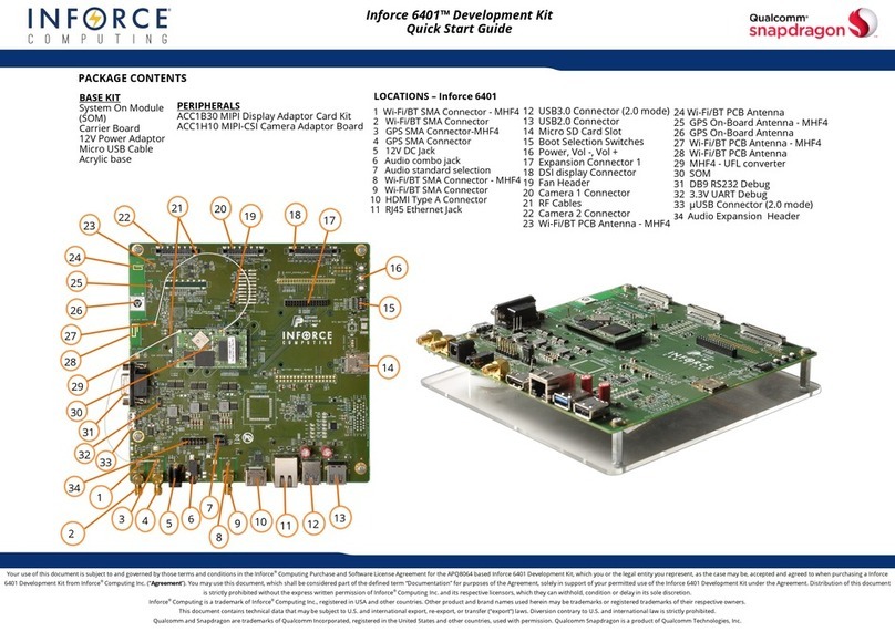
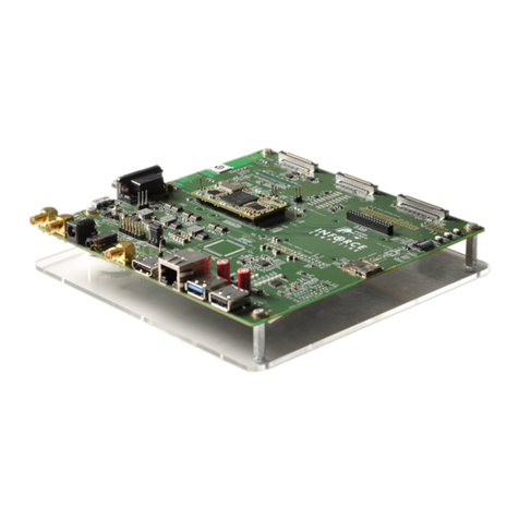
inforce SYS644 P1 Series User manual

Confidential and Proprietary –Inforce Computing Inc.
NO PUBLIC DISCLOSURE PERMITTED: Please report postings of this document on public servers or web sites to:
techsupport@inforcecomputing.com.
Restricted Distribution: Not to be distributed to anyone who is not an employee of either Inforce Computing or its
subsidiaries without the express approval of Inforce Computing.
Not to be used, copied, reproduced, or modified in whole or in part, nor its contents revealed in any manner to others
without the express written permission of Inforce Computing, Inc.
Inforce Computing is a trademark of Inforce Computing Incorporated, registered in the United States and
other countries. All Inforce Computing Incorporated trademarks are used with permission. Other product
and brand names may be trademarks or registered trademarks of their respective owners.
This technical data may be subject to U.S. and international export, re-export, or transfer (“export”) laws. Diversion
contrary to U.S. and international law is strictly prohibited.
Inforce Computing Inc.
48820 Kato Road, # 600B
Fremont, CA 94538
U.S.A.
© 2013 Inforce Computing Inc.
SYS644X-XX-P1
User Guide
001703 Rev. A
May 26, 2013
Submit technical questions at:
https://www.inforcecomputing.com/techweb/

SYS644X-XX-P1 User Guide
001703 Rev. A MAY CONTAIN U.S. AND INTERNATIONAL EXPORT CONTROLLED INFORMATION i
Confidential and Proprietary –Inforce Computing, Inc.
Provided under NDA
Revision history
Revision
Date
Description
Author
A
February 2013
Initial release
Sebastian V P
Approval Record
Function
Position
Name
Date
Checked By
Project Engineer
Sebastian
Reviewed By
Project Engineer
Arun V S
Approved By
Project Manager
Devaraj P S

SYS644X-XX-P1 User Guide License Agreement
001703 Rev. A MAY CONTAIN U.S. AND INTERNATIONAL EXPORT CONTROLLED INFORMATION ii
Confidential and Proprietary –Inforce Computing, Inc.
Provided under NDA
License Agreement
Your use of this document is subject to and governed by those terms and conditions in the Inforce
Computing Purchase and Software License Agreement for the APQ8064 based 644x development
platform, which you or the legal entity you represent, as the case may be, accepted and agreed to when
purchasing a 644x development platform from Inforce Computing Inc. (“Agreement”). You may use this
document, which shall be considered part of the defined term “Documentation” for purposes of the
Agreement, solely in support of your permitted use of the 644x development platform under the
Agreement. Distribution of this document is strictly prohibited without the express written permission of
Inforce Computing Inc. and its respective licensors, which they can withhold, condition or delay in its sole
discretion.
InforceComputing is a trademark of InforceComputing Inc., registered in USA and other countries.
Qualcomm is a trademark of Qualcomm Inc, registered in the United States and other countries. Other
product and brand names used herein may be trademarks or registered trademarks of their respective
owners.
This document contains technical data that may be subject to U.S. and international export, re-export, or
transfer (“export”) laws. Diversion contrary to U.S. and international law is strictly prohibited.

SYS644X-XX-P1 User Guide Safety Warning
001703 Rev. A MAY CONTAIN U.S. AND INTERNATIONAL EXPORT CONTROLLED INFORMATION iii
Confidential and Proprietary –Inforce Computing, Inc.
Provided under NDA
Safety Warning
IMPORTANT SAFETY & REGULATORY INFORMATION
DO NOT DISCARD –DOCUMENT MUST REMAIN WITH DEVICE
ENGINEERING DEVELOPMENT DEVICE - NOT FOR SALE OR LEASE
This device is intended for Laboratory Use Only!
Do Not Operate in Residential or Open Office Environment!
This device has not been tested or approved by any agency or approvals body for Electrical Safety,
Electromagnetic Compatibility, or Telecommunications at the time of distribution.
Safety Testing and Certification that may be required for installation and operation in your region has not
been completed.
SAFETY WARNINGS and CAUTIONS - Please pay attention to the following warnings and cautions
Hazardous Voltage may be present: Special measures and precautions must be taken when using this
device. Some potentials (voltages) on the device may present a hazard to the user. This device should
only be used by technicians and engineers with knowledge and training in working with these types of
devices that contain live circuits.
Power Supply Hazardous Voltage: AC mains voltages are present within the power supply assembly.
This device is supplied with an agency approved power supply. If an alternate power supply is used with
this device, the power supply must be connected to a Listed Type, standalone power supply that is
agency approved for the country of operation. Example, UL Listed supply for the USA. This is a
completely enclosed power supply, of the proper rated voltage and current. No user serviceable parts
inside the power supply.
WARNING
RISK OF ELECTRIC SHOCK
Connect only to a properly earth grounded outlet.
Apparaten skall anslutas till jordat uttag när den ansluts till ett nätverk.
Power Connect and Disconnect: The AC power supply cord is the main disconnect device to mains (AC
power). The socket outlet shall be installed near the equipment and shall be readily accessible

SYS644X-XX-P1 User Guide Safety Warning
001703 Rev. A MAY CONTAIN U.S. AND INTERNATIONAL EXPORT CONTROLLED INFORMATION iv
Confidential and Proprietary –Inforce Computing, Inc.
Provided under NDA
IMPORTANT SAFETY & REGULATORY INFORMATION
DO NOT DISCARD –DOCUMENT MUST REMAIN WITH DEVICE
ENGINEERING DEVELOPMENT DEVICE - NOT FOR SALE OR LEASE
This device is intended for Laboratory Use Only!
Do Not Operate in Residential or Open Office Environment!
SAFETY WARNINGS and CAUTIONS - Please pay attention to the following warnings and cautions
Installation and Maintenance: Do not connect/disconnect any cables to or perform
installation/maintenance on this device during an electrical storm.
WARNING
RISK OF ELECTRIC SHOCK
Do not attempt to modify or use the supplied AC power cord if it
is not the exact type and rating required.
Power Cord Requirements: The connector that plugs into the wall outlet must be a grounding-type male
plug designed for use in your region. It must have certification marks showing certification by an agency
in your region. The connector that plugs into the AC receptacle on the power supply must be an IEC 320,
sheet C13, female connector. See the following website for more information
http://kropla.com/electric2.htm.
General Use and Set Up: Care must be taken at all times to avoid dropping, spilling, or allowing objects
to be placed on the device. Due to the fact that electrical circuits are exposed on these devices, keep all
metal objects such as rings, watches, screw drivers, etc away from the devices and power supply.
Cooling Requirements: Leave a minimum clearance area of 2 inches (5 centimeters) around the side,
front, and back of the development device for cooling purposes.
Thermal and Mechanical Injury: Some components such as heat sinks, power regulators, and
processors may be hot; care should be taken to avoid contact with these components.

SYS644X-XX-P1 User Guide Safety Warning
001703 Rev. A MAY CONTAIN U.S. AND INTERNATIONAL EXPORT CONTROLLED INFORMATION v
Confidential and Proprietary –Inforce Computing, Inc.
Provided under NDA
IMPORTANT SAFETY & REGULATORY INFORMATION
DO NOT DISCARD –DOCUMENT MUST REMAIN WITH DEVICE
ENGINEERING DEVELOPMENT DEVICE - NOT FOR SALE OR LEASE
This device is intended for Laboratory Use Only!
Do Not Operate in Residential or Open Office Environment!
SAFETY WARNINGS and CAUTIONS - Please pay attention to the following warnings and cautions
Electrostatic Discharge Warning: This device must be installed on a properly grounded ESD protection
surface to avoid damage to the components. A properly grounded ESD wrist strap must be worn during
operation/installation of the device, or connection of cables.
Electro Magnetic Interference: This equipment has not been tested for compliance with emissions limits
of FCC and similar international regulations. This device is not, and may not be, offered for sale or lease,
or sold, or leased until authorization from the United States FCC or its equivalent in other countries has
been obtained. Use of this equipment in a residential location is prohibited. This equipment generates,
uses and can radiate radio frequency energy which may result in harmful interference to radio
communications. If this equipment does cause harmful interference to radio or television reception, which
can be determined by turning the equipment on and off, the user is required to take measures to eliminate
the interference or discontinue the use of this equipment.
Lead Content:
Please recycle this device in a responsible manner. Refer to local environmental regulations for proper
recycling; do not dispose of device in unsorted municipal waste.

SYS644X-XX-P1 User Guide Preface
001703 Rev. A MAY CONTAIN U.S. AND INTERNATIONAL EXPORT CONTROLLED INFORMATION vi
Confidential and Proprietary –Inforce Computing, Inc.
Provided under NDA
Preface
This User guide explains the hardware, software, mechanical specifications, setup and usage of system
SYS644X.
Intended Audience
This document is intended for technically qualified personnel. It is not intended for general audiences.
Intended Use
All Inforce boards are evaluated as Information Technology Equipment (I.T.E.) for use in personal
computers (PC) for installation in homes, offices, schools, computer rooms, and similar locations. The
suitability of this product for other PC or embedded non-PC applications or other environments, such as
medical, industrial, alarm systems, test equipment, etc. may not be supported without further evaluation
by Inforce Computing.
Document Organization
The chapters in this document are arranged as follows:
1. Scope
2. Overview
3. Hardware specification
4. System setup and usage
5. Software specification
6. Appendix A
7. Company contact information
Conventions
The following conventions are used in this document:
CAUTION
Cautions warn the user about how to prevent damage to hardware or loss of data.
NOTE
Notes call attention to important information.
REFERENCES
1. Qseven-Spec_2.0
2. Mini ITX Specification

SYS644X-XX-P1 User Guide Preface
001703 Rev. A MAY CONTAIN U.S. AND INTERNATIONAL EXPORT CONTROLLED INFORMATION vii
Confidential and Proprietary –Inforce Computing, Inc.
Provided under NDA
Note
This document is subject to change without notice.
Support Information
Every effort has been made to ensure the accuracy of the document. If you have any comments,
questions, or ideas regarding the user guide, Contact technical support:
techsupport@inforcecomputing.com

SYS644X-XX-P1 User Guide Terminology
001703 Rev. A MAY CONTAIN U.S. AND INTERNATIONAL EXPORT CONTROLLED INFORMATION viii
Confidential and Proprietary –Inforce Computing, Inc.
Provided under NDA
Terminology
The table below gives descriptions to some common terms used in the User Guide.
Term
Description
ANC
Active Noise Cancellation
CSI
Camera Serial Interface
DSI
Display Serial Interface
DDR
Double Data Rate
eMMC
Embedded MultiMedia Card
ESD
Electrostatic discharge
GPS
Global Positioning system
HDMI
High Definition Multimedia Interface
JTAG
Joint Test Action Group
LED
Light Emitting Diode
LVDS
Low Voltage Differential Signaling
MAC
Media Access Control
MIPI
Mobile Industry Processor Interface
NFC
Near Field Communication
OS
Operating System
OTG
On The Go
PCIe
Peripheral Component Interconnect Express
SPDIF
Sony/Philips Digital Interconnect Format
SATA
Serial Advanced Technology Attachment
SIM
Subscriber identity module
SDC
Secure Digital Controller
SPI
Serial Peripheral Interface
TSIF
Transport Stream Interface
UART
Universal Asynchronous Receiver Transmitter
UIM
User Identity Module
USB
Universal Serial Bus
ANC
Active Noise Cancellation
CSI
Camera Serial Interface

SYS644X-XX-P1 User Guide Table of Content
001703 Rev. A MAY CONTAIN U.S. AND INTERNATIONAL EXPORT CONTROLLED INFORMATION vi
Confidential and Proprietary –Inforce Computing, Inc.
Provided under NDA
Table of Content
1 HARDWARE SPECIFICATION.................................................................................................................2
1.1 INTRODUCTION ................................................................................................................................2
1.2 ARCHITECTURE................................................................................................................................2
1.2.1 SYSTEM ASSEMBLY .................................................................................................................3
1.3 SYSTEM SPECIFICATION ................................................................................................................4
1.4 ELECTRICAL CHARACTERISTICS ..................................................................................................5
1.5 PUSH BUTTON..................................................................................................................................5
1.6 CONNECTORS WITH CUSTOMIZED PIN OUT ...............................................................................6
1.7 BOARD LAYOUT AND SUBSYSTEMS.............................................................................................7
2 SYSTEM SETUP AND USAGE...............................................................................................................13
2.1 HARDWARE SETUP........................................................................................................................13
2.2 HARDWARE OPERATION...............................................................................................................14
2.2.1 BOOT CONFIGURATION.........................................................................................................14
2.2.2 LED INDICATIONS ...................................................................................................................15
2.3 JUMPER SETTINGS........................................................................................................................15
2.3.1 ANTENNA CABLE LOCATION.................................................................................................16
3 SOFTWARE SPECIFICATION................................................................................................................17
3.1 OPERATING SYSTEM.....................................................................................................................17
4 APPENDIX A...........................................................................................................................................18
4.1 DISPLAY ADAPTER BOARD...........................................................................................................18
4.2 CAMERA MODULE..........................................................................................................................18

SYS644X-XX-P1 User Guide Table of Figure
001703 Rev. A MAY CONTAIN U.S. AND INTERNATIONAL EXPORT CONTROLLED INFORMATION vii
Confidential and Proprietary –Inforce Computing, Inc.
Provided under NDA
Table of Figure
Figure 1: Block Diagram............................................................................................................. 2
Figure 2: System Assembly........................................................................................................ 3
Figure 3: Carrier board Top side ................................................................................................ 8
Figure 4: Carrier board bottom view..........................................................................................10
Figure 5: Carrier board Rear Panel...........................................................................................11
Figure 6: QSeven CPU module Top and Bottom.......................................................................12
Figure 7: Boot selection switch..................................................................................................14
Figure 8: Display Adapter board with LCD (3D CAD images)....................................................18

SYS644X-XX-P1 User Guide Table of Table
001703 Rev. A MAY CONTAIN U.S. AND INTERNATIONAL EXPORT CONTROLLED INFORMATION viii
Confidential and Proprietary –Inforce Computing, Inc.
Provided under NDA
Table of Table
Table 1System hardware specification:...................................................................................... 4
Table 2: Push button.................................................................................................................. 5
Table 3: Non –Standard connector list...................................................................................... 6
Table 4: Carrier board locations................................................................................................. 7
Table 5: Rear panel locations....................................................................................................11
Table 6: CPU Module location...................................................................................................12
Table 7: Boot selection..............................................................................................................14
Table 8: Antenna cable locations ..............................................................................................16

SYS644X-XX-P1 User Guide SCOPE
001703 Rev. A MAY CONTAIN U.S. AND INTERNATIONAL EXPORT CONTROLLED INFORMATION 1
Confidential and Proprietary –Inforce Computing, Inc.
Provided under NDA
SCOPE
This document describes the system setup and usage of Qualcomm Snapdragon S4 Pro APQ8064
based on system SYS644X which includes both carrier and Q7 module.
Development Device Notice
This development device contains RF/digital hardware and software intended for engineering
development, engineering evaluation, or demonstration purposes only and is intended for use in a
controlled environment. This device is not being placed on the market, leased or sold for use in a
residential environment or for use by the general public as an end user device.
This development device is not intended to meet the requirements of a commercially available consumer
device including those requirements specified in the European Union directives applicable for Radio
devices being placed on the market, FCC equipment authorization rules or other regulations pertaining to
consumer devices being placed on the market for use by the general public.
This development device may only be used in a controlled user environment where operators have
obtained the necessary regulatory approvals for experimentation using a radio device and have
appropriate technical training. The device may not be used by members of the general population or other
individuals that have not been instructed on methods for conducting controlled experiments and taking
necessary precautions for preventing harmful interference and minimizing RF exposure risks. Additional
RF exposure information can be found on the FCC website at http://www.fcc.gov/oet/rfsafety/.
Anti-Static Handling Procedures
Development Kit has exposed PCB and chips. Accordingly, proper anti-static precautions should be
employed when handling the kit, including:
Use a grounded anti-static mat
Use a grounded wrist or foot strap
Hardware Identification Labels
Labels are present on the CPU board and the mini-ITX form-factor carrier board. The following
information is conveyed on these two boards:
CPU board:
Serial Number
Mini-ITX form-factor carrier board:
Serial Number
Ethernet MAC address

SYS644X-XX-P1 User Guide HARDWARE SPECIFICATION
001703 Rev. A MAY CONTAIN U.S. AND INTERNATIONAL EXPORT CONTROLLED INFORMATION 2
Confidential and Proprietary –Inforce Computing, Inc.
Provided under NDA
1 HARDWARE SPECIFICATION
1.1 INTRODUCTION
SYS644x Development Kit provides a reference design for Qualcomm Snapdragon S4 Pro APQ8064
where customers can design, develop, test, and deploy their product solutions around the processor.
1.2 ARCHITECTURE
Development Kit is comprised of two subsystems. A Base kit includes a CPU board and a Carrier Board.
The CPU board includes the Qualcomm Snapdragon S4 Pro APQ8064 processor and memory. This core
board should be connected to the included Mini-ITX form-factor carrier board to provide a functional
development platform for your development.
Figure 1: Block Diagram

SYS644X-XX-P1 User Guide HARDWARE SPECIFICATION
001703 Rev. A MAY CONTAIN U.S. AND INTERNATIONAL EXPORT CONTROLLED INFORMATION 3
Confidential and Proprietary –Inforce Computing, Inc.
Provided under NDA
1.2.1 SYSTEM ASSEMBLY
Following image shows the overall system.
Figure 2: System Assembly

SYS644X-XX-P1 User Guide HARDWARE SPECIFICATION
001703 Rev. A MAY CONTAIN U.S. AND INTERNATIONAL EXPORT CONTROLLED INFORMATION 4
Confidential and Proprietary –Inforce Computing, Inc.
Provided under NDA
1.3 SYSTEM SPECIFICATION
Following table shows the hardware specification of SYS644x
Table 1System hardware specification:
Parameter
Description
Comments
CPU
Qualcomm Snapdragon S4 Pro - APQ8064
4-core, 1.7GHz
RAM
DDR3
2GB
Power
BATTERY (size 18650)
5V Barrel Power Connector
24-pin ATX connector.
Ethernet
10/100/1000Mbps
WiFi/BT
Dual band 2x2 WiFi + Bluetooth 4.0
Storage
eMMC
Expandable upto 64GB
MicroSD card socket
SATA
Navigation
GPS/GLONASS
Display
MIPI-DSI display with Touch screen support
HDMI (HD1080p)
Dual LVDS
USB Ports
microUSB with OTG support
USB type A-B
7x USB 2.0 ports
USB type A connectors
Audio
5.1 Audio in/out
6x 3.5mm ports
Stereo Speaker output
15W output
Camera
2x MIPI-CSI connector
Debug
JTAG
20-pin ARM JTAG
UART
Sensor
Qualcomm Gen6 sensor connector
PLCC Sensor socket
PCIe Interfaces
miniPCIe slot
Standard x1 PCIe slot
Mechanical
dimensions
Q7 Board –70x70mm
Carrier Board –170X170mm

SYS644X-XX-P1 User Guide HARDWARE SPECIFICATION
001703 Rev. A MAY CONTAIN U.S. AND INTERNATIONAL EXPORT CONTROLLED INFORMATION 5
Confidential and Proprietary –Inforce Computing, Inc.
Provided under NDA
1.4 ELECTRICAL CHARACTERISTICS
Power supplies
Sys64xx board is operated from following sources
5V DC Jack (5V , 3A)
ATX power supply ( Standard 20/24pin)
Battery
USB OTG port
Coin cell (Optional)
Power Consumption
Total approximate power of Sys644x is 70W. This will be varied depends on the application and IOs
used.
1.5 PUSH BUTTON
Following are the buttons available on the board.
Table 2: Push button
RefDes
Function
S504
Power Button
S505
Reset
S502
ZOOM/VOL + BUTTON
S503
ZOOM/VOL - BUTTON
SW500
CAMERA BUTTON

SYS644X-XX-P1 User Guide HARDWARE SPECIFICATION
001703 Rev. A MAY CONTAIN U.S. AND INTERNATIONAL EXPORT CONTROLLED INFORMATION 6
Confidential and Proprietary –Inforce Computing, Inc.
Provided under NDA
1.6 CONNECTORS WITH CUSTOMIZED PIN OUT
Some interfaces are terminated on the connectors with non-standard pin outs. Those are given bellow.
Table 3: Non –Standard connector list
Connector
Manufacturer
Part number
Dual LVDS
Hirose
DF9-41P-1V(32)
MIPI-DSI Display
FCI
10106813-064112LF
MIPI-CSI Camera
Samtec
LSHM-120-03.0-L-DV-A-S-K-TR
TSIF / SPDIF
Samtec
QSH-030-01-F-D-A
Expansion Conn.
Samtec
QSH-090-01-F-D-A
NFC
Molex
54722-0164
Education Conn.
Samtec
TST-108-01-T-D
Gen6 Sensor
Samtec
TST-112-01-T-D
NFC
Molex
54722-0164
SPI
Sullins Connector Solutions
PBC05DAAN
Quad MIC
Sullins Connector Solutions
PBC05DAAN
ANC Audio
Amphenol
103-C0680-00842
Power Amp Terminal
Weidmuller
1824420000
NOTE
Refer Technical reference manual for the pin out details

SYS644X-XX-P1 User Guide HARDWARE SPECIFICATION
001703 Rev. A MAY CONTAIN U.S. AND INTERNATIONAL EXPORT CONTROLLED INFORMATION 7
Confidential and Proprietary –Inforce Computing, Inc.
Provided under NDA
1.7 BOARD LAYOUT AND SUBSYSTEMS
Table 4: Carrier board locations
1. MAC address
2. USB Header (Port4&5)
3. PCIe connector
4. SATA -Port B
5. SATA -Port A
6. Coin cell
7. PLCC Socket
8. Sensor header
9. Dual LVDS
10. Expansion Connector
11. mini PCIe connector
12. TSIF/SPDIF Connector
13. MIPI Display connector
14. Education Connector
15. Reset button
16. Power button
17. Zoom/Vol-
18. Zoom/Vol+
19. Camera button
20. Front panel header
21. JTAG connector
22. Boot selection switch
23. Camera-Secondary
24. Camera-Primary
25. battery holder
26. Antenna-GPS
27. Antenna-WIFI
28. Antenna-WIFI/BT
29. S4/Reset/Notify LED
30. Micro USB
31. ATX 24 pin Connector
32.ANC Connector
33. Front panel Audio header
34. Quad MIC
35. USB vertical socket
36. USB Header (Port6&7)
37. SIM Socket
38. NFC Connector
39. MAC Label
40. Serial Label
41. Micro SD card socket

SYS644X-XX-P1 User Guide HARDWARE SPECIFICATION
001703 Rev. A MAY CONTAIN U.S. AND INTERNATIONAL EXPORT CONTROLLED INFORMATION 8
Confidential and Proprietary –Inforce Computing, Inc.
Provided under NDA
Figure 3: Carrier board Top side
Table of contents
Other inforce Microcontroller manuals
Popular Microcontroller manuals by other brands
Xilinx
Xilinx Virtex-4 FX12 Getting started

Samsung
Samsung S3C9454B user manual
GigaDevice Semiconductor
GigaDevice Semiconductor GD32H7 Series Application notes
Analog Devices
Analog Devices EV1HMC8362LP6G user guide
LAPIS Semiconductor
LAPIS Semiconductor ML610Q174 user manual

Mikroe
Mikroe SEMITECH N-PLC Click Application note
