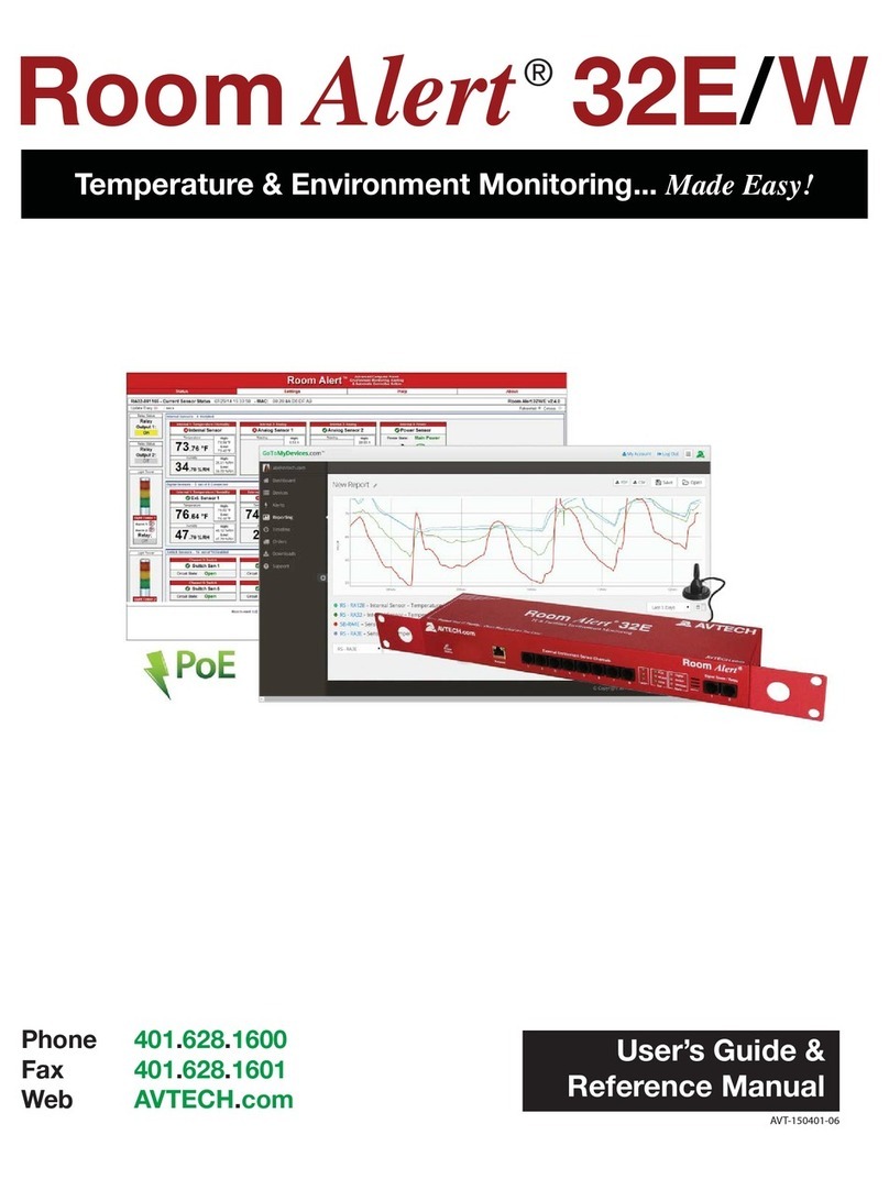
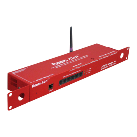
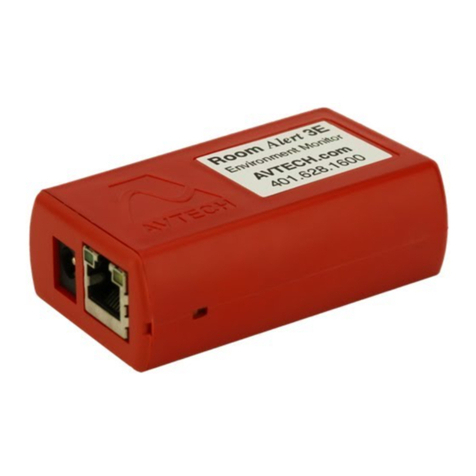
Avtech Room Alert 4E User manual

AVT-150401.06
User’s Guide &
Reference Manual

Install Room Alert Monitors
The Most Advanced, Easy-To-Use, Reliable & Affordable Monitors Available To...
Protect Your Facility...
Don’t Wait Until It’s Too Late!
Digital Temperature
Digital Outdoor Temperature
Digital Fluid Temperature
Digital Humidity
Main / UPS Power
Flood / Water
Current Loops (Amperage)
Extreme Temperature
Heat Index (Feels Like)
Smoke / Fire
Fuel / Water Tank Level
Air Flow, Sound, Light
Motion, Room Entry
Panic Button, Security
Light Towers, Relay Switches
Wireless Sensor Hubs
Network Cameras
Analog Power & Temp Sensors
Switch Sensors
Dry Contacts
Low Voltage Sensors

On behalf of the entire team at AVTECH,
we say, “Thank You!” It is our privilege to
serve you, our valued customer.

Copyright Information
© Copyright 1988-2015 AVTECH Software Inc.
All Rights Reserved. No part of this book may be used or reproduced for commercial benefit in any form or by any means,
or stored in a database or retrieval system, without prior written permission of AVTECH Software Inc., except in the case of
brief quotations embodied in articles and reviews. Making copies of any part of this book for any purpose other than your
individual use is a violation of United States copyright laws and international treaty provisions. For information or additional
copies, contact AVTECH Software Inc., as directed below. Printed in the United States of America.
Warning and Disclaimer
This publication is shipped as is, without warranty of any kind, either express or implied. While every precaution has been
taken in the preparation of this publication, the publisher and authors assume no responsibility for errors or omissions.
Neither is any liability assumed for damages resulting from the use of the information or instructions contained herein. It is
further stated that the publisher and authors are not responsible for any damage or loss to your data or equipment that may
result directly or indirectly from your use of this publication and the related hardware & software. Nothing on any AVTECH
web site or in documentation shall be construed as conferring any license under any of the AVTECH Software (AVTECH) or
any third party’s intellectual property rights, whether by estoppel, implication, or otherwise.
Trademark Acknowledgements
AlertScript, AVTECH, the AVTECH Logo, AVTECH Software, the AVTECH System Manager Character, AVTECH.
com, AVTECHSoftware.com, Environment Alarm, “Environment Monitoring Made Easy!”, EnvironmentMonitor.com,
“GoToMyDevices.com”, “IT Environment Monitoring Made Easy!”, MUPS, Device Discovery, Device ManageR, “Protect
Your Facility... Don’t Wait Until It’s Too Late!”, “Protect Your IT Environment... Don’t Wait Until It’s Too Late!”, Room
Alert, Room Alert Signal Tower, Signal Tower, RoomAlert.com, TemPageR, TemPageR.com and “Temperature Monitoring
Made Easy!”, WiSH, and WiSPR, are trademarks or registered trademarks of AVTECH Software Inc. Any other trademarks,
product or company names mentioned herein are the property of their respective owners and used strictly for the purpose of
identifying compatibility. AVTECH Software Inc. cannot attest to the accuracy of any other organization’s ownership claim to
a trademark and use of any trademark in this publication should not be regarded as affecting the validity of any trademark or
service mark.
Special Thanks
We would like to recognize field test participants, our inhouse support staff and the entire software & hardware development
teams for their contributions and assistance in completing this manual.
Sales, Support & Contact Information
To receive further information or assistance regarding this publication, or any AVTECH product or service, please contact:
Headquarters AVTECH Software Inc.
16 Cutler Street, Cutler Mill
Warren, RI 02885-2761 USA
Email SXSSRUW#VHOOFRP.com
Phone Web 6(//&20.comDYWHFKKWPO
GoToMyDevices.com
RoomAlert.com
Sales 6(//&20
Fax
AVT-150401.06
Room Alert 4E
AVTECH Software, Inc. 1
Table of Contents
Introduction To Room Alert 4E.......................................................................................................3
Room Alert 4E Package Contents....................................................................................................4
The Room Alert 4E ID Box.......................................................................................................4
Front.....................................................................................................................................4
Back .....................................................................................................................................5
How To Install Your Room Alert 4E...............................................................................................7
Step 1: Connect Your Room Alert 4E Hardware......................................................................7
Step 2: Open And View Your Room Alert 4E In Your Web Browser.....................................7
With The Built-In Web Interface.........................................................................................7
With Device ManageR For Advanced Functionality...........................................................8
Step 3: Install Additional Components.....................................................................................8
Connect Included External Sensor(s)...................................................................................8
Connect Compatible Components .......................................................................................9
How To Use Room Alert 4E’s Web Interface...............................................................................10
Status........................................................................................................................................10
Current Sensor Status Bar..................................................................................................11
Sensor Display Area ..........................................................................................................12
Settings.....................................................................................................................................14
Network..............................................................................................................................15
SMTP Email.......................................................................................................................18
Simple Network Management Protocol (SNMP)..............................................................20
Sensors...............................................................................................................................23
Ping Options.......................................................................................................................29
Alarm Options....................................................................................................................30
Security..............................................................................................................................32
Advanced ...........................................................................................................................34

Room Alert 4E
2AVTECH Software, Inc.
Help..........................................................................................................................................39
About........................................................................................................................................40
Updating & Troubleshooting Your Room Alert 4E ......................................................................41
How To Download Firmware & Software Updates From AVTECH.com..............................41
How To Update Room Alert 4E’s Firmware...........................................................................41
How To Discover Room Alert 4E When Your Network Blocks UDP Broadcasts.................42
How To Reset Room Alert 4E To Factory Defaults................................................................42
Introduction To AVTECH’s Device ManageR .............................................................................44
Appendix: Sensor & Product Options
Protect Your Facility… Don’t Wait Until It’s Too Late!
6(//&20.comDYWHFKKWPO

Room Alert 4E
AVTECH Software, Inc. 3
Introduction To Room Alert 4E
The Room Alert 4E monitor is AVTECH’s compact hardware solution for Temperature &
Facilities Environment Monitoring... Made Easy.
The Room Alert 4E has one (1) internal temperature sensor and four (4) external ports: two (2)
external digital, one (1) external switch and one (1) custom Light Tower & Relay Switch Sensor
port.
Install your unit with minimal planning and less hassle.
Get up and running in minutes with easy “Plug and Play” setup.
Mount Room Alert 4E on a rack, on a wall, ceiling or table top.
Get access from anywhere over the web.
Configure, monitor and operate Room Alert 4E with its easy-to-use built-in web interface.
Significantly expand its functionality with AVTECH’s Device ManageR, the powerful
software bundled FREE with all Room Alert monitors.
Have the flexibility to monitor with any SNMP-enabled 3rd-party monitoring application.
Know immediately when physical conditions change.
Set alert thresholds for the built-in and bundled Digital Temperature sensor from -40° to
185° F (-40° to 85° C).
Alert multiple contacts on your team when thresholds are exceeded.
Receive alert notifications by email, email-to-SMS and more on your computer or mobile
phone.
Expand your options as your needs evolve.
Extend your reach by adding an external digital sensor up to 100 feet away and an external
switch sensor up to 900!
Generate clear visible and audible signals by adding a Light Tower.
Automatically turn on/off electrical devices, such as air conditioners or generators, by adding
a Relay Switch Sensor.
Explore your options further with your AVTECH Product Specialist.

Room Alert 4E
Room Alert 4E Package Contents
The standard Room Alert 4E package includes:
•One (1) Room Alert 4E ID Box
•One (1) External Digital Temperature Sensor
•One (1) 10' Ethernet Cable
•One (1) Room Alert 4E User’s Guide & Reference Manual (You’re reading it now.)
•One (1) Package Of Literature & Additional Information
The Room Alert 4E ID Box
Front
Power Port
Back
Reset
Button
Custom
Light Tower/
Relay
Port
Power
Port
Ethernet
Port
Digital
Ports
(2)
Switch
Sensor
Port
(1)
Front
A standard power port connects Room Alert 4E to
an electrical outlet with AVTECH’s International
Power Adapter.
4AVTECH Software, Inc.

Room Alert 4E
Ethernet Port
An RJ-45 port connects Room Alert 4E to your network
via an RJ
-45 network cable.
Digital Sensor Port
s
Two (2) standard RJ-11 jacks connect any AVTECH
digital sensor to your Room Alert 4E via a standard RJ
-
11 (straight through) telephone cord.
Switch Sensor Channel
A pair of dry contacts connects Room Alert 4E to any
AVTECH switch sensor via standard speak
er wire or
low
-voltage 2-wire cable.
Back
Reset Button
A small push button resets Room Alert 4E to factory
default settings
.
Look for the AVTECH logo. Using another power adapter could
damage the Room Alert 4E’s circuit board. If you need one, purchase
it online at VHOOFRP.com. AVTECH has an international power
adapter with a compatible plug style for each and every country.
NOTE
AVTECH Software, Inc. 5

Room Alert 4E
Sample Room Alert 32W Layout
Custom Light Tower & Relay Switch Sensor Port
The custom port allows you to directly connect a Light
Tower or Relay Swit
ch Sensor to the Room Alert 4E.
For more information about AVTECH sensors and accessories,
please refer to the Appendix at the back of this manual
NOTE
6AVTECH Software, Inc.

Room Alert 4E
A
B
How To Install Your Room Alert 4E
Step 1: Connect Your Room Alert 4E Hardware
A. Connect to your network first.
•Connect one end of a standard Ethernet cable
to the Room Alert 4E’s Ethernet port.
•Connect the other end to a network jack.
B. Then connect to a power source.
•Plug one end of AVTECH’s International Power Adapter into the Room Alert 4E’s
power port.
•Plug the other end into a surge-protected power source.
Your Room Alert 4E is now powered and discoverable on your network!
Step 2: Open And View Your Room Alert 4E In Your Web Browser
With The Built-In Web Interface
•Enter your Room Alert 4E’s IP address in your web browser’s address bar to access
the interface.
Use only AVTECH’s International Power Adapter. Others could
damage the Room Alert 4E and void your warranty. If you don’t
have one, please visit our online store at AVTECH.com.
NOTE
AVTECH Software, Inc. 7

Room Alert 4E
OR
With Device ManageR For Advanced Functionality
•Download and install AVTECH’s Device ManageR via your customer account at
AVTECH.com/Downloads.
•Launch it in your web browser at http://localhost:8080.
Step 3: Install Additional Components
Connect Included External Sensor(s)
AVTECH’s external Digital Temperature Sensor, shown here, comes standard with the Room
Alert 4E package.
Please install according to the Installation Note included with it.
Digital Temperature Sensor
8AVTECH Software, Inc.

Room Alert 4E
Sample Of Sensors Available For Room Alert
Connect Compatible Components
If you purchased additional components that are compatible, install them according to the
Installation Notes included with them.
Please refer to Status, Settings, and Alarm Options in this
manual for instructions on viewing and configuring your external
NOTE
Current Loop
Air Flow
Sensor
Temperature & Analog
Sensor
Power
Sensor
Digital
Temperature & Humidity
Sensor
Digital
Temperature
Sensor
AVTECH Software, Inc. 9

Room Alert 4E
How To Use Room Alert 4E’s Web Interface
You may configure your Room Alert 4E through its built-in web interface. To access the
interface, you may either:
•Select your Room Alert 4E in Device ManageR and click the “Open Web” button.
or
•Type the IP address of your Room Alert 4E monitor directly into the address bar of
your web browser.
Your Room Alert 4E’s web interface has 4 tabs:
•Status
•Settings
•Help
•About
Status
To view your Room Alert 4E’s current sensor status, click Status in the navigation bar at the
top of your screen.
10 AVTECH Software, Inc.

Room Alert 4E
Current Sensor Status Bar
Below the Status tab is the Current Sensor Status Bar, where you may view basic information
about your Room Alert 4E and make temporary adjustments to the sensor display.
•You may find your Room Alert 4E’s name, current date & time, and MAC address here.
•To determine if your Room Alert 4E’s firmware is current, you may click Room
Alert 4E vX.X.X at the right.
•To temporarily modify the refresh interval of the Status screen while viewing, which
is 60 seconds (i.e., every 1 minute) by default, you may enter a value in seconds in
the “Update Every” field. Click outside the field to temporarily commit the change.
•To temporarily toggle the temperature scale between Fahrenheit (F) and Celsius (C),
click Fahrenheit or Celsius.
TIP
Your Room Alert 4E must be connected to the internet to check
firmware versions.
Refer to the Advanced section in this manual for instructions on
setting the default status page refresh rate and temperature
scale for Room Alert 4E.
NOTE
AVTECH Software, Inc. 11

Room Alert 4E
Sensor Display Area
In the main viewing pane of the Status tab is the “Sensor Display Area.” Here you may view the
current readings for your sensors, which are displayed in a grid on the screen as follows:
Light Tower
or
Relay Switch
Sensor
(when enabled in
Settings)
Channel 1
Internal
Temperature
Sensor
Channel 2
External
Digital
Sensor
Channel 3
External
Digital
Sensor
Channel 4
External
Switch
Sensor
Pings
(when configured in Settings)
Below the channels, you see the status icons and the labels for your sensors, which you may
configure in Settings Sensors.
Status Icons
Green circle with “
” mark….......
Sensor is in a clear state.
Grey circle……………………......
Sensor has no alarm
threshold set.
Red circle with
“X” mark…...........
Sensor is in an alarm state.
12 AVTECH Software, Inc.

Room Alert 4E
Display All Sensors / Connected Sensors
If you have no external digital sensor connected, you may temporarily hide Channels 2 and 3:
1. To hide the disconnected digital sensor, click Connected Sensors in the Current
Sensors Status Bar as shown here.
2. To toggle the view back to all 4 sensor channels, click All Sensors.
AVTECH Software, Inc. 13

Room Alert 4E
Settings
To access your Room Alert 4E’s settings, click Settings in the navigation bar at the top of your
screen.
TIP
You’ll see a prompt for your username and password whenever
you click Settings. If you have not set up log in credentials for
your Room Alert 4E, simply click OK without entering anything.
14 AVTECH Software, Inc.

Room Alert 4E
Network
Navigate to Settings Network to open the Network Settings screen.
Device Name
To rename your Room Alert 4E:
1. Select the automatically-assigned name in “Device Name” and enter a new one of up to
15 alphanumeric characters.
2. Click Accept Changes at the bottom of your screen to temporarily save your settings.
You may now navigate to another screen; however, if you close the web interface before
the next step, you will lose your changes.
3. Click Save Settings in the navigation bar to the left of your screen. Your Room Alert
will automatically reboot and commit your changes.
IP Address Configuration—DHCP
To obtain an IP address automatically using DHCP:
1. Select Obtain IP Address Automatically.
2. Typically, leave “Auto Configuration Methods” at the default, with “BOOTP,” “DHCP”
and “AutoIP” enabled.
3. Click Accept Changes at the bottom of your screen to temporarily save your settings.
You may now navigate to another screen; however, if you close the web interface before
the next step, you will lose your changes.
AVTECH Software, Inc. 15

Room Alert 4E
4. Click Save Settings in the navigation bar to the left of your screen. Your Room Alert
will automatically reboot and commit your changes.
IP Address Configuration—Static IP
To assign a static IP address:
1. Select Use The Following IP Configuration.
2. In “IP Address,” enter the new static IP address.
3. In “Subnet Mask,” enter the subnet mask.
4. In “Default Gateway,” enter the gateway IP address.
5. In “DNS Server IP,” enter the DNS server IP address.
6. Click Accept Changes at the bottom of your screen to temporarily save your settings.
You may now navigate to another screen; however, if you close the web interface before
the next step, you will lose your changes.
7. Click Save Settings in the navigation bar to the left of your screen. Your Room Alert
will automatically reboot and commit your changes.
Ethernet Configuration
Typically, you may leave the “Ethernet Configuration” section at the defaults, which are shown
below, for immediate use of Room Alert 4E.
TIP
IMPORTANT: Make sure that you do not use an IP address that
is already assigned to another device. Also, set the IP address
within your current subnet range; otherwise, you may not be
able to discover your Room Alert 4E.
16 AVTECH Software, Inc.
Table of contents
Other Avtech Measuring Instrument manuals

Avtech
Avtech AVR-EB4-B-NXPB-SOD123W User manual

Avtech
Avtech AVR-EB2A-B User manual

Avtech
Avtech Room Alert 32E User manual

Avtech
Avtech H.265 NVR User manual

Avtech
Avtech TemPageR 3E User manual

Avtech
Avtech RMA-FS2-SEN Quick start guide

Avtech
Avtech Room Alert User manual

Avtech
Avtech AVR-EBF6-B User manual

Avtech
Avtech Room Alert S Series User manual

Avtech
Avtech Room Alert 3 Wi-Fi User manual