manuals.online logo
Brands
  1. Home
  2. •
  3. Brands
  4. •
  5. AVYCON
  6. •
  7. DVR
  8. •
  9. AVYCON AVR-HN808P8-FDT User manual

AVYCON AVR-HN808P8-FDT User manual

•
•
•
•
•
•
•
•
•
1. WARNING AND CAUTION
2. PACKING CHECK
3. HDD INSTALLATION
FACIAL DETECTION NVR
QUICK START GUIDE
Thank you for purchasing our product. There may be some outdated information or minor
printing errors in this manual. Updates are continually being added into the newest version of
this manual. We will readily update the products or procedures described in the manual. The
contents are subject to change without notice.
If the product does not work properly, please contact your dealer or the
nearest service center. Never attempt to disassemble the terminal yourself.
(We shall not be responsible for any problems caused by unauthorized
repair or maintenance.)
Keep product away from liquid while in use.
In the use of the product, you must be in strict compliance with the
electrical code of your country or state.
Do not use terminal beyond specified voltage range.
Do not drop the terminal or subject it to physical shock.
If cleaning is necessary, please use a clean cloth to wipe it gently.
Do not place the terminal directly in the sun or a very bright light source.
Do not place the terminal in extremely hot, cold (operating temperature
should be -30°C~60°C), dusty, or damp locations, and do not expose it to
high electromagnetic radiation.
To avoid overheating, decent ventilation for the product is required in the
operating environment.
Some parts connected to device may need to be replaced regularly due to
environmental conditions or the lifespan of these parts. Regular
maintenance checks are recommended for all users.
Please check the device and the accessories after receiving the device. If
there is any damage, shortages or defects, please contact your dealer
immediately.
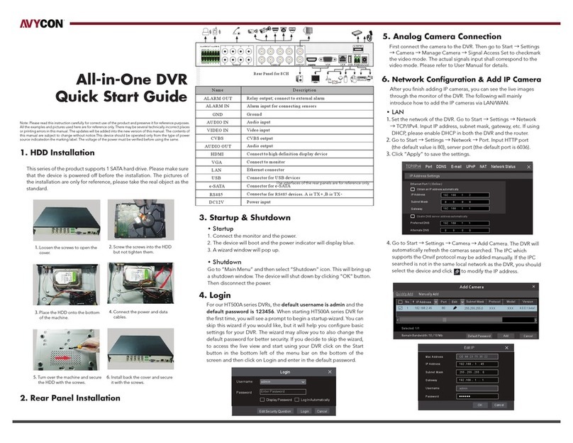
This series of products supports 1 x SATA hard drive. Plese make sure the
device is powered off before the installation. The pictures of the installa-
tion are only for reference.
①Loosen the screws to open the cover.
②
③
④
⑤
Screw the screws into the HDD, but don’t tighten them.
Place the HDD onto the bottom of the machine.
Turn over the machine and sequre the HDD with the screws.
Connect the power and data cables.
⑥Install the cover back on and secure it with screws.
TIP: Please check the inside structure of the device and make sure the
cables are connected well before installing the back cover.
4. REAR PANEL INSTRUCTION
The interface of the panel is for reference only.
5. STARTUP & SHUTDOWN
DC48V
Name
POE PORTS
LAN
USB
VGA
HDMI
AUDIO OUT
AUDIO IN
P / Z
K /B
GND & ALARM IN
ALARM OUT
Connector for power input
Description
8 PoE network ports; connect to PoE IP cameras / panels
Ethernet port
Connectors for USB devices (like USB mouse, USB storage
device for backup or upgrade, etc. )
Connect to monitor
Connect to high definition display device
Audio output
Audio input
Connector for a PTZ device. Y is TX+, Z is TX-
Connector for a keyboard. A is TX+, B is TX-
Connectors for alarm input devices, like sensors
Relay output; connectors for external alarm output devices
①Connect the monitor and the power.
②
③

The device will boot and the power indicator will display blue.
A wizard window will pop up.
› Startup
› Shutdown
Click “Start” and select “Shutdown” icon. This will bring up a shutdown
window. The device will shut down by clicking “OK” button. Then
disconnect the power.
6. LOGIN
You must configure the wizard if you start the NVR for the first time.
Choose the language and read the privacy statement. Then set the data,
time and zone as needed. After that, set the login password.
Username
Admin Password Setup
New Password
Confirm Password
Pattern Lock
admin
Wizard
123456
123456
Display Password
Enable
Log In Automatically
NextPrevious
Edit
The default username is admin and the default password of admin is
123456. Set your own password or use the default one when you use the
wizard for the first time. Enable pattern lock and click “Edit” to set the
pattern lock. Then set security questions and answers. It is important for
you to remember these answers, or you will not be able to reset your
password. Click “Next” to continue.
7. DISK SETTINGS
You must configure the wizard if you start the NVR for the first time.
Choose the language and read the privacy statement. Then set the data,
time and zone as needed. After that, set the login password.
8. NETWORK CONFIGURATION &
ADD DEVICES
①Enter IP address, subnet mask, gateway, etc. If using DHCP, please enable
DNCHP in both the NVR and the router.
②
③

Enter HTTP port (the default value is 80) and server port (the default port
is 6036).
The internal ethernet port is the port which connects all the PoE ports
with the NVR system. The PoE ports are available if the internal ethernet
port is online; if is offline, all the PoE ports will be unavailable.
Wizard
Obtain an IP ad dr es s au to ma ti ca ll y
Internal Ethernet Port ( Online )
Address Address
192 . 1 68 . 1 . 2
. . .255 255 2 55 0
192 . 1 68 . 1 . 1
Subnet Mask
Gateway
Subnet Mask
Ethernet Port 1 ( Online )
Obtain DNS automatically
HTTP Port RTS P Po rt
HTTPS Port Sever Port
. . .
. . .
Preferred DNS
Alternate DNS
8 0
443
Network Settings
10 . 151 . 1 51 . 1
. . .255 255 255 0
NextPreviou s Cancel
6036
554
④Add camera. Click “Next” to go to the following interface.

80
80
80
No. Ad dress Edi t Port Proto col
1
2
3
192. 168.1.2 0
192. 168.1.3 8
192. 168.2.4 5
XXX
XXX
XXX
Wizard
Network Settings Ad d Camera
No. Address
IP Cam era N am e Prot ocol
1
10.151.151.103
[POE 1] IPC
Add All
Refresh
Remain Bandwidth: 77 / 80 Mb
Faci al Pane l
5.0.2.0
5.0.1.0
5.0.2.0
Versi on Add
+_
_
_
+
+
Mode l
XXX
XXX
XXX
Dele te
Edit
Stat us
Onli ne
Dele te All
9. RECORD SETTINGS
Click “Refresh” to refresh the list of online IP cameras / panels which
are in the same local network with the device. Click + to add the
searched cameras / panels. Click “Add All” to add all the devices in
the list.
Two record modes: auto and manual.
Auto mode: Select one auto mode in the interface as shown below
and then click “Next to save the settings. Click ”Advanced” to self-de-
fine a record mode.
Wizard
Mode
Motion Record
Sensor Record
Motion Record+Sensor Record
Always(24x7)Record+Motion Record
Always(24x7)Record+Sensor Record
Always(24x7)Record+Motion Record+Sensor Record
Always(24x7)Record+Motion Record+Sensor Record+Analytics Record
Next
Advanced
Previous Cancel
Record Settings
Network Settings Add Camera Disk Settings
Auto
Manual: Set the “Sensor Record”, “Motion Record”, “Analytic
Record” and “Schedule Record” of each camera. Please enable the
record as needed. Click “Next” to continue.
10. NAT
You can enable the NAT function in the interface or set in the network
configuration after exiting the wizard. You can scan the QR code
through the mobile surveillance APP for IOS or Android to easily view
your camera.
› Web Client Access Through NAT Function
d2yt.natplus.top:7968
NAT Server Address
Enable
Visit Address www.natplus.top
Apply
NAT
NAT Status Success
Enter www.natplus.org in the address bar of your browser and then
press enter to go to the following interface. If you are the first time to
access the NAT, you shall download and install the plug-in according
to the popup tips. After that, the login box will be displayed.
Ente r Pas sword
Ente r Use rname
Ente r dev ice ser ial number
Login
Click on the menu bar at the bottom of the live interface to
check the serial number.
The login username of the device.
The login password of the device.
11. ADD CAMERAS
Click Start > Settings > Camera to go to the “Edit Camera” interface.
Click “Add” to add cameras.
9008
9008
9008
No. Address Port Subnet Mask
1
2
3
192.168.1.20
192.168.1.38
192.168.2.45
255.255.0.0
255.255.0.0
255.255.0.0
Add Camera
Attendance Terminal
Cancel
Facial Pan el
Default password management
Terminal Type
5.0.2.0
5.0.1.0
5.0.2.0
Version Serial No.
_
_
_
Model
XXX
XXX
XXX
Facial IPC IP Camera
Test Add
Add and Continue
00:18 :AE :56 :xx:xx
?
Address Port
Domain
Device Name Protocol
192 . 16 8 . 1 . 2 0
Username Password
Default Password
Please enter the camera n...
IP Camera
admin
Select an IP camera / panel and then choose the terminal type as
needed. Then enter device name and password and click “Add” to
add devices.
IP Panel: Four terminal types can be selectable. Facial panel or
attendance terminal is suggested.
Facial IPC: The IPC which supports face recognition can choose this
one.
12. PEOPLE MANAGEMENT
Click Start > People Management to go to the people management
interface.
1. Click and then set the company name, department and position of people.
2. Add face pictures and relevant information for each group.
Select a group and then click “Add” to go to the following interface.
Click “Select face” to choose a face from snapshot gallery or external faces.
Fill out the other information (like attendance area, pass through area) and
then click “Entry”.
Multiple face pictures can be added from “External faces” too. Put pictures and the file of personal
information under the same directory of your mobile storage device. Select this directory and click
“Full Entry” to add. Edit the file as follows.
Note: Currently, only when the face picture is added to the face database and successfully
matched by the IP Panel, can the Smart Management Terminal (SMT) show the temperature and
picture of the person.
13. LIVE DISPLAY
Start
Camera
Real-Time Warning
Statistical information view, including over temperature counts,
non-mask detection counts, attendance statistics,
personnel records
Area 1: Real-time statistical information display
Area 2: Real-time intelligent detection information display, including
face match, body temperature, mask status, area, etc.
Area 3: Real-time face capture and temperature measurement display
14. ATTENDANCE SETTINGS & SEARCH
1. Click Start >Attendance >Rule Settings to go to the rule setting
interface. Set the working start and end time, “Late” and “leave early”
rules, working day and holiday. Click a date on the calendar to switch
between working day and holiday. Then click “Save” to save the settings.
2. Leave and Business Trip Settings: Go to the Leave and Business Trip
interface and then click “Add” to pop up a window. Click “Add” to add the
person who wants to ask for leave or a business trip and then set the start
and end time.
3. Attendance Search: Set the filter condition, like attedance date,
attendance area, etc. Then click “Search” to search the attendance
information of staff. Select a person click to view the detailed attedance
information of this person.
15. PASS-THROUGH RECORDS SEARCH
Click Start > Search and Backup > Pass-Through Records to go to the
following interface.
1.Select date, camera, event
(like allow list, block list)
and attribution (including mask
on/off, temperature status)
as needed.
2.Click “Search” to
search the pass-through
records
In this interfa ce, the captured face pictures and records list
face match pictures can be displayed and pictures and records can
be exported.
Playback button
Click the captured picture to see the snapshot details

Other AVYCON DVR manuals

AVYCON T900 Series User manual

AVYCON

AVYCON T900 Series User manual

AVYCON DIVERSITY Series User manual

AVYCON

AVYCON DIVERSITY Series User manual

AVYCON AVR-T908A-4T User manual

AVYCON

AVYCON AVR-T908A-4T User manual

AVYCON AVR-P704 User manual

AVYCON

AVYCON AVR-P704 User manual

AVYCON AVR HT Series User manual

AVYCON

AVYCON AVR HT Series User manual

AVYCON AVR-T908A-1T User manual

AVYCON

AVYCON AVR-T908A-1T User manual

AVYCON HT800A Series User manual

AVYCON

AVYCON HT800A Series User manual

AVYCON AVR-HT504A-1T User manual

AVYCON

AVYCON AVR-HT504A-1T User manual

AVYCON H5300 series User manual

AVYCON

AVYCON H5300 series User manual

AVYCON AVR-TS504A User manual

AVYCON

AVYCON AVR-TS504A User manual

AVYCON AVR-NT504A User manual

AVYCON

AVYCON AVR-NT504A User manual

AVYCON T900 User manual

AVYCON

AVYCON T900 User manual

AVYCON AVR-NT504A User manual

AVYCON

AVYCON AVR-NT504A User manual

AVYCON AVR-HT832A-40T User manual

AVYCON

AVYCON AVR-HT832A-40T User manual

AVYCON DIVERSITY User manual

AVYCON

AVYCON DIVERSITY User manual

AVYCON AVK-TL91E4-1T User manual

AVYCON

AVYCON AVK-TL91E4-1T User manual

Popular DVR manuals by other brands

XENO Nitro XHDAR quick start guide

XENO

XENO Nitro XHDAR quick start guide

Sanyo DSR-3000 instruction manual

Sanyo

Sanyo DSR-3000 instruction manual

Uniden UNVR85-4 user guide

Uniden

Uniden UNVR85-4 user guide

Mitsubishi Electric DX-TL5716U Specifications

Mitsubishi Electric

Mitsubishi Electric DX-TL5716U Specifications

REI HD5 Care and maintenance quick guide

REI

REI HD5 Care and maintenance quick guide

EverFocus ECOR264-D2 DVR Series user manual

EverFocus

EverFocus ECOR264-D2 DVR Series user manual

TechVision PDVR-S4L15 manual

TechVision

TechVision PDVR-S4L15 manual

Samsung SHR-5082-250 user manual

Samsung

Samsung SHR-5082-250 user manual

Swann DVR4-1200 user manual

Swann

Swann DVR4-1200 user manual

Digital Watchdog Blackjack CX DW-BJCX8T-LX quick start guide

Digital Watchdog

Digital Watchdog Blackjack CX DW-BJCX8T-LX quick start guide

Law Enforcement Associates 99520K manual

Law Enforcement Associates

Law Enforcement Associates 99520K manual

Epcom S04 S Series user manual

Epcom

Epcom S04 S Series user manual

CPcam CPD500W quick start guide

CPcam

CPcam CPD500W quick start guide

Footprint Security H.264 user manual

Footprint Security

Footprint Security H.264 user manual

CP Plus Indigo manual

CP Plus

CP Plus Indigo manual

Samsung SRD-850DC Technical specifications

Samsung

Samsung SRD-850DC Technical specifications

Lorex LH330 Edge2 Series instruction manual

Lorex

Lorex LH330 Edge2 Series instruction manual

SONIQ QMR600X instruction manual

SONIQ

SONIQ QMR600X instruction manual

manuals.online logo
manuals.online logoBrands
  • About & Mission
  • Contact us
  • Privacy Policy
  • Terms and Conditions

Copyright 2025 Manuals.Online. All Rights Reserved.