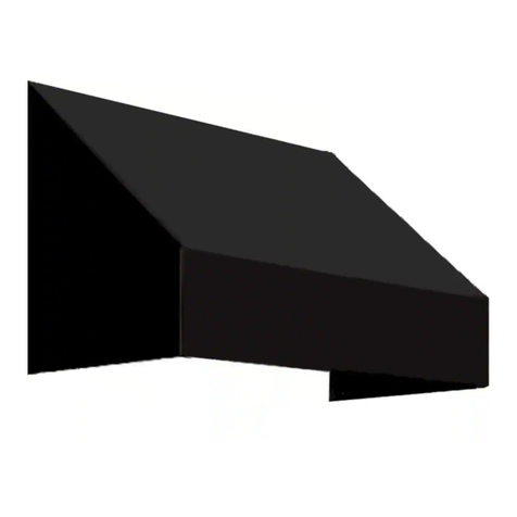
Awntech BAHAMA Original instructions

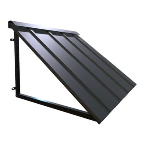
BAHAMA ALUMNINUM SHUTTER STYLE AWNING
OWNER’S MANUAL & INSTALLATION INSTRUCTIONS (For 5ft, 6ft, 7ft, & 8 ft
W dths)
Contents
ATTENTION: Warning Statement .................................................................................................... 2
Hardware for different surface applications ..................................................................................... 2
Parts List ..........................................................................................................................................
Parts Included:..............................................................................................................................
Assembly for 5ft, 6ft, 7ft, and 8ft Width Bahama Awnings............................................................... 5
Count every part for your specific width and projection............................................................... 5
Step 1: Assembling the (b ) Full Top Bar and (c ) Full Front Bar ............................................... 5
Step 2: Assembling ¾ of the Bahama Frame .............................................................................. 6
Step : Installing the (e)/(e2) Middle Support(s) to the (b ) Full Top Bar .................................... 7
Step 4: Assembling the Shutters.................................................................................................. 8
Step 5: Assemble Shutters onto the Complete Frame............................................................... 10
Step 6: Installing the (c ) Front Bar to the (d1/d2) Left/Right Frame, and the Middle Supports.
.................................................................................................................................................... 11
Step 7: Installing the Shutters to the (d1/d2) Left/Right Frame, (e) Middle Support, and (e2)
Center Middle Support ............................................................................................................... 12
Step 8: Attaching the (m) Projection Arms to the (d1/d2) Left/Right Frame .............................. 1
Step 9: Attaching the (q) Top Bar Bracket to the (b) Top Bar and Mounting.............................. 14
Step 10: Attaching the (m) Projection Arms to the Surface ....................................................... 15
Step 11: Your Finished Bahama Awning! ................................................................................... 15

Page | 2
ATTENTION: Warning Statement
Warning: Adult assembly required
Warning: Assembly kit contains parts with sharp points, sharp edges, and small parts that can
present choking hazards to children.
Warning: Components are packed in plastic bags that are a suffocation hazard.
NOTE: Please inspect the parts for damage during shipping and/or for any missing items. If you suspect
that there may be damage or a shortage, contact us and we will send replacement parts if needed. At
this time, visualize how the components fit together and make sure that you have identified the various
parts.
Hardware for different surface applications
Prior to assembly, please take a moment to understand the type of mounting surface you are working
with. There are a variety of installation surfaces as shown in the table below. Given the wide variety
of mounting surfaces, please be aware that Awntech does not supply mounting hardware. You will
need to purchase installation hardware at your local hardware store. We recommend the following
hardware for different installation applications:
CONCRETE BLOCK WALLS:
¼
” x 3” Masonry anchor bolts or Tapcon Screws plus Washers (1 per
bracket)
WOOD OR SIDING:
¼
” x 3” Lag Screws plus Washers (1 per bracket)
OTHER STRUCTURES: CONSULT A PROFESSIONAL
parts.

Page |
Parts List
Parts Included:

Page | 4

Page | 5
Assembly for 5ft, 6ft, 7ft, and 8ft W dth Bahama Awn ngs
For video assistance on our Bahama Awning assembly, please navigate to our
YouTube page at: https://youtu.be/b5KOY-8TVUI
Count every part for your specific width and projection
Step 1: Assembling the (b ) Full Top Bar and (c ) Full Front Bar
1a) (b ) Full Top Bar Assembly. Refer to Figure A1.1
i. Gather your 1-(b1) Top Bar, 1-(b2) Top Bar,
1-(g) Aluminum Bar Connector, and 8-(L)
Sheet Screws.
ii. Insert ½ of the (g) Aluminum Bar Connector
inside the (b1) Top Bar by gently tapping the
connector with a rubber mallet.
iii. Connect the flat end of the (b2) Top Bar to
the other ½ of the same (g) Aluminum Bar
Connector by using a rubber mallet and
gentle tapping the angled end of the (b2) Top
Bar.
iv. Install 8-(L) Sheet Screws on the Full Top Bar.
F gure A1.1: (b3) Full Top Bar Assembly
1b) (c ) Full Top Bar Assembly. Refer to Figure A1.2
i. Gather your 1-(c1) Front Bar, 1-(c2) Front Bar,
1-(g) Aluminum Bar Connector, and 8-(L)
Sheet Screws
ii. Insert ½ of the (g) Aluminum Bar Connector
inside the (c1) Front Bar by gently tapping the
connector with a rubber mallet
iii. Connect the flat end of the (c2) Front Bar to
the other ½ of the same (g) Aluminum Bar
Connector by using a rubber mallet and
gentle tapping the angled end of the (c2) Top
Bar.
iv. Install 8-(L) Sheet Screws on the (c ) Full
Front Bar to secure the (g) Aluminum Bar
Connectors to the frame.
F gure A1.2: (c3) Full Front Bar Assembly

Page | 6
Step 2: Assembl ng ¾ of the Bahama Frame
2a) Positioning the Frame Parts Before Installation (The backside of each frame part should face
upwards in this entire step)
i. Place the (d1) Left Frame and (d2) Right Frame parallel to each other. The pre-drilled holes
should be furthest from top bar when installed. Refer to Figure A2.1 – Back of the Awning
ii. Insert (a) Black Nylon “L” connectors into the ends of the (b ) Full Top Bar.
iii. Connect the (d1) Left Frame and (d2) Right Frame ends to the (b ) Full Top Bar by using
a rubber mallet/hammer.
iv. Install 2-(L) Sheet Screws on both corners of the frame to secure (d1), (d2), and (b ) to the
(a) Black Nylon “L” Connectors. Refer to Figure A2.2
F gure A2.1: Positioning the Frame Parts for Installation
F gure A2.2: Installing (L) Sheet Screws each corner of the frame

Page | 7
Step : Installing the (e)/(e2) Middle Support(s) to the (b ) Full Top Bar
3a) Installation for 5ft Widths: Refer to Figure A3.1
i. Turn the ¾ Frame over to the front side.
Refer to Figure A1.1
ii. Use 1-(L) Sheet Screw to install the top of
the 1-(f) Middle Support Connector to the pre
drilled hole on the inside of the (b ) Full Top
Bar
iii. Insert one open end of the 1-(e2) Center
Middle Support around the prongs of the 1-
(f) Middle Support Connector that is now
attached to the (b ) Full Top Bar.
iv. Align the pre drilled holes at the end of the
(e2) Center Middle Support with the pre
drilled holes on the prongs of the 1- (f) Middle
Support Connector.
v. Install 2-(L) Sheet Screws on the top and
bottom of both ends of the (e2) Center
Middle Support.
F gure A3.1: Installing the (f) iddle Support
Connectors and the (e) iddle Support for 5ft
Widths
3b) Installation for 6, 7, and 8ft Widths: Refer to
Figure A3.2
i. Attach the top of -(f) Middle Support
Connectors to the pre drilled holes on the
inside of the (b ) Full Top Bar with -(L) Sheet
Screws.
ii. Lay out the 1-(e2) Center Middle Support and
place the 2-(e) Middle Supports on either side
of the (e2) Center Middle Support. The (e2)
Center Middle Support will have 4 pre-drilled
holes. When installing, face the pre-drilled
holes towards the backside of the awning and
furthest away from the (b ) Full Top Bar. (The
projection arm will be attached to this (e2)
Center Middle Support)
iii. Attach one open end of both (e) Middle
Supports and the (e2) Center Middle Support
to an (f) Middle Support Connector on the (b )
Full Top Bar. (Make sure the pre drilled holes
on the prongs of the (f) Middle Support
Connectors align with the pre drilled holes on
the top and bottom of the (e) Middle
Supports.)
iv. Install 2-(L) Sheet Screws on the top and
bottom of one side of the (e) Middle Supports
and (e2) Center Middle Supports into the
prongs of the (f) Middle Support Connectors.
F gure A3.2: Installing the (f) Middle Support
Connectors and the (e) Middle Supports and
(e2) Center Middle Support for 6, 7, and 8ft
Widths
Page | 8
Step 4: Assembling the Shutters
For additional instruction here, please refer to the Bahama Assembly link on
YouTube: https://youtu.be/b5KOY-8TVUI
4a) Assembling One Set of Shutters
i. Determine the amount of (i) Shutter Slats for one Shutter Set
ii. Attach the right side of each (i) Shutter Slats in to an individual “Slit” on 1-(h) Louver l-
Frame. The (i) Shutter Slats should be assembled with the smooth side on top and facing
at a downward angle towards. (if the slats don’t connect easily, try using a rubber mallet to
tap them into the “slits”)
iii. Secure Shutter Slates to the (h) Louver l-Frame with (k) Right Shutter Slat Mounting Braces.
Refer to A4.2 on how to install the braces.
iv. Once the (k) Right Shutter Slat Mounting braces are attached, continue step ii) & iii) to
assemble the left side of the Shutter Slats to the 2nd (h) Louver l-Frame. (be sure to use
the (j) Left Shutter Slat Braces for the left side installation.
4b) Repeat steps i) through iv) in order to assemble the additional shutter sets depending on the size
width.
**At this point, you should have assembled two or four sets of shutters. There are no differences in
these sets. **

Page | 9
F gure A4.1: Inserting the (i) Shutter Slats into (h) Louver I-frames.
Figure A4.2: Inserting the (j) Left Shutter Slat ounting Braces and (k) Right Shutter Slat ounting
Braces
How To: Insert the Shutter Slat Braces
1. Put Shutter Sets side by side with the smooth side facing upward
and at a downward angle.
2. Locate the right side of the shutter and insert the “U” Shape part
of the (k) right Shutter Slat Mounting Braces directly into the right
side “slit” that is between the (h) Louver l-Frame and the (i) Shutter
Slats. (The “U” Shape should lay flat against the (h) Louver l-
Frame when inserting it in and that the braces are installed in the
same direction).
3. Once inserted, push down the extenders of the (k) Left Shutter
Slat Mounting Braces so that they are lying against the (h) Louver
l-Frame. This will secure the (h) Louver l-Frame with each (i)
Shutter Slat.
4. Repeat this with the (j) Left Shutter Slat Mounting Braces

Page | 10
Step 5: Assemble Shutters onto the Complete Frame
5a) Insert the First Set of Shutters into the ¾ assembled frame
i. Ensure that the ¾ frame is oriented so that the (b) Top Bar is furthest from you
ii. Ensure that the first Shutter Set is oriented where the slats point downwards towards you
iii. Place the Shutter or slide it upwards in between the grooves of the Middle Supports and
the Left and Right Frames.
iv. Repeat the same steps for each shutter.
F gure A5.1: Inserting Shutters into ¾ Frame

Page | 11
Step 6: Installing the (c ) Front Bar to the (d1/d2) Left/Right Frame, and the
Middle Supports.
6a) Installing the (c ) Full Front bar to the ¾ assembled Frame
i. Attach 2 (a) Black Nylon “L” Connectors to the ends of the (c ) Full Front Bar.
ii. Attach the top of the (f) Middle Support Connectors to the pre-drilled hole on inside of the
(c ) Full Front Bar and installing with 1-(l) Sheet Screw each.
iii. Connect both ends of the (c ) Full Front Bar to the (d1) and (d2) Left and Right Frame with
a Rubber Mallet
iv. The (f) Middle Support connector should attach to the middle support. Be sure the pre-
drilled holes on the tongs on the (f) Middle Support are aligned with the pre-drilled holes
on the (e) Middle Support ends and (e2) Center Middle Support ends (for 6-8ft widths).
v. Install the (l) Sheet Screws into the pre-drilled holes located on the corners of the (d1) Left
Frame, (d2) Right Frame, (c) Front Bar, and (f) Middle Support connectors.
F gure A6.1: Attaching (c3) Full Front Bar to the (d1) and (d2) Left and Right Frame and the (f) iddle
Support Connectors

Page | 12
Step 7: Installing the Shutters to the (d1/d2) Left/Right Frame, (e) Middle
Support, and (e2) Center Middle Support
7a) Installing the Shutter Sets to the (d1) and (d2) Left and Right Frame and (e) Middle Support
i. Be sure the Shutter Slats are evenly lined up with each other and also between the grooves
of the (d1) and (d2) Left and Right Frame and (e) Middle Support.
ii. Locate the 6 pre-drilled holes on the (h) Louver l-Frame on each shutter set. Install sheet
screws into each pre-drilled hole to install the Shutter sets to the awning. (There are no
pre-drilled holes on the inside of the frame. More force will need to be used when drilling
into the frames metal)
F gure A7.1: Installing a Shutter Set to the inside of the frame

Page | 1
Step 8: Attaching the (m) Projection Arms to the (d1/d2) Left/Right Frame
8a) Attaching the (m) Projection Arms to the (d1) Left Frame, (d2) Right Frame, and (e2) Center
Middle Support
i. Flip the awning back over to view the backside of the awning (Refer to Figure A1.1)
ii. Line up the four holes on the plate of the (n) Frame/Wall Bracket, to the four holes on the
back of the (d1) Left Frame, (d2) Right Frame, and (e2) Center Middle Support.
iii. Tighten the (x) Short Bracket Screws into each hole to fasten the (n) Frame/Wall Brackets.
iv. Attach one side of the (m) Projection Arms to the larger holes on the installed (n)
Frame/Wall Bracket. Feed the (r) Bolt through the holes and tighten it with the (t) nut.
8b) Repeat steps i) through iv) for the other (m) Projection arms.
i. Install the last two (n) Frame/Wall Brackets to the ends of the (m) Projection Arms
ii. Line up the hole at the end of 1-(m) Projection arm with the holes of 1-(n) Frame/Wall
Bracket and thread 1-(r) Bolt through. Tighten with 1-(t) Nut.
iii. Repeat this step for the other projection arms.
F gure A8.1: Attaching (m) Projection Arms to the (d1) Left Frame, (d2) Right Frame, and (e2) Center
iddle Support

Page | 14
Step 9: Attaching the (q) Top Bar Bracket to the (b) Top Bar and Mounting
9a) Installing the (q) Top Bar Bracket to the Back of the (b) Top Bar
i. Line up the two holes of the smaller half of the (q) Top Bar Bracket to one the set of holes
on the back side of the (b) Top Bar. The larger half of the bracket will be installed up against
the wall.
ii. Secure the (q) Top Bar Bracket to the (b) Top Bar by inserting and tightening 2-(x) Short
Bracket Screws.
iii. Repeat steps a) and b) for the remaining (q) Top Bar Bracket
9b) Mount the top bar bracket to the surface
i. Once you have determined where you want to mount the awning, have one person hold
up the awning against the wall (parallel with the ground) and the other person mount the
(q) Top Bar Bracket to the wall. Once the (q) Top Bar Brackets are installed, slowly lower
the awning. (Refer to Figure A9.1)
F gure A9.1: Attaching the (q) Top Bar Bracket to
the (b ) Top Bar
F gure A9.2: Mounting (q) Top Bar Bracket to the
Surface

Page | 15
Step 10: Attaching the (m) Projection Arms to the Surface
10a) Once the (m) projection arms are attached, plate of the (n) Wall Bracket against your surface and
mount it with the specified hardware for your surface. Refer to Figure A10
F gure A10.1: Install the (n) Wall Bracket to the (m) Projection Arms and to the Wall
Step 11: Your Finished Bahama Awning!
F gure A11.1: Final Installation

Page | 16
WARRANTY
5-Year Manufacturer's Limited Warranty
Obtaining necessary permits is the sole responsibility of the purchaser.
Purchaser/customer agrees he/she/company will NOT hold Awntech liable for improper installation, maintenance
and repairs.
A. WARRANTY:
5 Year Limited Manufacturer’s Warranty (Prorated by the month)
B. WHO GIVES THIS WARRANTY?
Awntech Corporation, 10950 S. Pipeline Road, Euless, TX 76040
C. WHO IS ENTITLED TO THIS WARRANTY?
This Warranty applies only to the original purchaser who paid for the product and may not be assigned or
transferred to subsequent owners. This Warranty applies only to products purchased and installed in the United
States.
D. WHAT ARE THE RESPONSIBILITIES OF AWNTECH UNDER THIS WARRANTY?
Subject to the terms and conditions set forth herein, Awntech Corporation will furnish replacements for parts
found by Awntech Corporation to be defective in design, manufacture or assembly, under each specific
component or product warranty as set forth below.
E. WHAT ARE THE RESPONSIBILITIES OF THE ORIGINAL PURCHASER UNDER THE WARRANTY?
•Before any claims may be made under this Warranty, the original purchaser must have paid in full for
the product covered under the Warranty, according to the terms and conditions of the pay-plan defined
in the original order. IF THE PURCHASER HAS FAILED TO MAKE FULL PAYMENT, THIS
WARRANTY SHALL BE NULLIFIED AND AWNTECH CORPORATION SHALL BE RELIEVED FROM
ANY RESPONSIBILITY OR LIABILITY UNDER THIS WARRANTY. The purchaser agrees and
acknowledges that this Warranty agreement constitutes an executor contract.
•The purchaser must use care in installation, maintenance, operation, use, and storage of the product in
accordance with the instructions contained in the owner’s manual. ANY FAILURE TO INSTALL,
MAINTAIN, OPERATE, USE AND STORE THE PRODUCT IN ACCORDANCE WITH THE
INSTRUCTIONS CONTAINED IN THE OWNER’S MANUAL WILL NULLIFY THIS WARRANTY AND
RELIEVE AWNTECH CORPORATION FROM ANY RESPONSIBILITY OR LIABILITY UNDER THIS
WARRANTY.
•Promptly notify Awntech Corporation of any claims.
•At Awntech’ s request the purchaser may be required to provide a photographs or videos (if necessary)
of any defective parts. The purchaser may also be required to pay a deposit until the defective parts are
returned to Awntech Corporation for inspection. The purchaser must obtain a return authorization form
from Awntech Corporation’s customer service department prior to the return of any merchandise and
after having received such authorization, return the part or product, freight prepaid, to Awntech
Corporation.
F. WHAT IS COVERED UNDER THIS WARRANTY?
The following components of Awntech® models and their accessories (defined as accessories attached to the
awning) are covered under this Warranty, subject to the limitations set forth below. These components have a
five (5) year limited (prorated) warranty, against manufacturer’s defects as outlined below:
a) Should the purchaser promptly notify Awntech Corporation of such defects within one year (12 months)
from the date of the original purchase, the defective component will be replaced at no charge to the

Page | 17
purchaser. Awntech reserves the right to ask for the defective part to be returned and/or photos/videos
of the defective part.
b) b) After one year but within five years (60 months) from the date of the original purchase, a defective
component will be replaced upon the purchaser's payment of 1/60th of the full retail cost of the
component for each month of use prior to the claim.
FIXED AWNINGS – COVERED COMPONENTS
All the components warranted not to fail for five (5) years prorated.
G. WHAT IS NOT COVERED UNDER THIS WARRANTY?
•Any failure or damage of the components that results from any intentional or negligent actions by the
purchaser or by any other person is not covered by this Warranty.
•It is the responsibility of the purchaser to securely fasten the awning to studs, joists, headers or other
structural members. Any failure or damage that results from the awning falling from its installed position
is not covered by this Warranty.
•Labor charges connected with installation of replacement parts are not covered by this Warranty.
•Freight expenses to and from Awntech Corporation are not covered by this Warranty and must be paid
by the purchaser.
•A bottle of touch up paint is included with each awning. It is the responsibility of the purchaser to
inspect their awning for scratches or exposed metal. It is the responsibility of the purchaser to liberally
apply touchup paint to any identified areas during their inspection for scratches or exposed metal.
Ignoring scratches or exposed metal will allow for corrosion or rust in the afflicted areas.
H. GENERAL PROVISIONS AND LIMITATIONS
•The warranty granted herein is the exclusive remedy for the purchaser. Awntech Corporation makes no
other warranties to the purchaser, express, statutory, implied or otherwise and all implied warranties,
including without limitations, implied warranties of merchantability and fitness for a particular purpose,
are hereby disclaimed.
•To the extent permitted by law, Awntech Corporation shall have no liability to the purchaser or any other
person for incidental, special, consequential, indirect or similar damages of any kind or nature
whatsoever, whether arising out of breach of warranty or other breach of contract, negligence or other
tort, or otherwise, even if Awntech Corporation shall have been advised of the possibility or likelihood of
such potential loss or damage. In no event shall Awntech Corporation be liable for loss of profits and/or
wages.
•Some states do not allow limitations on how long an implied warranty lasts, or do not allow the exclusion
or limitation of incidental or consequential damages, so the above limitations may not apply to you.
This warranty gives you specific rights, and you may have other rights, which vary from state to state.
Awntech Corporation, 10950 S. Pipeline Rd., Bldg. 1, Euless, TX 76040 / Ph 817-354-9600; Fax 817-

Page | 18
RETURNS & DAMAGES
RETURN QUALIFICATION:
You can only return a product if it is defective upon arrival. If you simply do not like the product or if you did not
measure correctly, you will only be qualified for a merchandise credit and you will be required to pay for shipping
the product back to Awntech in re-stock condition. There will be a 25% restock fee applicable. Concealed
damage must be reported within 7 days from the receipt of the awning.
DAMAGED MATERIAL:
Damage occasionally occurs during shipping. Scrapes dents and rips in the outer packaging that could indicate
possible damage should be described to the carrier at the time of delivery. If damage to the product seems
apparent, the shipment should be refused.
RETURNS/ORDER EXCEPTIONS:
REPAIR AUTHORIZATION NUMBER YOU MUST GO THROUGH THE WARRANTY PROCESS: E-mail Photos
of damaged parts to: w[email protected] or mail to: Awntech Corporation, 10950 S. Pipeline Rd., Bldg 1,
Euless, TX 76040
Authorized returns should be shipped to:
Returns Department: Awntech Corporation, 10950 S. Pipeline Rd., Bldg 1, Euless, TX 76040
Table of contents
Other Awntech Accessories manuals

Awntech
Awntech Chicago RC22 Safety guide

Awntech
Awntech CH21 Original instructions

Awntech
Awntech Full Cassette User manual

Awntech
Awntech Dallas Retro RR22 Original instructions

Awntech
Awntech Houstonian Original instructions

Awntech
Awntech RN22 Original instructions

Awntech
Awntech NO21 Original instructions

Awntech
Awntech RF22 Original instructions

Awntech
Awntech Dallas Retro RR22 Original instructions

Awntech
Awntech Savannah Original instructions