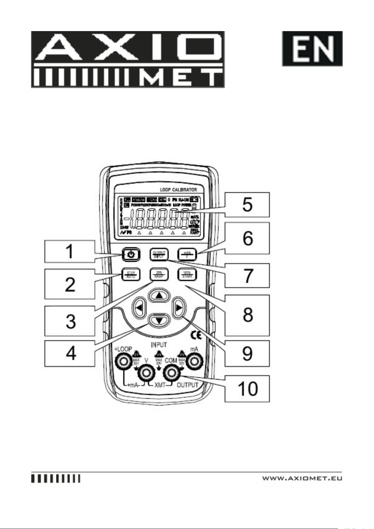
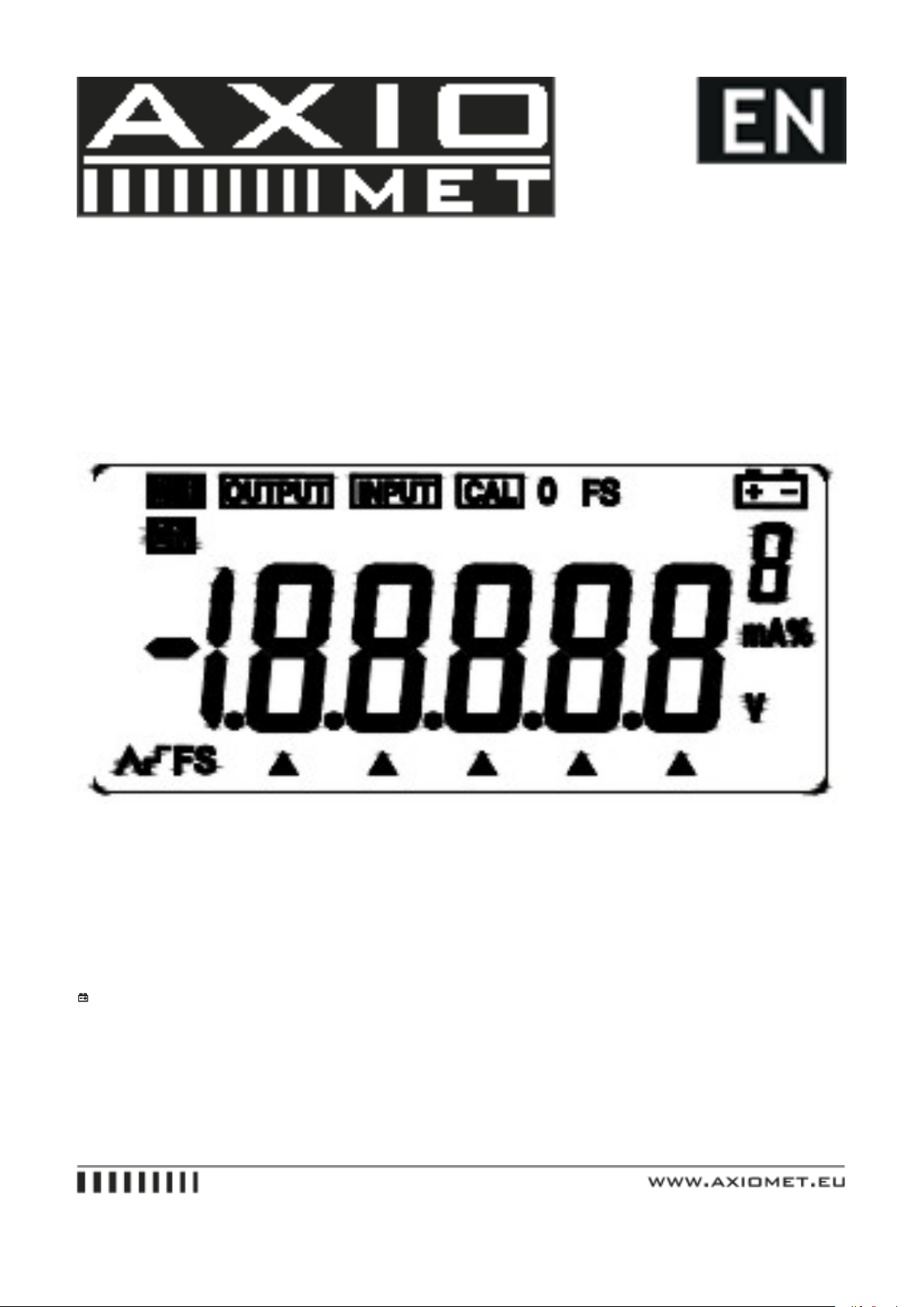
• When the key �OUTPUT/IN �is pressed, the OUTPUT appears in the LCD, it denotes the Instrument is in an output
state
• When the key �STEP/AUTO �is pressed, the symbols ’OUTPUT’, ’OFF’, ’^S’ appear in the LCD. If so, it denotes
that the Instrument is getting into the mode of RAMP
• Repress the key �25%/RAMP�again so as to change the type of the output ramp, which finds itself in the lower left
of the LCD. The type appears with ’^S’,’^F’ in proper order. These symbols denote a low speed ramp and a high
speed ramp respectively. The former is set to a cycle up to 60S and the latter is up to 30S, while the auto-stair step
ramp pauses 5 seconds at each step
• Press the key�100%/START�to start the output of the set waveform when the symbol ‘ON’ appears. Now repress
the key�100%/START�again and the output will pause on a current value and the symbol ‘OFF’ will appear. Then
press the same key again and the output will continue to do the set steps from the pause value. When the symbol
‘OFF’ appears, press any one of the keys�LEFT�,�RIGHT�,�UP�,�DOWN� so as to bring the output back to
the 0%. Then the value of 4mA appears in the display.
5.6. Simulating Transmitter Output (XMT)
• Insert one end of the test lead to the ‘XMT’ output jack of the Instrument and connect the other end with the input
terminal of the user’s device
• The key-operation is the same as that of the current output.
Note
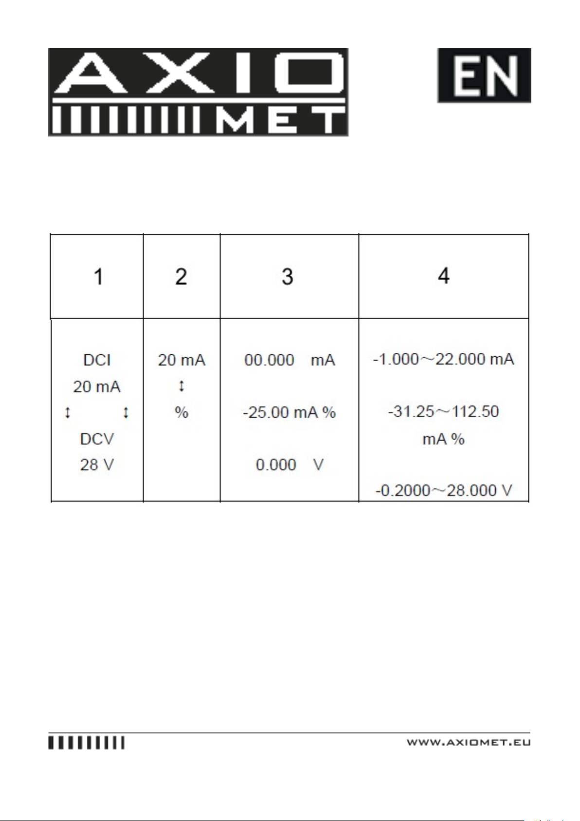
• Range of power supply: 5 to 25VDC.
• Usage: during the operation of the current output, use the external 24VDC power supply in a mode of connecting a
transmitter, thus being able to prolong the working life of the battery.
6. Instrument Measurement
6.1.
Warning
During the operation, never apply more than 30V between any two terminals, or between any terminal and earth ground.
Any voltage more than 30V will not only do damage to the Instrument, but also lead to possible personal injury.
Caution!
• During the operation, do not apply a voltage or current exceeding the measuring range to the input terminal, which
will cause possible damage to the Instrument.
• When connecting to the Instrument, the power supply of the device under test should be cut off. Otherwise, any
connection with a device without cutting off its power supply will cause possible damage to the Instrument.