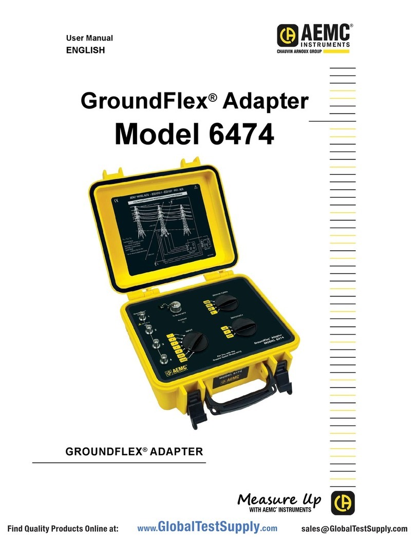
AEMC instruments 6470 User manual

DIGITAL GROUND
RESISTANCE AND SOIL
RESISTIVITY TESTER
ENGLISH User Manual
6470

Owner’s Record
The serial number for the Model 6470 is located on the instrument’s case. Please
record this number and purchase date for your records.
GROUND RESISTANCE TESTER MODEL 6470
CATALOG #: ____________________________________________________
SERIAL #: ______________________________________________________
PURCHASE DATE: _______________________________________________
DISTRIBUTOR: __________________________________________________

Table of Contents
1. INTRODUCTION............................................................................... 4
1.1 International Electrical Symbols...........................................................5
1.2 Receiving Your Shipment .....................................................................5
1.3 Ordering Information ............................................................................5
1.3.1 Kits, Accessories and Replacement Parts ..............................6
2. PRODUCT FEATURES ...................................................................... 7
2.1 Description ...........................................................................................7
2.2 Main Features ......................................................................................8
2.3 Control Features ..................................................................................9
2.4 Display ...............................................................................................10
2.5 Button Functions ................................................................................12
2.5.1 START/STOP Button ............................................................12
2.5.2 Button.............................................................................12
2.5.3 (SELECT) Button .............................................................12
2.5.4 (CHANGE) Button............................................................13
2.5.5 MEM/MR Button...................................................................13
2.5.6 DISPLAY / SMOOTH Button.................................................14
2.5.7 Hz/OPTIONS / DISTANCE Button..........................................14
3. SPECIFICATIONS........................................................................... 16
3.1 Reference Conditions.........................................................................16
3.2 Electrical.............................................................................................16
3.2.1 Voltage Measurement ...........................................................16
3.2.2 Frequency Measurement......................................................17
3.2.3 Bond Resistance / Continuity Measurement ........................17
3.2.4 Ground/Earth Measurement - 3-Pole (3-Point).....................18
3.2.5 Soil Resistivity 4-Pole (4-Point) Measurement......................19
3.2.6 Data Storage.........................................................................21
3.2.7 Power....................................................................................21
3.3 Mechanical.........................................................................................22
3.4 Environmental ....................................................................................22
3.5 Safety.................................................................................................22

4. OPERATION .................................................................................. 23
4.1 InstrumentConguration(SET-UPmode) .........................................23
4.2 Operation Mode .................................................................................24
4.2.1 Voltage Check.......................................................................25
4.3 General Operating Rules ...................................................................26
4.4 Bond Resistance/Continuity Measurement (mWposition) .................28
4.4.1 CongurationSettings...........................................................28
4.4.2 Lead Compensation Measurement (2-Wire Mode Only) ......29
4.4.3 Measurement and Results....................................................29
4.5 Ground Resistance Measurement - 3-Pole (3-Point).........................34
4.5.1 Measuring Ground Resistance ............................................35
4.5.2 AUTO and MANUAL Modes .................................................36
4.5.3 Measurement Results...........................................................36
4.6 Earth Coupling Measurement - 3-Pole (3-Point)................................39
4.6.1 Measurement........................................................................39
4.6.2 Measurement Results...........................................................42
4.7 Soil Resistivity Measurements (ρPosition)........................................45
4.7.1 Advantages/Disadvantages of Wenner and Schlumberger ..46
4.7.2 Measuring Soil Resistivity - 4-Pole (4-Point).........................47
4.7.3 Measurement Results...........................................................49
4.7.4 DISTANCE Button Results....................................................51
4.8 Saving Measurements into Memory...................................................52
4.9 Recalling Measurements from Memory .............................................53
4.10 Erasing Measurements from Memory ................................................53
4.10.1 Erasing All Measurements ....................................................53
4.10.2 Erasing Selected Measurements..........................................54
5. DATAVIEW®SOFTWARE ................................................................ 55
5.1 Introduction ........................................................................................55
5.2 Features.............................................................................................56
5.3 Dataview Software Installation...........................................................56
5.4 Installing the USB drivers...................................................................61
5.5 Connecting the Model 6470 to your Computer ..................................62
5.6 Starting DataView®.............................................................................62
5.7 ConguringtheInstrument.................................................................64
5.7.1 CongurationFunctions........................................................65

5.7.2 DC Continuity Test ................................................................65
5.7.3 3-Pole Ground Resistance Test ............................................66
5.7.4 4-Pole Soil Resistivity ...........................................................66
5.8 Downloading Data to Database .........................................................67
5.8.1 Recordings............................................................................68
5.8.2 Session Properties................................................................69
6. MAINTENANCE ............................................................................. 71
6.1 Maintenance.......................................................................................71
6.2 Power Supply and Recharging...........................................................71
APPENDIX A: TROUBLESHOOTING...................................................... 73
Repair and Calibration........................................................................................74
Technical and Sales Assistance .........................................................................74
Limited Warranty ................................................................................................75
Warranty Repairs................................................................................................75

4
Ground Resistance Tester Model 6470
CHAPTER 1
INTRODUCTION
WARNING
“It should be impressed on all personnel that a lethal potential can
exist between the station ground and a remote ground if a system fault
involving the station ground occurs while tests are being made. Since
one of the objects of tests on a station ground is the establishment of
the location of an effectively remote point for both current and potential
electrodes, the leads to the electrodes must be treated as though a
possible potential could exist between these test leads and any point on
the station ground grid.”
- excerpted from IEEE Std. 81-1962
These safety warnings are provided to ensure the safety of personnel
and proper operation of the instrument.
• Safety is the responsibility of the operator.
• All metal objects or wires connected to the electrical system should
be assumed to be lethal until tested. Grounding systems are no
exception.
• Comply with the conditions for use: temperature, humidity, altitude,
pollution level and place of use.
• This instrument can be used on Category IV installations for maxi-
mum differential voltages of 50Vrms across terminals and across
the various terminals and earth (see EN 61010-1 and IEC 61557).
• Use only connection accessories with overvoltage and working
voltage category greater than or equal to that of the measurement
instrument. Use only accessories complying with safety standards
(EN 61010-2-031).
• Set the switch to the OFF position when the instrument is not being
used.
• Check that no terminal is connected and the switch is set to OFF
before opening the device.
• Troubleshootingandmetrologicalvericationproceduresmustonly
beperformedbyqualied,approvedpersonnel,orthefactory.

Ground Resistance Tester Model 6470
5
1.1 International Electrical Symbols
This symbol signifies that the instrument is protected by double or reinforced
insulation.
This symbol on the instrument indicates a WARNING and that the operator must
refer to the user manual for instructions before operating the instrument. In this
manual, the symbol preceding instructions indicates that if the instructions are
not followed, bodily injury, installation/sample and product damage may result.
Risk of electric shock. The voltage at the parts marked with this symbol may
be dangerous.
In conformity with WEEE 2002/96/EC
1.2 Receiving Your Shipment
Upon receiving your shipment, make sure that the contents are consistent with the
packing list. Notify your distributor of any missing items. If the equipment appears
tobedamaged,leaclaimimmediatelywiththecarrierandnotifyyourdistributor
at once, giving a detailed description of any damage. Save the damaged packing
container to substantiate your claim.
1.3 Ordering Information
Ground Resistance Tester Model 6470.........................................Cat. #2135.01
Includes rechargeable NiMH batteries, optical USB cable, power adapter 110/240V with
power cord 115V US, DataView®software, ground tester workbook CD, carrying bag for
meter, product warranty and registration card, and user manual.
Ground Resistance Tester Model 6470 Kit (150 ft) ......................Cat. #2135.02
Includes meter, rechargeable NiMH batteries, optical USB cable, power adapter 110/240V
with power cord 115V US, two 150 ft color-coded leads on spools (red/blue), one 30 ft lead
(green), two T-shaped auxiliary ground electrodes, set of ve spaded lugs, one 100 ft AEMC®
tape measure, DataView®software, ground tester workbook CD, carrying bag for meter, car-
rying bag for kit, product warranty and registration card, and user manual.
Ground Resistance Tester Model 6470 Kit (300 ft) ......................Cat. #2135.03
Includes meter, rechargeable NiMH batteries, optical USB cable, power adapter 110/240V
with power cord 115V US, two 300 ft color-coded leads on spools (red/blue), two 100 ft color-
coded leads (hand-tied, green/black), four T-shaped auxiliary ground electrodes, set of ve
spaded lugs, one 100 ft AEMC®tape measure, DataView®software, ground tester workbook
CD, carrying bag for meter, carrying bag for kit, product warranty and registration card, and
user manual.
Ground Resistance Tester Model 6470 Kit (500 ft) ......................Cat. #2135.04
Includes meter, rechargeable NiMH batteries, optical USB cable, power adapter 110/240V
with power cord 115V US, two 500 ft color-coded leads on spools (red/blue), two 100 ft color-
coded leads (hand-tied, green/black), one 30 ft lead (green), four T-shaped auxiliary ground
electrodes, set of ve spaded lugs, one 100 ft AEMC®tape measure, DataView®software,
ground tester workbook CD, carrying bag for meter, carrying bag for kit, product warranty and
registration card, and user manual.

6
Ground Resistance Tester Model 6470
1.3.1 Kits, Accessories and Replacement Parts
Test Kit for 3-Pole (3-Point) Testing (150 ft) .................................Cat. #2135.35
Includes two 150 ft color-coded leads on spools (red/blue), one 30 ft lead (green), two T-
shaped auxiliary ground electrodes, set of ve spaded lugs, one 100 ft AEMC®tape measure,
carrying bag.
Test Kit for 4-Pole (4-Point) Testing (300 ft) .................................Cat. #2135.36
Includes two 300 ft color-coded leads on spools (red/blue), two 100 ft color-coded leads
(hand-tied, green/black), four T-shaped auxiliary ground electrodes, set of ve spaded lugs,
one 100 ft AEMC®tape measure, carrying bag.
Test Kit for 4-Pole (4-Point) Testing (500 ft) .................................Cat. #2135.37
Includes two 500 ft color-coded leads on spools (red/blue), two 100 ft color-coded leads
(hand-tied, green/black), one 30 ft lead (green), four T-shaped auxiliary ground electrodes,
set of ve spaded lugs, one 100 ft AEMC®tape measure, carrying bag.
Test Kit for 3-Pole (3-Point) Testing
(Supplemental for 4-Pole (4-Point) Testing) .............................................Cat. #2135.38
Includes two 100 ft color-coded leads (hand-tied, green/black), one 30 ft lead (green), two T-
shaped auxiliary ground electrodes, set of ve spaded lugs, one 100 ft AEMC®tape measure,
carrying bag.
Carrying Bag - Replacement for Ground Kits................................... Cat. #2119.82
Tape Measure - AEMC®(100 ft) .......................................................Cat. #2130.60
Ground Tester DVD/Workbook Set...................................................Cat. #2130.64
Set of two, 14.5" T-shaped Auxiliary Ground Electrodes..................Cat. #2135.39
Carrying Bag - Replacement for Meter.............................................Cat. #2135.40
Optical USB Cable............................................................................Cat. #2135.41
12V Battery Adapter (for vehicle use)..................................................Cat. #2135.42
Rechargeable NiMH 9.6V Battery Pack ...........................................Cat. #2960.21
Order Accessories and Replacement Parts Directly Online
Check our Storefront at www.aemc.com for availability

Ground Resistance Tester Model 6470
7
CHAPTER 2
PRODUCT FEATURES
2.1 Description
The Digital Ground Resistance Tester Model 6470 is a portable measurement in-
strument designed to measure Ground Resistance, Soil Resistivity (two methods
– Wenner and Schlumberger), Bonding Resistance (DC Resistance 2-Wire and
4-Wire Kelvin sensing) and Earth Coupling resistance. This direct reading tester
measures from 0.01 to 99.99kWand is auto-ranging, automatically seeking out the
optimum measurement range and test current.
Easy-to-use – simply connect the leads, select the test mode, press Start and read
the results. Up to 512 test results can be stored in internal memory for later recall
to the display or downloaded to a PC via DataView®software.
The large LCD is easy-to-read and indicates ground electrode resistance, test
voltage, current and frequency as well as individual electrode resistance, battery
status and more.
The Model 6470 is Cat IV rated to 50V and is over voltage protected to more than
250VAC against accidental connection to live circuits. The voltage is also displayed
on screen. In the event of a system fault, the Model 6470 can withstand 250VAC.
Additional features of the Model 6470 include a heavy-duty eld case sealed
against dust and water when closed (the test button is also sealed against the
elements); manual and automatic test frequency selection from 40 to 513Hz; user
selectable 3-Pole (3-Point) Fall of Potential or 4-Pole (4-Point) Soil Resistivity test
methods and user selectable 2-Wire or 4-Wire Bond Resistance test method.
The Model 6470 is powered by 9.6V, 3.5 Ah NiMH rechargeable batteries. An ex-
ternal recharger powered from 120/230V 50/60Hz is included and provides for
testing while recharging. The Model 6470 can also be vehicle powered from an
optional 12V battery adapter.
The Ground Resistance Tester Model 6470 is rugged, easy-to-use and ideal for
maintenance crews performing numerous tests. It exceeds mechanical and safety
specicationsforshock,vibrationanddroptestsperIECstandards.Theadjust-
able test frequency provides for rejection of high levels of interference, allowing it
tobeusedunderdifcultconditionssuchashighstraycurrentsthatnormallyaffect
accuracy.

8
Ground Resistance Tester Model 6470
2.2 Main Features
2- and 4-Wire Bond Resistance/Continuity Measurement (DC Resistance)
with automatic polarity reversal
3-Pole (3-Point) Fall-of-Potential measurement with manual or automatic fre-
quency selection
4-Pole (4-Point) soil resistivity measurement with automatic calculation of
Rho (r) and user selection of the Wenner or Schlumberger test method
3-Pole (3-Point) earth coupling measurement
Manual and automatic frequency scan from 40 to 513Hz for optimum test ac-
curacy in electrically noisy environments
Selectable test voltage of 16 or 32V up to 250mA of test current
Auto-off power management
Automatic recognition of all electrode connections and their resistance value
Stores up to 512 complete test results in internal memory
Optically isolated USB communication
Remote set up and operation of all measurements using DataView®software
supplied
Automatic report generation
Rechargeable NiMH batteries from wall charger or vehicle power
Ruggeddustproofandrainproofeldcase–IP54ratedinclosedposition
Grounding standards IEC 61557 parts 4 and 5 compliant
Includes DataView®software for data storage, real-time display, analysis, re-
portgenerationandsystemconguration
•
•
•
•
•
•
•
•
•
•
•
•
•
•
•
•

Ground Resistance Tester Model 6470
9
2.3 Control Features
3
2
1
4
5
6
10
7
9
8
Figure 2-1
1. Backlit LCD Display (see §2.4)
2. Battery charging connector
3. Input terminal H (Z) - auxiliary electrode
4. Input terminal S (Y) - auxiliary electrode
5. Input terminal ES (Xv) - auxiliary electrode
6. Input terminal E (X) - grounding electrode under test
7. Six program/function buttons (see §2.5)
8. Optical interface connector for connection to a computer
9. Range selection switch
10. Start/Stop button

10
Ground Resistance Tester Model 6470
2.4 Display
The Model 6470’s display is a custom 256 segment multi-line backlit LCD.
NOTE: External voltages will be displayed only on the small displays (A2 and A3)
without the view of the main display (A1). This helps to rapidly recognize that
these are measurements of external voltages.
Backlight: The backlight turns ON automatically when entering a function and turns
OFF after the function is complete. Press the DISPLAY button to turn it back on.
NOTE: In the Set-up mode (Instrument Configuration § 4.1) pressing the DISPLAY
button also selects the next configurable parameter.
The symbols that can appear are shown in Figure 2-2 and are detailed here.
A1
A2
A3
Figure 2-2
A1 Top main display
A2 Middle small display
A3 Bottom small display
Warning buzzer is activated
Communication port active
Indicates the battery charge condition; the segments represent the energy
Indicates that the secondary function of a button will be used
External voltage present - this symbol is activated when the instrument
measures voltages above 60Vp

Ground Resistance Tester Model 6470
11
Indicates that the measurement is running in State 2 (see § 2.5.6) or
instrument is working
MANUAL Indicates MANUAL mode - the user has to stop the measurement, other-
wise the measurement keeps on running
AUTO
Indicates AUTO mode - measurement stops immediately after all results
are available. In AUTO mode, the measurement frequency is automatically
adjusted to the best available disturbance voltage rejection.
Symbol not used in Model 6470
Indicates the 2-Wire DC resistance; calculates the offset of the cable
resistance into the result (5Wmax for offset value)
Symbol not used in Model 6470
Symbolizes the soil resistivity value (Rho): W or S indicates respectively
that Wenner or Schlumberger method is used for the measurement
(changed by the Hz/OPTIONS button)
ALARM Indicates the alarm is activated. An audible alarm will sound if the value
measured is above the limit defined in the SET-UP mode.
REMOTE
Indicates the instrument is controlled remotely by the RS-232/USB inter-
face. In this mode, all of the buttons and the rotary switch are inactive,
except switching to the OFF position.
MEM Indicates that there is recorded data in memory
MR Memory recall - displayed as long as this state is active
NOISE
If blinking, indicates the measurement had a disturbance at the moment
the measurement was started. The measurement results can still be read
in State 3 (see § 2.5.6).
DISTANCE
If blinking, indicates the value is ready to be overwritten with a new value
or that a new value will be entered instead of “- - -”. If more than one
value has to be entered, the SELECT button moves to the next one.
CONFIG Indicates that the blinking value of AUTO/MANUAL mode, frequency, volt-
age or DC current direction can be changed.
SMOOTH Optional with a push on the 2nd button - sets a digital filter active
SWEEP Symbol not used in Model 6470
FREQUENCY Indicates the test frequency
OBJ:TEST Memory address

12
Ground Resistance Tester Model 6470
2.5 Button Functions
2.5.1 START/STOP Button
This button starts a measurement and depending on the selected mode (manual
or automatic), the instrument stops the measurement automatically or the user
must stop the measurement by a second push of this button.
A short push (<2s) enables a faster measurement because there is no measurement
of the auxiliary rod resistances. The chain of all displayed results is therefore shorter
than after a long START push.
A long push (>2s) (until the second beep occurs) enables the measurement of all
auxiliary rod resistances.
If the voltage conditions (< 60Vp) on the inputs are met and the connections are
good, the instrument immediately starts the measurement. If an external voltage/fre-
quencyappearsontheinputsthatinuencesthemeasurementvaluesignicantly,
a warning is given with the NOISE symbol on the display. After the measurement
is stopped, the detected disturbance voltage applied with frequency can be seen
using the DISPLAY button. No access to disturbance voltages is possible during
measurement. When the START/STOP button is pushed, the display returns to the
initial screen.
For DC 2-Wire resistance measurement and the AC 2-Wire measurement in the
coupling function, this button has a second function which allows measurement of
lead resistances for compensation.
2.5.2 Button
Selects the second function (highlighted in yellow) on the buttons.
The symbol appears. This symbol disappears upon pressing the function but-
ton chosen, except if the button is activated. In this case, it only disappears
when the button is pressed again, or if other function buttons are pressed. This
allows you to rapidly decrease parameters with the button, without having to
press the button every time.
2.5.3 (SELECT) Button
- Increasesthe value ofthe ashing parameterdisplayed or selectsthe next
parameter up. Press the button for a longer time to increase the change of value
speed at a faster rate.
- Decreasesthevalueoftheashingparameterdisplayedorselectsthenext
parameter down. Press the button for a longer time to increase the change of value
speed at a faster rate.

Ground Resistance Tester Model 6470
13
2.5.4 (CHANGE) Button
Selectstheparametertobemodiedtotherightormovesthecursortotheright.
2.5.5 MEM / MR Button
MEM (Memory)
The MEM button is used to store measurements into memory to an address identi-
edbyanobjectnumber(OBJ)andatestnumber(TEST).
The instrument has a memory capacity of 64kB which represents 512 records
whateverthefunctionchosen.Asingleobject(OBJ)cancontain99tests.
Two presses on this button are required:
First Press:toselectthelocation(usethe▲and►buttonstochangethe
location)
Second Press: to store the measurement
The resistivity and earth coupling functions have an extended location with DIS-
TANCE values or measurements, 1 to 4 in coupling function. Several tests with
thesameOBJ:TESTnumber,butwithdifferentdistances(1to4incoupling),can
be stored.
MR (Memory Recall)
The MR button is used to retrieve stored data. Hold down the button, then
press the MR button to access this function.
In the SET-UP position, all recorded data of all measurement functions are ac-
cessible. When the MR button is pushed, the display shows the highest available
stored OBJ:TEST address together with the main result in the big display. The
OBJ:TESTaddressinA2(see§2.4)canbemodiedwiththearrowbuttons.
NOTE: The following functions have special requirements:
MR for Resistivity Measurement:
IfmorethanonemeasurementbelongstoanOBJ:TESTnumber,itispossible
to modify the DISTANCE to select each measurement. The stored records
with different distances are selected with the arrow buttons. DISPLAY scrolls
through all results.
MR for Earth Coupling Measurement:
IfMRshowsacouplingrecordmeasurementunderOBJ:TESTaddress,then
it is the 4th record of that measurement that represents the earth coupling
value. Other results can be obtained with the selection of 1, 2, 3 or 4 by using
the arrow buttons. To exit, move the main switch or press the MR button.
•
•

14
Ground Resistance Tester Model 6470
2.5.6 DISPLAY / SMOOTH Button
DISPLAY
The DISPLAY function switches between accessible results depending on the
main rotary switch position. The information displayed depends on the state of the
instrument:
State 1: before a measurement starts
State 2: during a functional measurement
State 3: after a functional measurement
In all Functions except SET-UP:
External voltage measurement is possible in State 1 and 3. The external voltage
measurement runs permanently if the DISPLAY button is pushed. The values are
always indicated in the small numeric displays (A2 and A3, see § 2.4) while the
main numeric display is empty.
SMOOTH
To get a more stable display result, it is possible to smooth the measurement
by pushing and holding down the button, then the SMOOTH button during a
measurement. Display results last until the SMOOTH button is pressed again.
2.5.7 Hz/OPTIONS / DISTANCE Button
Hz/OPTIONS
This button enables selection of parameters that are used in different functions.
Depending on the state (see § 2.5.6 above) of the instrument, this button option
has different functions.
In State 1 and 3:
• AUTO / MANUAL mode
• Test frequency
• Test voltage
• Current direction (polarity) in Bond Resistance/Continuity Measurement
Pushingthisbuttoncausestheassociatedsymboltoblink.Modicationscanbe
performed with the arrow buttons. Previously measured results are lost if any pa-
rameterthatinuencesthemeasurementresultisaltered.
In State 2:
During the measurement in MANUAL mode, the Hz/OPTIONS button directly
enables the modication of frequency (in 3-Pole and Resistivity Measure-
ments), or the current direction (polarity) in Bond Resistance/Continuity Mea-
surement.

Ground Resistance Tester Model 6470
15
The display automatically shows a screen where the actual measurement
frequency and the measurement voltage is shown (current direction for
resistance measurement).
When the Hz/OPTIONS button is active, the CONFIG symbol is displayed.
Afternishingthequeue,thesymboldisappears.
Exit from CONFIG mode occurs:
• By pushing the DISPLAY button
• At the end of queue in the CONFIG menu
• By starting a measurement with START button
• By turning the main rotary switch
DISTANCE
This function is only available for ground resistivity measurements. It allows the
setting of values of distances used for Rho (ρ) calculation. It is accessible in States
1 and 3 only (see § 2.5.6).

16
Ground Resistance Tester Model 6470
CHAPTER 3
SPECIFICATIONS
3.1 Reference Conditions
Influencing Parameters Reference Values
Temperature 23°C ± 3°K
Relative Humidity 45 to 55% RH
Supply Voltage 10V ±0.3V
Frequency Range DC and 15.3 to 450Hz
Capacitance Parallel to Input Resistance 0 uF
Electric Field <1 V/m
Magnetic Field < 40 A/m
3.2 Electrical
NOTE: Accuracy is stated in two fashions to comply with recent IEC mandates.
• Nominal: corresponds to the instrument accuracy as calibrated at the factory
and within a calibration environment.
• Field: corresponds to a “worse-case” in the field as the instrument is sub-
jected to environment and/or settings.
3.2.1 Voltage Measurement
External Voltage Measurement:
Range Resolution Accuracy Impedance Frequency
0.10 to 9.99V 0.01V Nominal:
2% of Reading ± 3cts
Field:
5% of Reading ± 5cts
1MW
DC and 15 to 450Hz
Auto recognition of
AC above 0.1 Veff10.0 to 65V 0.1V
Functional Voltage Measurement (UH-E, US-E, US-ES):
Range Resolution Accuracy Frequency
0.00 to 9.99mV 0.01mV Nominal:
2% of Reading ± 3cts
Field:
5% of Reading ± 5cts
41 to 513Hz AC/DC
10.0 to 99.9mV 0.1mV
100 to 999mV 1mV
1.00 to 9.99V 10mV
10.0 to 99.9V 100mV

Ground Resistance Tester Model 6470
17
Functional Current Measurement (IH-E):
Range Resolution Accuracy Frequency
0.00 to 9.99mA 0.01mA Nominal:
2% of Reading ± 1ct
Field:
5% of Reading ± 1ct
41 to 513Hz AC/DC10.0 to 99.9mA 0.1mA
100 to 350mA 1mA
3.2.2 Frequency Measurement
Measurement Range Resolution Signal Range Accuracy
16 to 450Hz 1Hz 0.1V to 65V
Nominal:
1% of Reading ± 2cts
Field:
1% of Reading ± 2cts
3.2.3 Bond Resistance / Continuity Measurement (mWpostition)
DC Resistance
Test Voltage: 16VDC
Maximum Current: > 200mADC with load resistance < 20W
Permanent Overvoltage: Veff = 50VAC max (protection against power supply
voltage until 250V)
Inductive Load: 2 Henry max
Auto-ranging Time: 5 s approx
Measuring Duration: 8 s in automatic polarity change
3 s in manual mode
Calculation with R comp: R displayed = R measured – R comp
Test Lead Resistance Compensation Limit: 0 < R comp. < 5W
Disturbance Voltage: 60V peak 42Veff AC sin. max
Alarm Setting: “>”or “<” 1 to 999Won 3 digits
2-Wire:
Range Resolution Accuracy
0.01 to 9.99W0.01WNominal:
2% of Reading ± 2cts
Field:
5% of Reading ± 3cts
10.0 to 99.9W0.1W
100 to 999W1W
1.00 to 9.99kW10W
10.0 to 99.9kW100W

18
Ground Resistance Tester Model 6470
4-Wire (Kelvin Sensing):
Range Resolution Accuracy
0.001 to 9.999W0.001WNominal:
2% of Reading ± 3cts
Field:
5% of Reading ± 5cts
10.00 to 99.99W0.01W
100.0 to 999.9W0.1W
1.000 to 9.999kW1W
10.00 to 99.99kW10W
3.2.4 Ground/Earth Measurement - 3-Pole (3-Point) - Fall of Potential
Test Voltage: 16Vrms or 32Vrms
Test Frequency: See chart
Test Current: >250mA
Noise Rejection: > 80 dB (16 2/3, 50, 60 and 400Hz) if the measurement
frequency is 20% above or below the disturbance frequency
Overload Voltage: Vrms=250V max
Measuring Time: ShortSTARTpush: 8sfortherstvalueofREat 128Hz,
then 3 readings per second
LongSTARTpush: 15sfortherstvalueofREat 128Hz,
then 3 readings per second
Probe Resistance RH, RS:100kWmax
Measuring Error of Auxiliary Rods RHand RS:± (10% + 2cts) at 128Hz
Automatic range switching and resolution changes are dependency of RHand
measurement voltage.
Ground/Earth Resistance RE:
Range Resolution Accuracy
0.01 to 9.99W0.01WNominal:
2% of Reading ± 1ct
Field:
See following chart
10.0 to 99.9W0.1W
100.0 to 999.9W1W
1.00 to 9.99kW10W
10.00 to 99.9kW100W
With the following reference conditions: frequency measurement 128Hz, voltage measure-
ment 32V, RH= RS= 0W,no voltage disturbance.
Operating Conditions Accuracy on RE
• RH and/or RS ≤20kW
• RH/RE and/or RS/RE ≤5000
• Test frequency: 41 to 300Hz
• No disturbance voltage or
• Disturbance voltage ≤60V peak with
(f meas.- f dist.)/f meas. > 0.2
± ( 5% of Reading + 2ct )
This manual suits for next models
4
Table of contents
Other AEMC instruments Test Equipment manuals

AEMC instruments
AEMC instruments 2121.04 User manual

AEMC instruments
AEMC instruments 6418 User manual

AEMC instruments
AEMC instruments 4620 User manual

AEMC instruments
AEMC instruments CA7027 User manual

AEMC instruments
AEMC instruments CA7028 User manual

AEMC instruments
AEMC instruments 8510 User manual

AEMC instruments
AEMC instruments PMR-1 User manual

AEMC instruments
AEMC instruments 6240 User manual

AEMC instruments
AEMC instruments 6416 User manual

AEMC instruments
AEMC instruments 3640 User manual