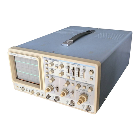
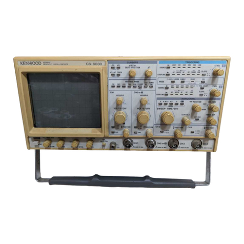
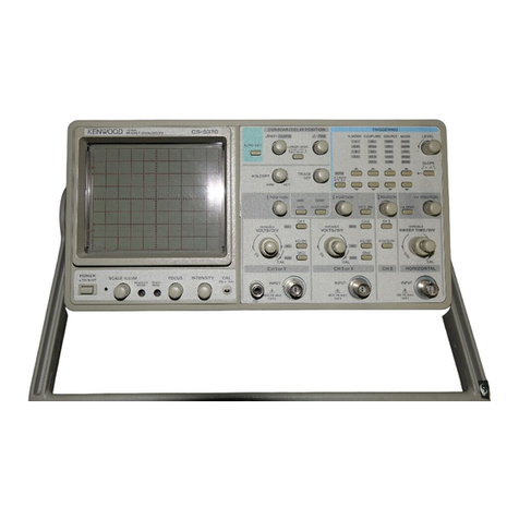
Kenwood CS-3025 User manual

20MHz
COMPACT
OSCILLOSCOPE
INSTRUCTION
MANUAL
KENWOODCORPORATION
©PRINTED
IN
JAPANB50-7683-00(T)
90/12111098765432189/12
11
1098765432
CS-3025
KENWOOD

SAFETY
Symbol
in
This
Manual
This
symbolindicateswhereapplicablecautionaryorotherimformationistobefound.
Power
Source
This
equipmentoperates
from
a powersourcethatdoesnotapplymorethan250V rms
betweenthesupplyconductorsorbetweeneithersupplyconductorandground.A pro-
tectivegroundconnectionbywayofthegroundingconductorinthepowercordis
essen-
tialfor
safe
operation.
GroundingtheProduct
This
equipmentisgrounded
through
thegroundingconductorofthepowercord.Toavoid
electrical
shock,plugthepowercord
into
a properlywiredreceptaclebeforeconnecting
totheequipment
input
or
output
terminals.
Use
theProperPowerCord
Use
onlythepowercordandconnectorspecifiedforyourproduct.
Use
theProper
Fuse
To
avoidfirehazard,usea fuseofthecorrecttype.
DonotOperateinExplosiveAtmospheres
To
avoidexplosion,donotoperatethisproductinanexplosiveatmosphere.
DonotRemoveCoveror
Pane!
To
avoidpersonalinjury,donotremovethecoverorpanel.
Refer
servicingtoqualified
personnel.
VoltageConversion
Ifthepowersourceisnotappliedtoyourproduct,contactyourdealer.Toavoidelectrical
shock,
donotperformthevoltageconversion.
2

CONTENTS
SAFETY
2
OVERVIEW
ANDCONFIGURATION4
SPECIFICATIONS
5
PREPARATION
FORUSE7
CONTROLSANDINDICATORS9
FRONTPANEL9
REAR
PANEL14
BOTTOM
PANEL15
OPERATION• 16
INSTALSTARTINGPROCEDURE16
[1]
NORMAL
SWEEP
DISPLAYOPERATION16
[2]
MAGNIFIED
SWEEP
OPERATION19
[3]X-YOPERATION19
[4]VIDEOSIGNALOBSERVATION19
APPLICATION20
PROBE
COMPENSATION20
TRACE
ROTATIONCOMPENSATION20
DCVOLTAGEMEASUREMENTS20
MEASUREMENTOFTHEVOLTAGE
BETWEEN
TWOPOINTSONA WAVEFORM22
ELIMINATION
OFUNDESIREDSIGNALCOMPONENTS23
TIMEMEASUREMENTS24
FREQUENCY
MEASUREMENTS24
APPLICATIONOFX-YOPERATION26
MAINTENANCE
ANDADJUSTMENT27
MAINTENANCE
27
ADJUSTMENT28
3

OVERVIEW
ANDCONFIGURATION
OVERVIEW
This
unit
isa compact,light-weight,highperformanceportableoscilloscopeequipped
with
rectangularCRT
with
internalgraticule.
The
frequencybandwidthof20MHzandselectablesweeptimeof0.2jis/divto1 s/div
forthevertical
axis
allowsusefora widerangeofapplications.Itisalsoequipped
with
such
featuresasmagnificationfunctionsfortheverticalandhorizontal
axes,
singlesweep
function,andTV
sync
function.
These
featuresmakeittheidealoscilloscopefortheservice
benchandvarioustypesofmaintenance.
CONFIGURATION
The
following
itemsarecontainedinthepacking
case.
Whenunpacking,makesurethat
all
itemshavebeenincluded.
Oscilloscope
1 pc.
Probe
(PC-30)
2 pes.
Panel
cover1 pc.
Instructionmanual1 pc.
Inaddition,the
following
arealsoavailableasoptional
accessories
(soldseparately).
Carrying
case
(soft)MC-81
Carrying
case
(hard)MC-82
4

SPECIFICATIONS
CRT
Type
RectangularhighluminanceCRT(withinternal
graticule)
Acceleration
VoltageApprox.1.8kV
Display
Area
8x10divflat-face(1div= 6.35mm)
VERTICAL
AXIS
OperatingModesCH1,CH2,ALT,
CHOP,
ADD
Sensitivity
5 mV/divto5 V/div,+/-3%
Sensitivity
Magnification...5times+1-5% (x5 MAGused)
Attenuator1-2-5stepsequence,10ranges,adjustablebetween
ranges
Frequency
Response
5
mV/divto5 V/divDC:DCto20MHz,-3dB
AC:
5 Hzto20MHz,-3dB
x5
MAGusedDC:DCto4 MHz,-3dB
AC:
5 Hzto4 MHz,-3dB
InputImpedance1 Mohm,approx.40pF
Rise
Time17.5nsor
less
(20MHz)
Crosstalk
-40dBminimum
Polarity
InversionCH2only
Chop
FrequencyApprox.50kHz
/\MaximumInputVoltage800Vp-por400V
(DC
+ ACpeak)
HORIZONTAL
AXIS
OperatingModesX-Yoperationselectable
with
sweepknob
X
axis
selectable
with
TRIG
orX
Y
axis
selectable
with
V orY MODE
Sensitivity
Same
asvertical
axis
InputImpedance
Same
asvertical
axis
Frequency
Response
DC:DCto200kHz,-3dB
AC:
5 Hzto200kHz,-3dB
X-Y
Phase
Difference3°or
less
at10kHz
/f\MaximumInputVoltage
Same
asvertical
axis
5

SWEEP
Sweep
TypeNORM:Triggeringsweep
AUTO:
Sweep
freerunsinabsenceof
trigger
Sweep
Time0.2^s/divto1 s/div+/-3%in21ranges,1-2-5se-
quence,
adjustablebetweenranges
Sweep
Magnification5 times+/-5%
A
TRIGGERING
Internal
Sync
INT,
LINE
External
Sync
EXT
External
Sync
Input
Impedance
1 Mohm,Approx.90pF
MaximumExternalTrigger
Voltage50V
(DC
+
ACpeak)
Sync
CouplingAC,DC,TV-V,TV-H
Polarity
+ /-
Trigger
Sensitivity
Coupling
Frequency
Amplitude(Voltage)
Coupling
Frequency
INT
EXT
DC
DC~2
MHz
-20MHz 0.5div
1
div 0.1Vp-p
0.2Vp-p
AC
10Hz~2MHz
-20MHz 0.5div
1
div 0.1Vp-p
0.2Vp-p
TV-H,
V
2
div 0.4Vp-p
CALIBRATION
VOLTAGE
Squarewave(positivepolarity)
1
Vp-p± 3%,1 kHz± 3%
POWER
REQUIREMENTS
Power
SupplyVoltageAC
100/120/220/240
V ±10%50/60Hz
Power
ConsumptionApprox.22W (at100V AC)
DIMENSIONSANDWEIGHT
Dimensions.
216(width)x 89(height)x 298(depth)mm
WeightApprox.4 kg
OPERATING
TEMPERATURE
AND
HUMIDITY
FOR
GUARANTEED
SPECIFICATIONS
5
to35°C,85%maximumRH
ACCESSORIES
Probe
(PC-30)
2 pes.
InstructionManual1 pc.
Panel
Cover1 pc.
6

PREPARATION
FORUSE
SAFETY
Before
connectingtheinstrumenttoa powersource,carefullyreadthe
following
infor-
mation,thenverifythattheproperpowercordisusedandtheproperlinefuseisinstalled
forpowersource.Thespecifiedvoltageisshownatthe
left
sideofthepowercordon
therearpanel.Ifthepowercordisnotappliedforspecifiedvoltage,thereis
always
a
certain
amountofdanger
from
electricshock.
Line
voltage
This
instrumentoperatesusingAC-power
input
voltagesthat100/120/220/240V atfre-
quencies
from
50Hzto60Hz.
Power
cord
The
groundwireofthe3-wireACpowerplug
places
the
chassis
andhousingofthe
oscil-
loscope
atearthground.Donotattempttodefeatthegroundwireconnectionorfloat
theoscilloscope;todosomayposea greatsafety
hazard.
The
appropriatepowercordissuppliedbyan
option
thatisspecifiedwhentheinstrument
is
ordered.
The
optionalpowercordsareshownasfollowsinFig.1.
Line
fuse
The
fuseholderislocatedontherearpanelandcontainstheline
fuse.
Verifythatthe
properfuseisinstalledbyreplacingtheline
fuse.
EQUIPMENT
PROTECTION
1.
Neverallowa smallspotofhighbrilliancetoremainstationaryonthe
screen
formore
thana few
seconds.
The
screen
maybecomepermanentlyburned.A spotwilloccur
onlywhenthescopeissetupforX-Yoperationandnosignalisapplied.Eitherreduce
theintensitysothespotisbarelyvisible,switchbacktonormalsweepoperationwhen
nosignalisapplied,orsetupthescopeforspotblanking.
2.
Nevercovertheventilatingholesonthetopoftheoscilloscope,asthiswill
increase
theoperatingtemperatureinsidethe
case.
3.
Neverapplymorethanthemaximumratingtotheoscilloscopeinputs.
^CH1,
CH2
INPUT
jacks:
800
Vp-por400V
(DC+AC
peak)
EXT
TRIG
INPUT
jack:
50
V
(DC
+ AC
peak)
Never
applyexternalvoltagetotheoscilloscope
output
terminals.
4.
Always
connecta cable
from
theearthground(GND)terminaloftheoscilloscopeto
the
chassis
oftheequipmentundertest.
Without
thiscaution,theentirecurrentfor
theequipmentundertestmaybedrawn
through
theprobeclip
leads
undercertaincir-
cumstances.
Such
conditionscould
also
posea safety
hazard,
whichthegroundcable
willprevent.
5.
Always
usetheprobegroundclipsforbestresults.Donotuseanexternalgroundwire
inlieuoftheprobegroundclips,asundesiredsignalsmaybeintroduced.
7

6.
OperationadjacenttoequipmentwhichproducesstrongACmagneticfieldsshouldbe
avoidedwherepossible.
This
includessuchdevicesaslargepowersupplies,transformers,electricmotors,etc.,
thatareoftenfoundinanindustrialenvironment.Strongmagneticshieldscanexceed
thepracticalCRTmagneticshieldinglimitsandresultinterferenceanddistortion.
7.
Probecompensationadjustmentmatchestheprobetotheinputofthescope.Forbest
results,
compensationofprobeshouldbeadjustedinitially,thenthesameprobeal-
ways
usedwiththeinputofscope.Probecompensationshouldbereadjustedwhenever
a
probefroma differentscopeis
used.
(Seepage20)
8.
InX-Yoperation,donotpulloutthe
PULL
x 5 MAGswitch.Ifpulledoutit,noisemay
appeare
onthewaveform.
Plug
configuration
Power
cord
and
plugtype
Factory
installed
instrumentfuse
Line
cordplugfuse
NorthAmerican
120volt/60Hz
Rated
15amp
(12ampmax;NEC)
0.5A,250V
Fast
blow
AGC/3AG
None
Universal
Europe
220volt/50Hz
Rated
16amp
0.3A,250V
Fast
blow
5
x 20mm None
U.K.
240volt/50Hz
Rated
13amp
0.3A,250V
Fast
blow
5x30mm
0.3A
Type
C
Australian
240volt/50Hz
Rated
10amp
0.3A,250V
Fast
blow
5x30mm None
NorthAmerican
240volt/60Hz
Rated
15amp
(12ampmax;NEC)
0.3A,250V
Fast
blow
AGC/3AG
None
Switzerland
240volt/50Hz
Rated
10amp
0.3A,250V
Fast
blow
AGC/3AG
5x30mm
None
Fig.
1 PowerinputVoltageConfiguration
8

CONTROLS
ANDINDICATORS
FRONT
PANEL
©POWER
Power
switchfortheoscilloscope.
Pressing
this
control
onceturnsthepoweronand
pressing
itagainturnsthepoweroff.
®Pilot Lamp
Lamp
lightswhentheoscilloscopeison.
(3)
CALTerminal
Voltageterminalforcalibrationofprobes.Providesanapproximately1 kHzsquarewave
at1 V
with
positivepolarity.
0$
POSITION/PULL
x 5 MAG
Rotationadjuststhevertical
position
ofchannel1 traceonthedisplay.Pullingthisknob
increases
thevertical
axis
sensitivity5 times.
®VOLTS/DIV
Sets
thevertical
axis
sensitivityusingtheverticalattenuatorforchannel1.
This
knob
can
beswitchedina 1-2-5sequence.Settingthe
VARIABLE
knob(6)totheCALposi-
tion
providescalibratedvertical
axis
sensitivity.
DuringX-Yoperation,this
control
serves
astheattenuatorfortheX
axis
orY
axis.
9
Fig.
2-1

Fig.
2-2
©
VARI
(ABLE)
Rotationprovidesfinecontrolofchannel1 verticalattenuation.Allowscontinuousad-
justmentbetween
VOLTS/DIV
ranges.
Inthefullyclockwise
(CAL)
position,theverti-
cal
attenuatoriscalibrated.DuringX-Yoperation,thiscontrol
serves
astheX
axis
or
Y
axis
attenuatorfineadjustment.
©
AC-GND-DC
This
lever
selects
thecouplingmethodusedfortheCH1vertical
axis
input
signal.
AC:
InputsignalisACcoupled,andDCcomponentisblocked.
GND:
Inputsignalandverticalamplifierareseparatedandinputtoverticalamplifier
is
grounded.
This
allowsforconfirmationofthegroundpotential.
DC:
InputsignalisDCcoupledallowingformeasurementincludingDCcomponent.
This
lever
servers
astheX
axis
orY
axis
inputselectorduringX-Yoperation.
®
CH1
INPUT
Vertical
axis
inputjackforchannel1.
Serves
astheX
axis
orY
axis
inputjackduring
X-Y
operation.
(D$ POSITION/PULLx 5 MAG
Performs
the
same
functionforchannel2 asthechannel1 *
POSITION
control.
Serves
as
theY positionadjustmentcontrolduringX-Yoperation.
10

©VOLTS/DIV
Vertical
axis
attenuatorforchannel2.Performsthesame
function
forchannel2 as
thechannel1
VOLTS/DIV
control.
Serves
astheX
axis
orY
axis
attenuationadjust-
ment
control
during
X-Yoperation.
©
VARI
(ABLE)
Rotationprovidesfine
control
ofchannel2 attenuation.Performsthesame
function
forchannel2 asthechannel1
VARIABLE
control.
Serves
astheX
axis
orY
axis
at-
tenuationfineadjustment
control
during
X-Yoperation.
©AC-GND-DC
This
leverselectsthecoupling
method
usedforthechannel2 vertical
axis
input
signal.
Performsthesame
function
asthechannel1
AC-GND-DC
control.
Serves
astheY
axis
orY
axis
input
selector
during
X-Yoperation.
©CH2INPUT
Vertical
axis
input
jackforchannel2.
Serves
astheX
axis
orY
axis
input
jack
during
X-Y
operation.
@VorY
MODE
This
switchselectsthevertical
axis
operationmodeand
serves
astheY
axis
selection
switch
during
X-Yoperation.
CH1:
Channel1
input
signalisdisplayedonthe
CRT.
Channel1 istheY
axis
ifthis
modeisselected
during
X-Yoperation.
CH2:
Channel2
input
signalisdisplayedonthe
CRT.
Channel2 istheY
axis
ifthis
modeisselected
during
X-Yoperation.
ALT:
Channel1 andchannel2 signalsaredisplayedalternatelyontheCRT
with
each
sweep.
CHOP:
Channel1 and2 signalsaredisplayedalternatelyontheCRTata
repetition
rateof50kHzormore.
ADD:Thealgebraicsumofthechannel1 and2 signalisdisplayedonthe
CRT.
If
CH2
INV© isengaged,thedifferenceisdisplayedontheCRT.
Note:
TheALT,CHOP,andADDmodescannotbeusedduringX-Yoperation.
©CH2INV
Invertsthe
polarity
ofthechannel2 signal.
©TRIGorX1 CHI/ _m. CH2
This
button
selectsthe
trigger
sourcewhenaninternal
trigger
(INT)isselected.
Serves
as
theX
axis
selectionswitch
during
X-Yoperation.
CH1:
Channel1
input
signal
serves
asthe
trigger
source.Channel1 becomesthe
X
axis
ifthis
button
ispressed
during
X-Yoperation.
CH2:
Channel2
input
signal
serves
asthe
trigger
source.Channel2 becomesthe
X
axis
ifthis
button
ispressed
during
X-Yoperation.
11

Fig.
2-3
©
INTENSITY
Adjuststhebrightnessofthetrace.
@
LEVEL/PULL
SLOPE
(-)
LEVEL:
Triggerleveladjustmentcontrol.Determines
point
on
trigger
signalwave-
form
wheresweepstarts.
SLOPE:
Trigger
polarity
selector.Pullingtheknobtriggersthesweepatthefalling
slopeofthe
input
waveform.
<§)AUTO/NORM(TRIGMODE)
Knobforselectingthe
triggering
mode.
AUTO:
Triggeredsweepoperationwhen
trigger
signalispresent,automatically
generatessweep(freerun)inabsenceof
trigger
signal.
NORM:Normal
triggered
sweepoperation.Unlike
AUTO,
nosweepappearswhen
theproper
trigger
signalisnotapplied.
©© NORM/LINE(TRIG
SOURCE)
Select
the
trigger
source
(sync
signalsource).The
following
trigger
sourcescanbe
selected.
WhenNORMisselected
with
theswitch
@>,
switch@ selectseitherinternal
triggering
(
_•_INT)orexternal
triggering
(EXT).
INT:Internal
triggering
isselectedandthesweepis
triggered
bythesignal
input
forthevertical
axis.
Eitherthechannel1 orchannel2 signalcanbeselect-
edasthe
trigger
sourceusing
TRIG
orX ©.
EXT:
The
trigger
sourceisthesignalappliedtotheEXT.
TRIG
jack@.
When
LINE
isselected
with
switch(§):
LINE:
Thesweepis
triggered
bythelinepowerfrequency.
12

®
(23)
TRIG
COUPLING
Select
thecouplingmethodusedforthetrigger
signal.
When
NORMisselectedwithswitch@,eitherACcoupling(
JI_
AC)orDCcoupling
(
_M_
DC)canbeselectedwithswitch(§).
AC:
TriggersignalisACcoupledtothe
sync
circuit.
Blocks
DCcomponentofinput
signal.
Mostcommonlyusedpositionforwaveformobservation.
DC:
TriggersignalisDCcoupledtothe
sync
circuit.
Sweep
istriggerbysignalin-
cludingDCcomponent.
When
TV(JL)
isselectedwithswitch
(22),
vertical
sync
(_•_)orhorizontal
sync
(J*.)
is
selectedbyswitch
(23).
V:
Sweep
istriggeredbyvertical
sync
pulses
ofvideo
signal.
H:
Sweep
istriggeredbyhorizontal
sync
pulses
ofvideo
signal.
®
SWEEP
VARIABLE
Provides
fineadjustmentofsweeptime;continuousadjustmentispossiblebetween
steps
selectedby
SWEEP
TIME/DIV
©.
Sweep
timeiscalibratedbyintheextremeclock-
wise
(CAL)position.
(25)
SWEEP
TIME/DIV
Sweep
time
coarse
selector.
Selects
sweeptimesbetween0.2/ts/divand1 s/divin
21
steps.
Indicated
values
arecalibratedwhen
SWEEP
VARIABLE
® controlissetto
CAL
position(fully
clockwise).
OscilloscopeissettoX-Yoperatingmodewhenthis
knobisrotatedtofullycounterclockwise(X-Y)position.InX-Yoperation,sweeping
stops
andthesourceselectedby
TRIG
orX © becomestheX
axis
amplifierandthe
source
selectedbyV orY
MODE
® becomestheY
axis
amplifier.
©
%
POSITION/PULL
x 5 MAG
Rotationadjuststhehorizontalpositionofthetraceonthedisplay.Pullingthisknob
increases
thesweeptimefivetimes.The
SWEEP
TIME/DIV
valueis
1
/5oftheindicat-
ed
valueatthistime.
13

Rear
Panel
Fig.
3
@
GNDTerminal
Chassis
groundterminalusedforestablishinga commongroundwithotherequipment.
<§)
EXT.
TRIG
Jack
Inputterminalforexternaltrigger
signal.
Whenthe
TRIG
SOURCE
@>
controlissetto
NORM
and© issetto
EXT,
thesignalinputtothisterminalbecomesthetrigger
signal.
(§)
Fuse
Holder
Contains
theline
fuse.
Verifythattheproperfuseisinstalledwhenreplacingtheline
fuse.
100
V to120V 0.5A
200
V to240V 0.3A
14

BOTTOM
PANEL
Fig.
4
(§)
TRACE
ROTATION
Electrically
rotatestracetohorizontalposition,
Adjustwhenstrongmagneticfields
cause
thetracetobetilted.
©
FOCUS
Adjusts
thetracefor
optimum
focus.
15

OPERATION
INITIALSTARTING
PROCEDURE
Untilyoufamiliarizeyourself
with
theuseofallcontrols,the
following
proceduremay
beusedtostandarizethe
initial
settingofcontrolsasa reference
point
andto
obtain
trace
ontheCRTinpreparationforwaveformobservation.
Whenusingtheprobe(s),refertoprobe'sinstructionsand
"PROBE
COMPENSATION"
listedin
APPLICATION
ofthismanual.
[1]NORMAL
SWEEP
DISPLAY
OPERATION
1.
Push
the
POWER
switch© — thepowersupply
will
beturnedonandthe
pilot
lamp
will
light.
Set
thesemodesasfollows;
V
orY MODE@:CH1
TRIG
MODE®:AUTO
2.
Thetrace
will
appearinthecenteroftheCRTdisplayandcanbeadjustedbytheCH1
^
POSITION
© and^ •
POSITION
© controls.Next,adjustthe
INTENSITY
@ and,
if
necessary,
the
FOCUS
(fj)for
ease
ofobservation.
3.
VerticalModes
Applyan
input
signaltotheCH1
INPUT
® jackandadjustthe
VOLTS/DIV
©
control
fora suitable
size
displayofthewaveform.Ifthewaveformdoesnotappearinthe
display,adjustthe
VOLTS/DIV
andy
POSITION
controlsto
bring
thewaveform
into
thecenter
portion
oftheCRTdisplay.Operation
with
a signalappliedtotheCH2IN-
PUT
(J3)
jackandtheV orY MODEsettoCH2issimilartotheaboveprocedure.
IntheADDmode,thealgebraicsumofCH1+ CH2isdisplayed.IftheCH2INV© switch
has
beenengaged,thealgebraicdifferenceofthetwowaveforms,CH1— CH2isdis-
played.
If
both
channelsaresettothesame
VOLTS/DIV,
thesumordifferencecan
bereaddirectlyin
VOLTS/DIV
from
the
CRT.
IntheALTmode,onesweepdisplayes
thechannel1 signalandthenextsweepdisplaysthechannel2 signalinanalternating
sequence.
16
Fig.
5

Inthe
CHOP
mode,thesweepischoppedatanapproximate50kHzrateandswitched
betweenCH1andCH2.
Note
that
inthe
CHOP
modeofoperation,the
trigger
source
becomesthechoppingsignalitself,makingwaveformobservationimpossible.UseALT
modeinsteadinsuch
cases,
orselecta
trigger
SOURCE
ofCH1orCH2.
Ifnotraceisobtainable,refertothe
following
TRIGGERING
procedures.
4.
Aftersettingthe
SOURCE
switch,adjustthe
SLOPE
control.
The
displayonthescreen
will
probablybeunsynchronized.Referto
TRIGGERING
proce-
durebelowforadjustingsynchronizationandsweepspeedto
obtain
a stabledisplay
showingthedesirednumberofwaveform.
TRIGGERING
The
input
signalmustbeproperly
triggered
forstablewaveformobservation.
TRIGGER-
ING
ispossiblethe
input
signalINTernallytocreatea
trigger
or
with
an
EXTernally
provid-
edsignalof
timing
relationshiptotheobservedsignal,appliyingsucha signaltotheEXT
TRIG
INPUTjack.
The
SOURCE
switchselectsthe
input
signal
that
istobeusedto
trigger
thesweep,
with
INT
syncpossibilities(CH1,CH2,
LINE)
andEXTsyncpossibility.
*Internal
Sync
Whenthe
SOURCE
selectionisinNORMandINT(CH1orCH2),the
input
signaliscon-
nectedtotheinternal
trigger
circuit.Inthisposition,a partofthe
input
signalfedtothe
INPUT
® or© jackisapplied
from
theverticalamplifiertothe
trigger
circuittocause
the
trigger
signal
triggered
with
the
input
signaltodrivethesweep.
WhentheV orY MODEselectionisinALT,theALT
position
isveryconvenientformeas-
uringthe
time
duration
ofthewaveform.However,forphaseor
timing
comparisonsbe-
tweenthechannel1 andchannel2 waveforms,
both
tracesmustbe
triggered
bythesame
sync
signal.
Whenthe
SOURCE
selectionisinNORMandINT
(CH1),
the
input
signalatthechannel
1
INPUT(8)jackbecomes
trigger
regardlessofthe
position
ofV orY MODE.Whenthe
SOURCE
selectionisinNORMandINT
(CH2),
the
input
signalatthechannel2 INPUT
©jackbecomes
trigger
regardlessofthe
position
ofV orY MODE.Whenthe
SOURCE
selectionin
LINE,
theAClinevoltagepoweringtheoscilloscopeisusedassynctriggering.
*External
Sync
Whenthe
SOURCE
selectionisinNORMand
EXT,
the
input
signalatthe
EXT
TRIG
INPUT
©jackbecomesthe
trigger.
Thissignalmusthavea
time
orfrequencyrelationshipto
thesignalbeingobservedtosynchronizethedisplay.Externalsyncispreferedforwave-
form
observationinmanyapplications.Forexample,Fig.6 shows
that
thesweepcircuit
is
drivenbythegatesignalwhenthegatesignalintheburstsignalisappliedtotheEXT
TRIG
INPUTjack.Fig.6 alsoshowsthe
input/output
signals,wheretheburstsignalgener-
ated
from
thesignalisappliedtotheinstrumentundertest.
Thus,
accurate
triggering
can
beachieved
without
regardtothe
input
signalfedtotheINPUT(8)or@ jackso
that
no
further
triggering
isrequiredevenwhenthe
input
signalisvaried.
17

Trigger
signal
(Gate
signal)
•
CH1(Inputsignalto
amplifier,etc.)
CH2
(Outputsignal
fromamplifier,etc.)
*
Triggering
Level
Trigger
pointonwaveformisadjustedbythe
LEVEL/PULLSLOPE
® control.Fig.7 shows
therelationshipbetweenthe
SLOPE
and
LEVEL
ofthetriggerpoint.Triggeringlevelcan
be
adjustedas
necessary.
SLOPE
"-"
RANCE
LEVEL
*
AutoTrigger
When
the
TRIG
MODE(jj)selectionisin
AUTO,
thesweepcircuitbecomesfree-running
as
longasthereisnotrigger
signal,
permittinga checkofGND
level.
Whena trigger
sig-
nal
ispresent,thetriggerpointcanbedeterminedbythe
LEVEL
controlforobservation
as
inthenormaltrigger
signal.
Whenthetriggerlevel
exceeds
the
limit,
thetriggercircuit
also
becomesfree-runningwherethewaveformstartsrunning.Whenthe
LEVEL
control
is
pushedinand/or,whenthetriggersignalisabsentorthetriggeringlevel
exceeds
the
limit,
thereisno
sweep.
18
Fig.
6
SLOPE
" + "
RANGE
Fig.
7

[2]MAGNIFIED
SWEEP
OPERATION
Sfnce
merelyshorteningthesweeptimetomagnifya
portion
ofanobservedwaveform
can
resultinthedesired
portion
disappearingoffthe
screen,
suchmagnifieddisplayshould
beperformedusingthe
MAGNIFIED
SWEEP.
Using
the
POSITION
control,adjustthedesired
portion
ofwaveformtothe
CRT.
Pull
outthe
PULL
x 5 MAGcontroltomagnifythedisplay5 times.Forthistypeofdisplaythe
sweep
timeisthe
SWEEP
TIME/DIV
settingdividedby5.
[3]X-YOPERATION
For
somemeasurements,anexternalhorizontaldeflectionsignalisrequired.
This
isalso
referredtoasanX-Ymeasurement,wheretheY
input
providesverticaldeflectionand
X
input
provideshorizontaldeflection.
X-Y
operationpermitstheoscilloscopetoperformmanytypesofmeasurementsnotpos-
sible
with
conventionalsweepoperation.TheCRTdisplaybecomesanelectronicgraph
oftwoinstantaneousvoltages.Thedisplaymaybea directcamparisonoftwovoltages
such
asduringphasemeasurement,frequencymeasurement
with
Lissajous
waveforms.
To
useanexternalhorizontal
input,
usethe
following
procedure;
1.
Setthe
SWEEP
TIME/DIV
controltotheX-Yposition.
2.
Usethechannel1 probeforthevertical
input
andthechannel2 probeforthehorizon-
tal
input.
3.
Adjusttheamountofhorizontaldeflection
with
theCH2
VOLTS/DIV
and
VARIABLE
controls.
4.
TheCH2(vertical)
POSITION
(§)controlnow
serves
asthehorizontalpositioncontrol,
andthe^
POSITION
controlisdisabled.
5.
All
sync
controlsaredisconnectedandhavenoeffect.
[4]VIDEOSIGNALOBSERVATION
The
TV-V/H
switchpermitsselectionofverticalorhorizontal
sync
pulseforsweeptrig-
geringwhenviewingcompositevideowaveforms.IntheTV-Hposition,horizontal
sync
pulses
areselectedastriggerstopermitviewingofhorizontallineofvideo.
This
isalso
thepositionusedforviewingallnon-videowaveforms.IntheTV-Vposition,vertical
sync
pulses
areselectedastriggerstopermitviewingofverticalfieldsandframesofvideo.
Whenobservingthevideowaveforms,stabledisplayisobtainedonthescreenregardless
the
TRIGLEVEL
@ control.
Atmostpointsofmeasurement,a compositevideosignalisofthepolarity,thatis,the
sync
pulsesarenegativeandthevideoispositive.Inthis
case,
use"-"
SLOPE.
Ifthewaveformistakenata circuit
point
wherethevideowaveformisinverted,the
sync
pulses
arepositiveandthevideoisnegative.Inthis
case,
use" + "
SLOPE.
19

APPLICATION
PROBE
COMPENSATION
To
obtain
anaccuratemeasurementresult,theprobemustbeadjustedcorrectlybefore
measurement.
1.
ConnecttheprobetotheINPUTterminalandsetthe
control
fora normalsweepdisplay.
2.
ConnecttheprobetotheCALterminalonthe
front
panel,andadjustthe
SWEEP
TIME/DIV
control
todisplaya fewcyclesofthesignal
output
from
it.
3.
Adjustthetrimmerontheprobeto
obtain
the
following
correctcompensationwaveform.
Correct
compensation
Over
compensation
Insufficient
compensation
Fig.
8
TRACE
ROTATIONCOMPENSATION
Rotation
from
a horizontaltrace
position
canbethecauseofmeasurementerrors.
Adjustthecontrolsfora singledisplay.Setthe
AC-GND-DC
switchtoGNDand
TRIG
MODE
to
AUTO.
Adjustthey
POSITION
control
such
that
thetraceisoverthecenterhorizon-
talgraticuleline.Ifthetraceappearstobe
rotated
from
horizontal,alignit
with
thecenter
graticulelineusingthe
TRACE
ROTATION
control
locatedonthe
front
panel.
DC
VOLTAGE
MEASUREMENTS
This
proceduredescribesthemeasurementprocedureforDCwaveforms.
Procedure:
1.
Connectthesignaltobemeasuredtothe
INPUT
jack.SettheV orY MODEtothechannel
tobeused.Setthe
VOLTS/DIV
and
SWEEP
TIME/DIVswitchto
obtain
a normaldis-
playofthewaveformtobemeasured.Setthe
VARIABLE
control
totheCALposition.
20
Table of contents
Other Kenwood Test Equipment manuals

Kenwood
Kenwood CO-1506 User manual

Kenwood
Kenwood CS-1100 User manual

Kenwood
Kenwood DCS-8200 User manual

Kenwood
Kenwood CS-1022 User manual

Kenwood
Kenwood TH-77A User manual

Kenwood
Kenwood CS-5130 User manual

Kenwood
Kenwood CS-5170 User manual

Kenwood
Kenwood AG-203 User manual

Kenwood
Kenwood CV-1240 User manual

Kenwood
Kenwood CS-6020 User manual

Kenwood
Kenwood CS-5350 User manual

Kenwood
Kenwood CS-1065 User manual

Kenwood
Kenwood CAX-AD100 User manual

Kenwood
Kenwood CS-3035 User manual

Kenwood
Kenwood CS-5135 User manual

Kenwood
Kenwood CS-5200 Series User manual

Kenwood
Kenwood CS-5165 User manual

Kenwood
Kenwood CS-1352 User manual

Kenwood
Kenwood CS-5140 User manual

Kenwood
Kenwood CS-5130 User manual