Axiom NT25-P18 Manual

3603 Burron Avenue, Saskatoon, SK S7P 0E4 Ph: (306) 651-1815
email: sales@axiomind.com website: www.axiomind.com
NT25-P18 CONDENSATE NEUTRALIZATION TANK WITH PUMP
INSTALLATION, OPERATION, AND MAINTENANCE INSTRUCTIONS
NOTE - Check with your local water authority for regulations regarding discharge of treated
condensate to the drain or sewer system.
WARNING
1. Do not use to pump flammable or explosive fluids such as gasoline, fuel oil, alcohol, etc.
2. Do not use in explosive atmospheres.
3. Do not handle pump with wet hands, when standing on a damp surface, or in water.
4. To reduce the risk of electrical shock connect pump to a properly grounded grounding type
receptacle. It is reccommended to use the pump with a GFCI (ground fault circuit interrupter).
5. Connect the pump only to the power supply specified on the nameplate of the pump.
6. In any installations where property damage and/or personal injury might result from an
inoperative pump, a backup system and/or alarm should be used.
7. Do not twist or kink the drain hose.
8. Before doing any maintenance or repairs on the pump, disconnect the pump from the power
supply to avoid electrical shock.
9. Keep children away from pump.
10. This is a non-submersible pump.
11. Every installation or after-sales service should be done by a qualified service technician.
12. If the pump runs for more than 5 minutes before shutting off check the trouble shooting
chart on page 7 for a solution.
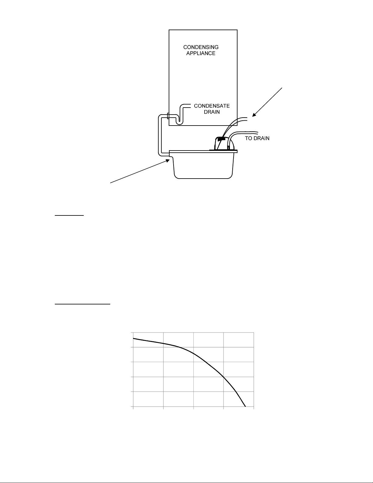
13. “Risk of damage to appliance”. The neutralization tank inlet must be at a lower elevation
than the condensate drain from appliance.
14. Do not allow exhaust flue gases to vent through the neutralization tank. All condensate
drains leading into the neutralizer must have a trap to prevent flue gas leakage. Flue gas leakage
can cause injury or death from carbon monoxide.
15. Connection to the appliance and neutralization tank must be installed to ensure that no
condensate backflow into the appliance can occur.
1

Installation Instructions
(1) Select a mounting location near the appliance. The pump must be mounted level and
horizontally. Run flexible corrosion resistant tubing or pipe from condensing appliance drain
into the inlet of the NT25-P18. Be sure the inlet piping is sloped downward to allow gravity
flow.
(2) Connect the provided 3/8” I.D. outlet tubing with the check valve. Extend outlet tubing from
the NT25-P18 straight up as high as necessary, but not higher than the maximum head/flow rate
(see pump performance on page 5) of the pump. Be sure that the outlet piping is not twisted or
clogged.
(3) Do not route the condensate line through any area that is exposed to freezing temperatures. If
traffic poses a risk, install some protection to prevent movement and/or damage.
(4) Check that the power source voltage matches with the pump’s requirement. Connect the
pump’s power cord to a constant source of power (not a fan or other device that runs
intermittently). Do not connect or link the appliance’s power cable directly to the pump’s power
cable. Use each of their power plugs respectively. If the pump’s power cable should be
extended, use a cable of same specification. All wiring should be done by qualified service
technician.
(5) Ensure that the condensate will flow freely from the appliance condensate drain into the NT25-P18,
and that the pump will remove the condensate to the drain.
2

3603 Burron Avenue, Saskatoon, SK S7P 0E4 Ph: (306) 651-1815
email: sales@axiomind.com website: www.axiomind.com
Permanently Removing the Check Valve
In the event that you find it necessary to remove the check valve permanently (outlet discharge
tubing passes through an area where freezing may occur), use a 7/32” drill bit on the inlet side of
the check valve to remove the ball and spring. Only insert drill bit half way through check valve.
See figure 1 below.
Figure 1: To remove ball and spring from bottom of check valve use 7/32” drill bit
NOTE - See maintenance section for check valve removal from pump (page 6, item 2).
7/32” drill bit
Inlet
outlet
3

Installation Instructions for the RIA10-1-SAA Control Panel for use with NT25-P18
The high level float switch can be wired to be N.C. or N.O. in the NT25-P18. It is factory wired
to be OPEN (N.C.) on HIGH LEVEL. See figure 2 and 3 below. Disconnect the power before
starting. The electrical ratings for the high level switch on the NT25-P18 are
125 or 250VAC
6A, 125V DC 0.4A, 250V DC 0.3A
1. Extend the two white wires from the high level float switch and push the cable through the
strain relief fitting on control panel and connect wires to terminals 1 and 2 on terminal strip.
Tighten strain relief nut to secure cable into panel. See figure 4 below.
2. Connect DCS wiring to remote alarm dry contacts as requested to provide alarm signal.
3. To disable the audible alarm, remove the jumper on the control board.
Figure 4: High level float connection from NT25-P18 to RIA10-1-SAA alarm panel
4. Plug the NT25-P18 into the RIA10-1-SAA panel.
OPTIONAL: If your condensing appliance has an auxiliary interlock for normally closed
contacts, you may connect the two white lead wires from the NT25-P18 to the interlock
terminals on your appliance. The contacts will open if the water level rises too high in the
NT25-P18 which will prevent an overflow if the pump is not working.
1
2
3
4
5
NC
NO
COM
FLOAT
SWITCH
TO DISABLE AUDIBLE ALARM REMOVE JUMPER
NOTE: LOW VOLTAGE WIRE INSULATION MUST BE
APPROVED FOR 300V
Fig. 2: High level float contacts in N.C. position Fig. 3: High level float contacts in N.O. position

3603 Burron Avenue, Saskatoon, SK S7P 0E4 Ph: (306) 651-1815
email: sales@axiomind.com website: www.axiomind.com
5
Figure 5:Installation diagram of the NT25-P18
Operation
Plug the NT25-P18 into the wall outlet. To test the safety switch unplug the pump, and pour water
into the NT25-P18 tank until the safety switch contacts open. Plug the pump in and the pump
should turn on. Ensure there are no leaks or kinks in the piping.
During operation the appliance condensate will flow through the neutralizing media, raising the
pH of the condensate to a level that will help prevent corrosion of the domestic drain and the
public sewer system. The pump will then remove the condensate to desired location (i.e. drain).
See figure 5 above.
Pump Performance
CONNECT TO CONDENSING
APPLIANCE AUXILIARY
INTERLOCK
INLET
0
5
10
15
20
25
0 20 40 60 80
Head (ft.)
Flow Rate (GPM)
NT25-P18 Pump Curve

6
Maintenance
1. Before attempting to service or disassemble any component, make sure that the unit is
disconnected from the power source.
2. Remove the drain hose from the inlet hole. Uninstall the check valve from the main plate (see
figure 6 below). Disassemble the outlet piping from the check valve. Clean the check valve and
be sure that the ball inside of check valve moves freely.
3. Remove the steel plate and plastic cover from the tank.
4. Be sure the floats move freely. Clean as necessary.
5. Remove neutralization media and clean the reservoir with warm water and mild soap. Rinse
with water. Replace LipHter+media in tank.
6. Check the inlet and outlet piping. Clean as necessary. Be sure there are no kinks in the line
that would inhibit flow.
7. After servicing, assemble the unit in the reverse order.
8. In case of a long-term break, remove water from the outlet piping and reservoir.
9. Monitor the cleanliness, level of the neutralization media, and pH level in the tank monthly. Remove
any precipitate coating or debris found to prevent blockages. The pH can be checked after the
condensate has exited the tank or by removing the lid and taking a sample from the pump out chamber.
Use a suitable pH test strip paper or an electronic pH meter for precise measurement. The neutralizing
media should be replaced when the pH level drops below the minimum level of the local water
authority, or after one year, whichever comes first. For replacement LipHter+ media contact your local
Axiom distributor or visit www.axiomind.com for more information.
To remove →Turn the check valve 90˚ counter-clockwise and lift
the check valve out of the hole
For Installation →Put the check valve into the hole and turn 90˚
clockwise
Figure 6

3603 Burron Avenue, Saskatoon, SK S7P 0E4 Ph: (306) 651-1815
email: sales@axiomind.com website: www.axiomind.com
ATTENTION: ADDITIONAL MAINTENANCE FOR BOILERS WITH ALUMINUM HEAT
EXCHANGERS
-Boilers with Aluminum heat exchangers deposite white salt on the neutralization media that
restricts flow through the neutralizer. To clean the media, remove the pump and cover,
thoroughly rinse the media with water, washing the salt out of the tank. Replace the pump
and cover.
Troubleshooting Chart
Problem Resolution
The unit does not run. a) Check the power supply.
b) Check the appliance to see if the condensate is actually being
produced.
c) Make sure the inlet piping is not clogged. If it is clogged, the
appliance may eventually be damaged.
The unit makes loud noises
when running.
a) Make sure the inside of reservoir is clean.
b) Make sure there is no siphoning action.
The unit runs but does not
pump the liquid out.
a) Check that the highest point of the outlet piping does not
exceed the maximum delivery head of the pump.
b) Make sure the outlet piping is not clogged.
c) Inspect the check valve following the maintenance
instructions.
Liquid drains back into the
pump from the outlet piping.
a) The check valve may have debris in it. Clean the check valve
following the maintenance instructions.
Liquid leaks from around the
check valve.
a) Make sure the outlet piping is tightly connected with the
check valve.
b) Make sure the check valve is fastened properly.
c) If the O-ring under the check valve is damaged, replace with
a new one.
Limited Warranty
The NT25-P18 is warranted against defects in materials and workmanship for one year.
7
F
igure 7
:
Salt precipitate deposited on
neutralization media from Aluminum heat
exchangers
F
igure 8
:
Neutralization media that has
been rinsed with clean water
Table of contents