DEUTSCH
INSTALLATION
Technische Daten
SK 1 | 3
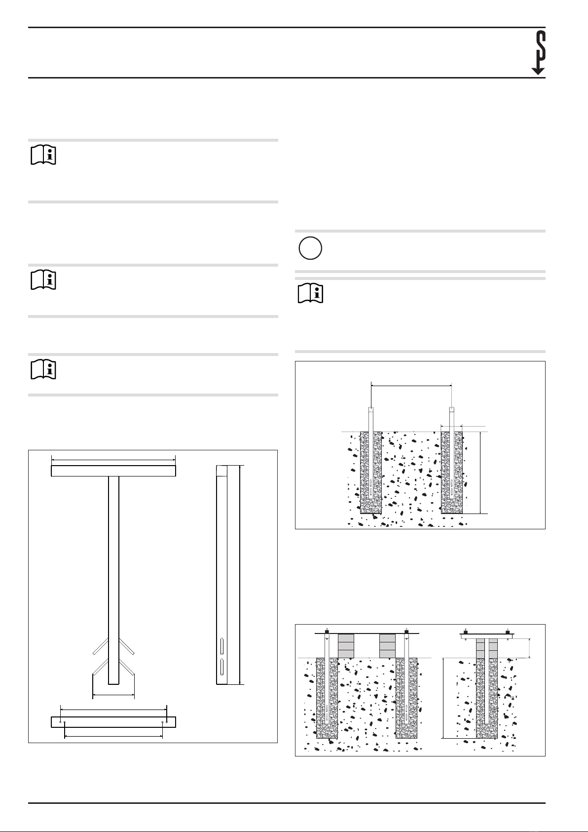
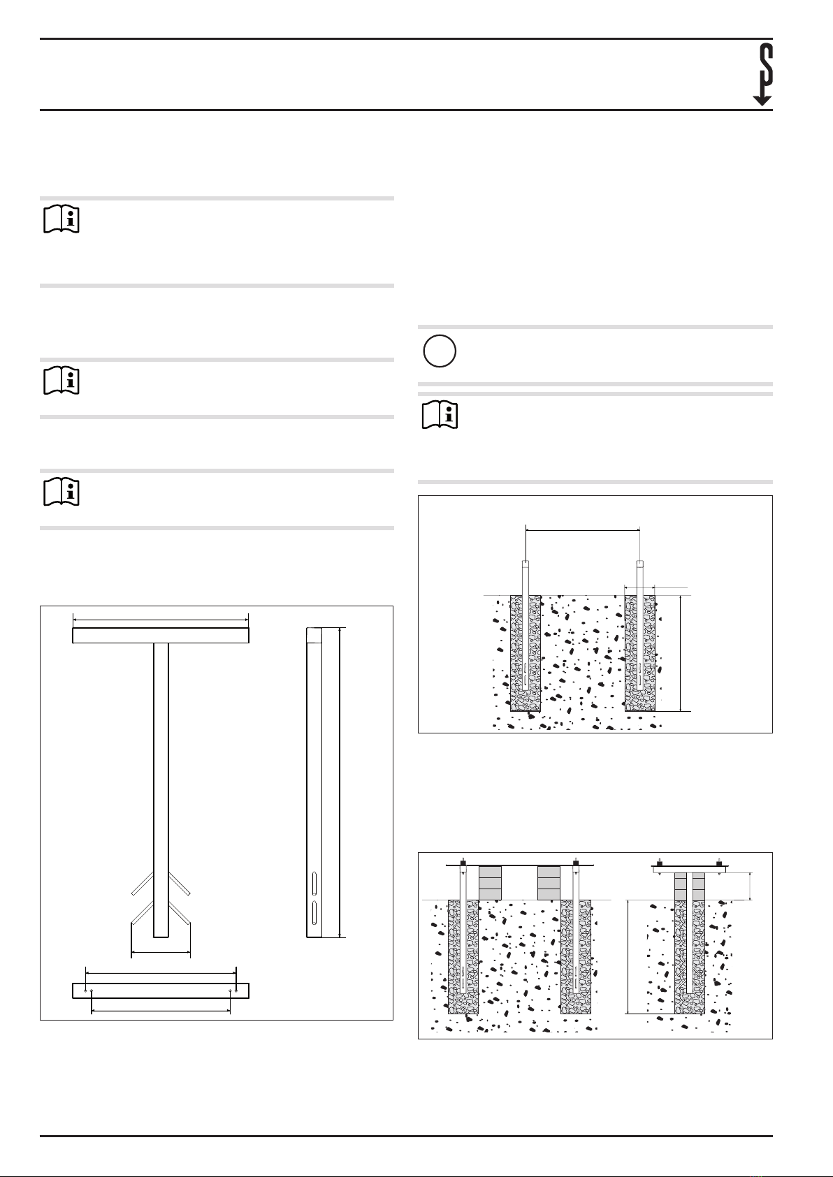
Setzen Sie die Konsolenträger in die Fundamentlöcher
ein.
Stellen Sie sicher, dass die Konsolenträger in der geforder-
ten Höhe aus dem Boden herausragen. Beachten Sie das
Abstandsmaß Konsolenträger / Boden.
Setzen Sie hierzu geeignete Abstandshalter, zum Beispiel
Ziegelsteine, unter die Konsolenträger.
1
2
82_03_14_0002_
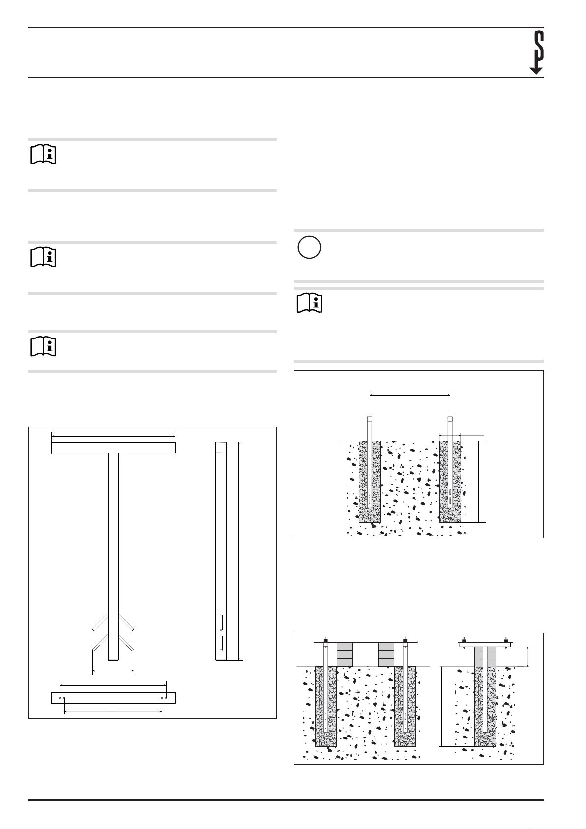
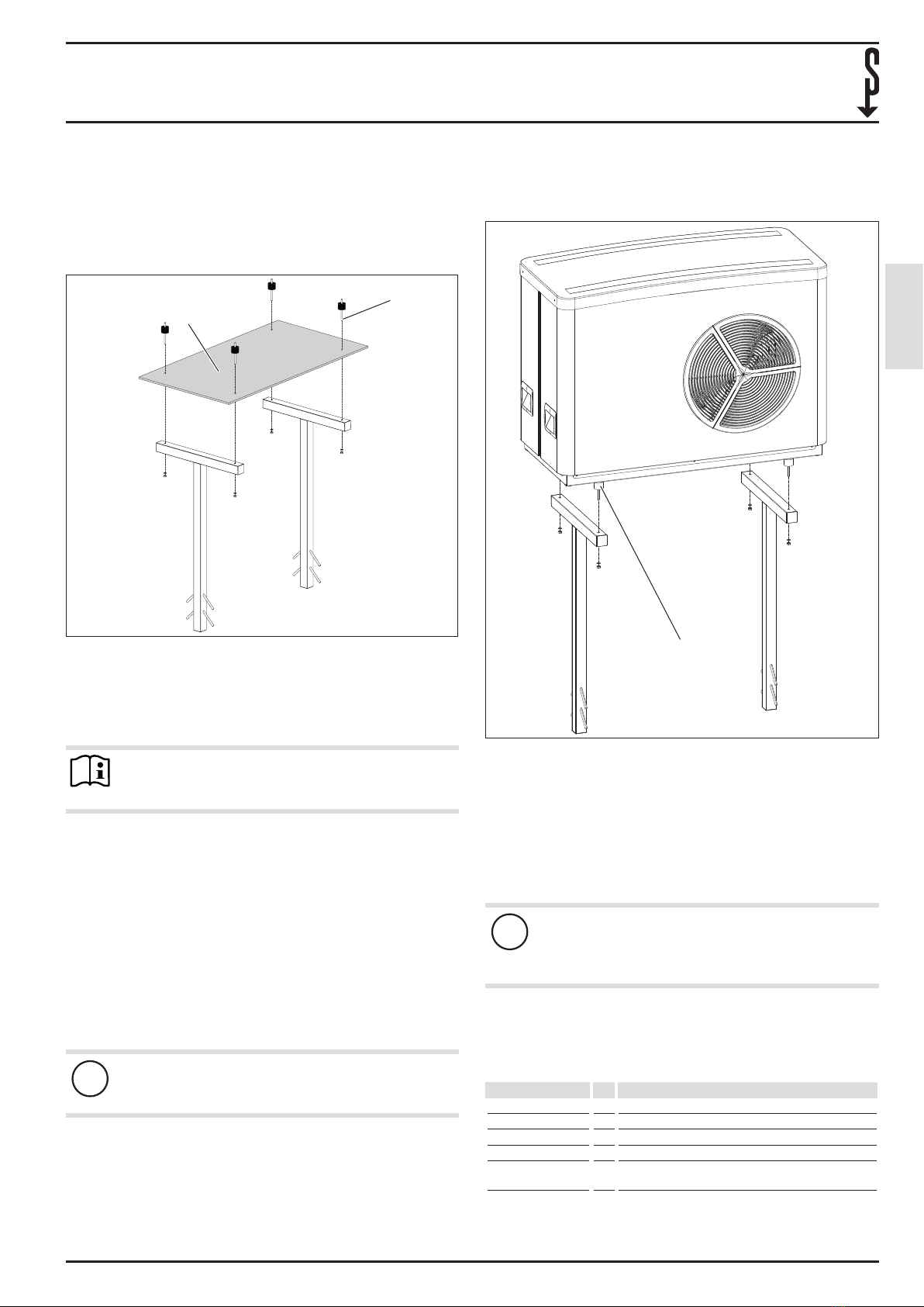
1 Montageschablone
2 Schwingungsdämpfer mit eingeschraubter
Gewindestange
Schrauben Sie die Gewindestangen bis zum Anschlag in
die Schwingungsdämpfer hinein.
Legen Sie die Montageschablone auf die Konsolenträger.
Hinweis
Durch Aufsetzen der Montageschablone wird die Kon-
sole in der richtigen Position gehalten.
Führen Sie die Schwingungsdämpfer mit den Gewin-
destangen durch die Montageschablone in die Konsolen-
träger ein.
Kontern Sie die Gewindestangen an der Unterseite der
Konsolenträger mithilfe der Muttern. Ziehen Sie die Mut-
tern mit der Hand fest.
Prüfen Sie die richtige Ausrichtung der Standkonsole mit-
hilfe einer Wasserwaage.
Richten Sie die Standkonsole bei Bedarf durch Verschie-
ben der Abstandshalter aus.
Wählen Sie einen geeigneten Betontyp aus, stellen Sie sicher,
dass er für Edelstahl geeignet ist.
Füllen Sie Beton in die Fundamentlöcher ein und verdich-
ten Sie diesen.
!Sachschaden
Lassen Sie den Beton aushärten. Beachten Sie die Hin-
weise des Betonherstellers.
Entfernen Sie die Schwingungsdämpfer, die Montage-
schablone und die Abstandshalter.
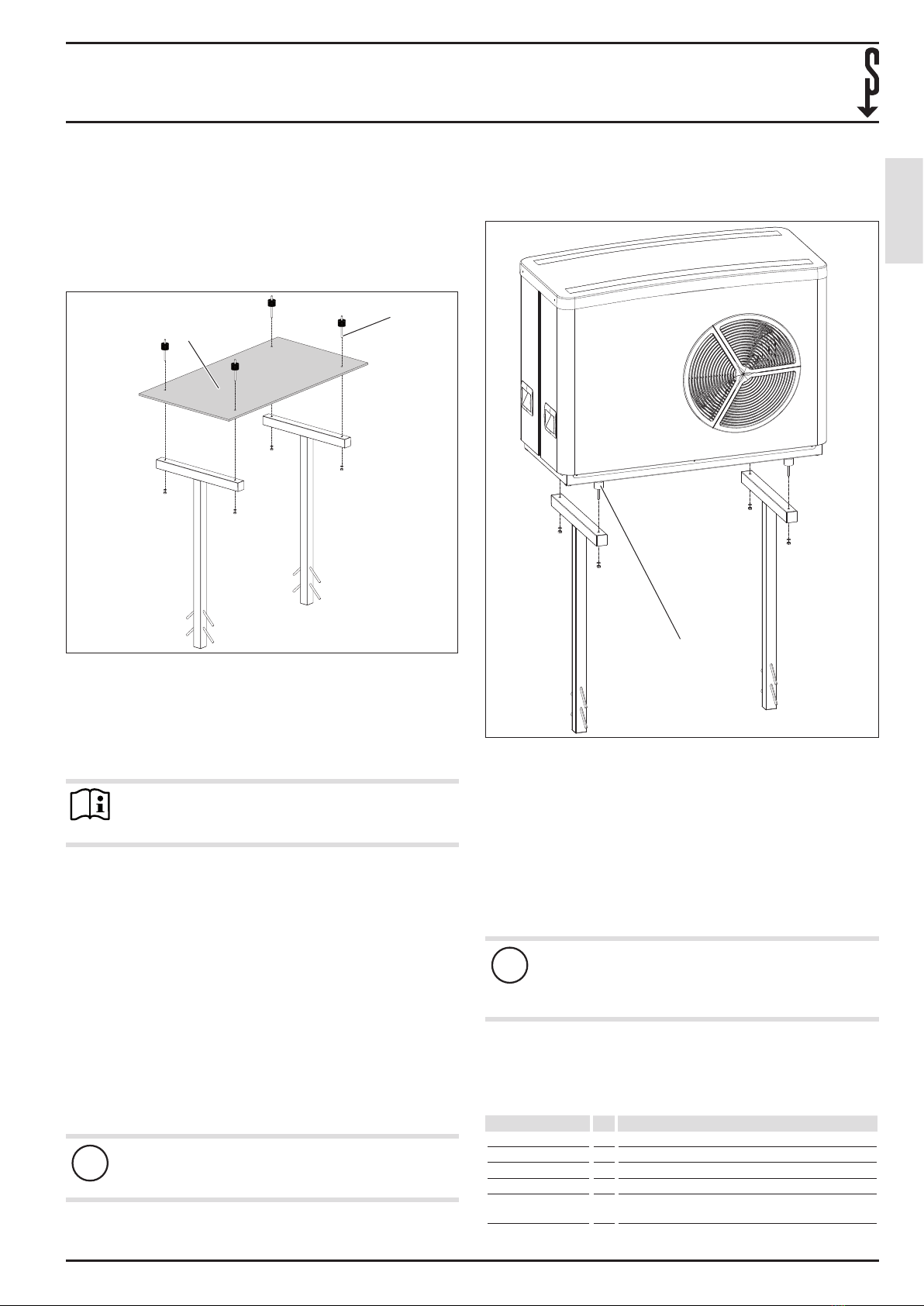
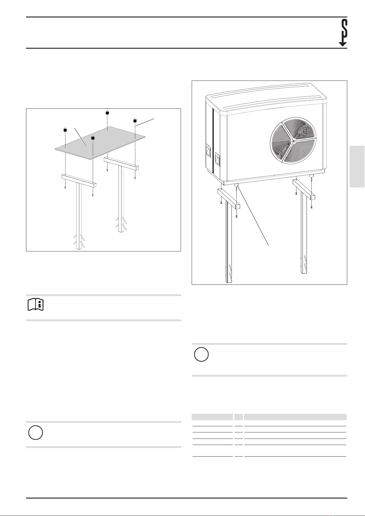
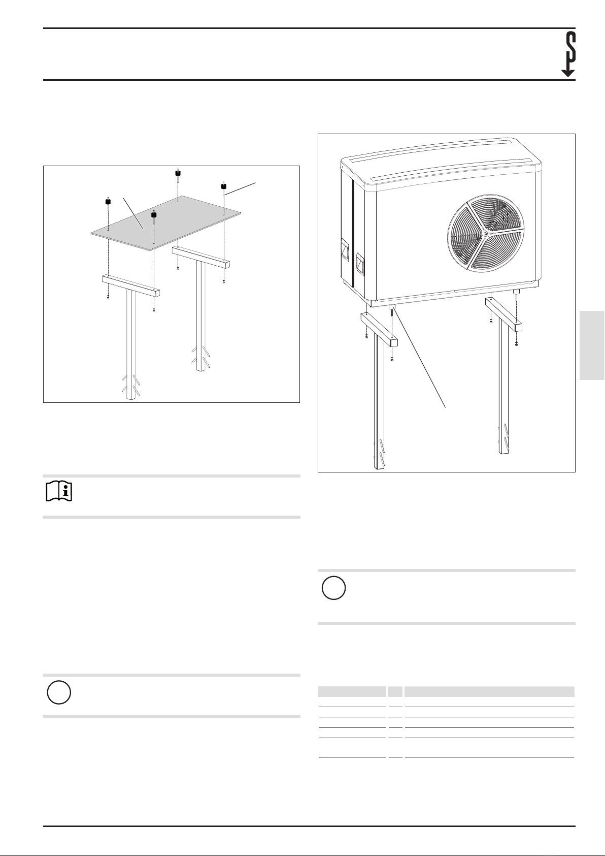
4.2 Wärmepumpe
Schrauben Sie die Gerätefüße vom Außengerät ab und
entsorgen Sie die Gerätefüße.
1
26_03_14_0115_
1 Eingeschraubter Schwingungsdämpfer mit
Gewindestange
Schrauben Sie die Schwingungsdämpfer mit dem Gewin-
deansatz in der dargestellten Position in das Außengerät
hinein (Innensitz der Gerätefüße).
Setzen Sie das Außengerät auf die Standkonsole, führen
Sie dazu die Gewindestangen der Schwingungsdämpfer
in die Konsolenträger ein.
Schrauben Sie die Gewindestangen mit den beigelegten
Unterlegscheiben und Muttern fest.
!Sachschaden
Lassen Sie die Installation von einem Fachhandwerker
prüfen, um sicherzustellen, dass eine dauerhafte und
sichere Aufstellung des Gerätes gewährleistet ist.
5. Technische Daten
5.1 Datentabelle
SK 1
232964
Höhe mm 950
Tiefe mm 570
Gewichtsbelastung kg 175
Geeignet für 10 AC(S), 15/25 I(S)-2, 15/25 IK(S)-2 und 15/20/25
AC(S)