Immergas UE AUDAX PRO V2 Product manual

UE AUDAX PRO V2
Outdoor Condensing Unit
Single-phase:
- UE AUDAX PRO 12 V2
- UE AUDAX PRO 14 V2
- UE AUDAX PRO 16 V2
ree-phase:
- UE AUDAX PRO 12 V2 T
- UE AUDAX PRO 14 V2 T
- UE AUDAX PRO 16 V2 T
IE
Instructions and warnings
Installer and Maintenance
technician
*1.045674ENG*
*1.045674ENG*

2
INDEX
Dear Customer,................................................................................. 3
General warnings ............................................................................. 4
Safety symbols used.......................................................................... 6
Personal protective equipment....................................................... 6
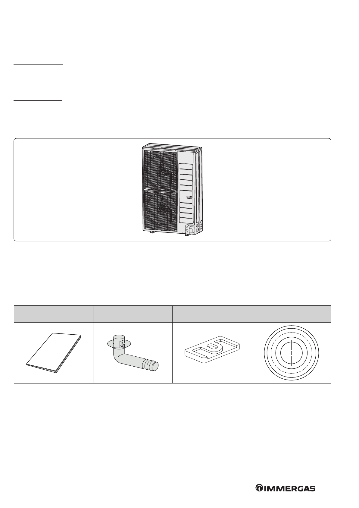
1 Product specications. ........................................................ 7
1.1 Product range....................................................................... 7
1.2 Accessories............................................................................ 7
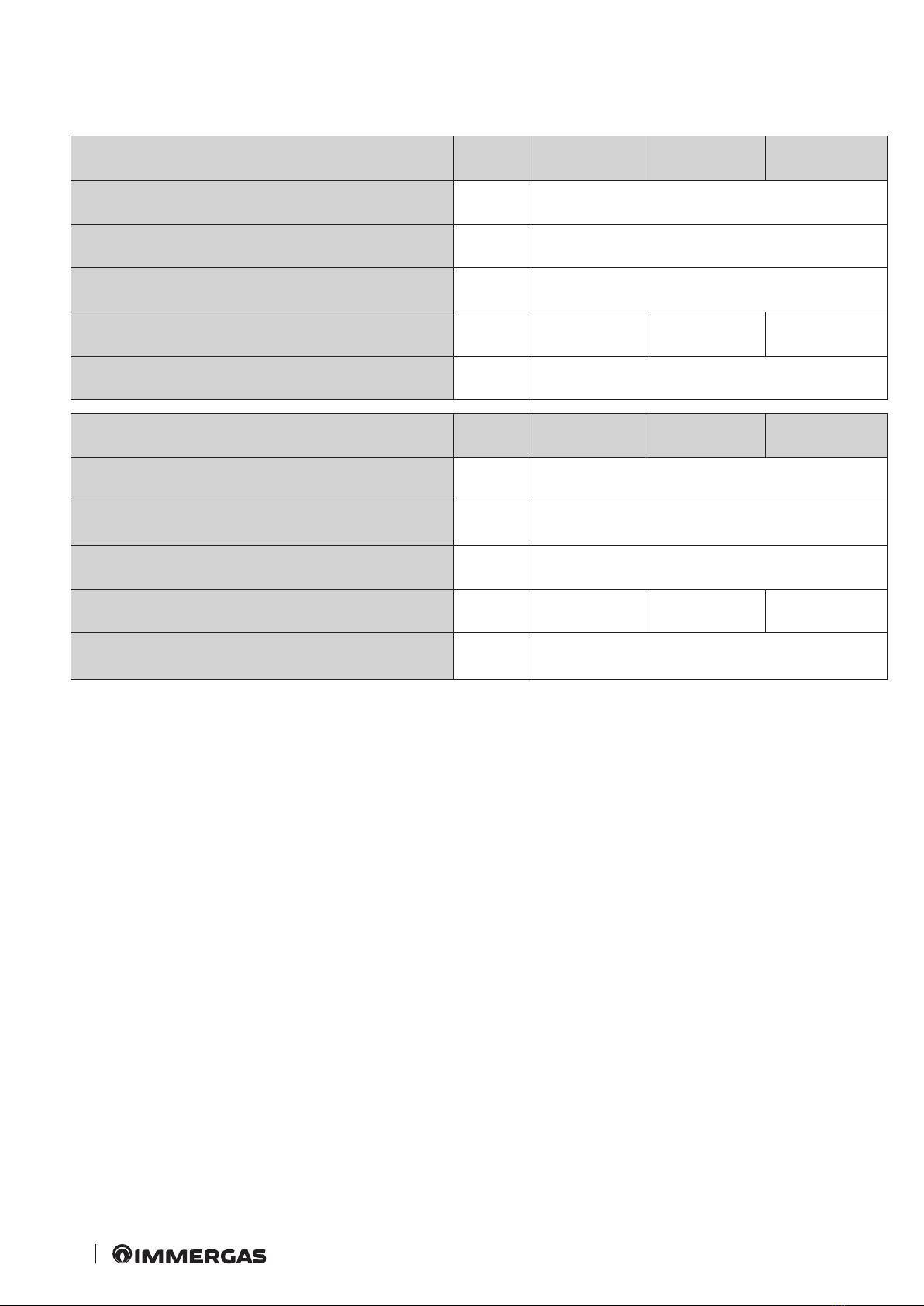
2 Outdoor unit specications................................................ 8
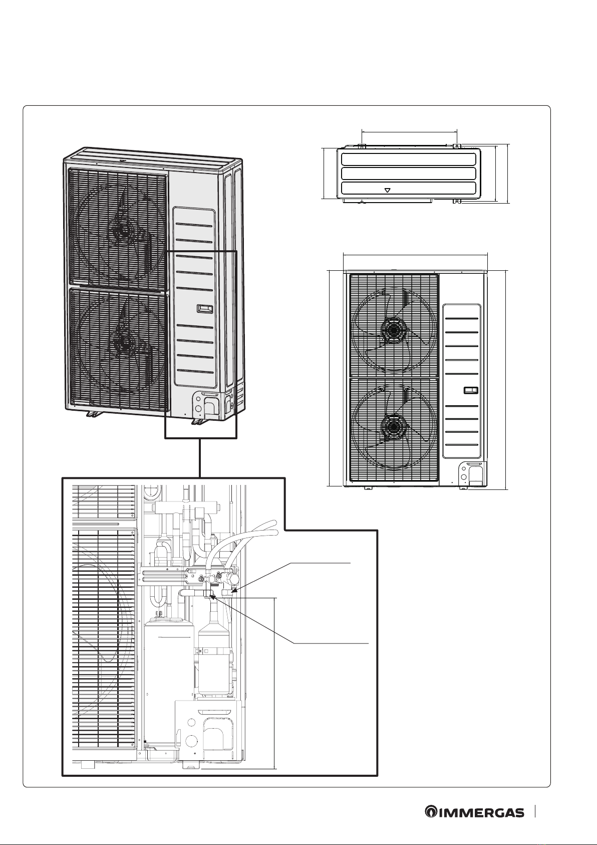
3 Main components................................................................ 9
4 Installation of the unit....................................................... 10
4.1 Outdoor unit installation position. ................................. 10
4.2 Installation guide near the sea. ........................................ 10
4.3 Handling by means of ropes............................................. 11
4.4 Required spaces.................................................................. 12
4.5 Installing the outdoor unit. .............................................. 14
4.6 Mount of outdoor unit...................................................... 14
4.7 Drainage of the outdoor unit. .......................................... 15
4.8 Positioning the unit in a rigid climate.............................16
5 Electrical connections....................................................... 17
5.1 General conguration of the system............................... 17
6 Connection of the cable.................................................... 19
6.1 Power cable specications. ............................................... 19
6.2 Specications of the connection cables (commonly
used). .................................................................................. 20
6.3 Specications of single-phase terminal block................ 20
6.4 Specications of three-phase terminal block................. 20
6.5 Power cable connection diagram..................................... 21
6.6 Connection of power terminal block.............................. 25
6.7 Earthing. ............................................................................. 25
6.8 How to connect extension cables..................................... 26
7 Checking correct earthing................................................ 28
8 Installation of chiller lines. ............................................... 29
8.1 Geometric limits of the Chiller lines and Examples of
installation. ......................................................................... 29
8.2 Selection of refrigerant pipe. ............................................ 30
8.3 Keep the refrigerant pipe clean and dry.......................... 30
8.4 Cutting and aring of pipes.............................................. 30
8.5 Choose the insulation of the refrigerant pipe. ............... 32
8.6 Insulating the refrigerant pipe. ........................................ 32
8.7 Pipe welding. ...................................................................... 33
8.8 Pressure test and search for leaks. ................................... 34
8.9 Vacuuming and dehydration of the pipes and the
indoor unit.......................................................................... 35
8.10 Relling the refrigerant charge. ....................................... 37
8.11 Relling the refrigerant charge. ....................................... 37
8.12 Adding refrigerant............................................................. 38
8.13 Closing the valve stem....................................................... 40
8.14 Opening the valve stem.....................................................40
9 Cooling cycle diagrams..................................................... 41
9.1 Diagram. ............................................................................. 41
10 Wiring diagram.................................................................. 42
10.1 Single-phase wiring diagram............................................ 42
10.2 ree-phase wiring diagram............................................ 43
11 Microswitch and key function settings........................... 44
11.1 Testing operations.............................................................. 44
12 “Pump down” execution................................................... 47
12.1 Purpose of “Pump down”.................................................. 47
12.2 Important warnings for “Pump down” execution......... 47
12.3 Pouring the refrigerant into an external cylinder
before carrying out the pump down ............................... 48
13 Completion of installation................................................ 49
14 Final inspections and test operation. .............................. 50
14.1 Final inspections and test operation ............................... 50
14.2 Test operation..................................................................... 50

3
e manufacturer declines all liability due to printing or transcription errors, reserving the right to make any modications to its
technical and commercial documents without forewarning.
e company IMMERGAS S.p.A., with registered oce in via Cisa Ligure 95 42041 Brescello (RE), declares that the design, manu-
facturing and aer-sales assistance processes comply with the requirements of standard UNI EN ISO 9001:2015.
For further details on the product CE marking, request a copy of the Declaration of Conformity from the manufacturer, specifying the
appliance model and the language of the country.
Dear Customer,
Congratulations for having chosen a top-quality Immergas product, able to assure well-being and safety for a long period of time. As an
Immergas Customer, you can also count on a qualied Aer-sales service, prepared and updated to guarantee constant eciency of your
heat pump. Read the following pages carefully: you will be able to draw useful tips on the proper use of the device, compliance with which
will conrm your satisfaction with the Immergas product.
For assistance and routine maintenance, contact Authorised Service Centres: they have original spare parts and are specically trained
directly by the manufacturer.
Correct disposal of the product
(Waste electrical and electronic equipment)(Applicable in Countries with separate waste collection systems)
When this symbol is applied on the product, on the accessories or on its documentation, it means that the product and relative electronic
accessories must not be disposed of with other waste at the end of its life cycle. To avoid damaging the environment or health due to in-
correct waste disposal, the user is recommended to separate the product and the above-mentioned accessories from other types of waste
and to recycle them responsibly by sending them to authorised facilities in compliance with local standards.
Household users, as an alternative to the autonomous management referred to above, can deliver the equipment they wish to dispose of
to the retailer when purchasing a new equivalent type of equipment. It is possible to deliver free of charge the electronic products with
dimensions of less than 25 cm that have to be disposed to retailers of electronic products with a sales area of at least 400 m2.
Corporate users (companies and professionals) should contact their supplier and verify the terms and conditions of the purchase con-
tract. is product and relative electronic accessories must not be disposed of together with other commercial waste.

4
GENERAL WARNINGS
• Carefully follow the precautions listed below as they are crucial to guarantee the safety of the product.
ATTENTION:
- Before carrying out service operations or accessing the internal components of this Out-
door Condensing Unit, it is essential to disconnect the power supply.
- Make sure that installation and performance tests are carried out by qualied personnel.
- Observance of all the precautions, warnings and indications given in this manual are essential
to prevent serious damage to the system and injuries to people.
•Carefully read the content of this manual before installing the device and keep it in a safe place so that it can be easily available for
consultation by the user.
•For greater safety, the installer should always read everything contained in this manual with the utmost attention.
•Store the use and maintenance manual in a safe place and remember to hand it over to the new owner should the device be sold or
transferred.
•is manual explains how to install the condensing unit. e use of indoor units equipped with dierent and therefore incompatible
control systems as well as being able to cause damage to the appliance causes the immediate invalidation of the manufacturer's war-
ranty. e manufacturer will not be held liable for damage resulting from the use of the appliance with units not compatible with it.
•e manufacturer declines all responsibility for any damage due to modications not previously authorized by itself in writing and/or
errors in the electrical and/or hydraulic and/or refrigerator connection of the appliance. Failure to comply with these instructions or
with the requirements set forth in the “Operating limits” table, including those in the manual, immediately invalidates the warranty.
•Failure to comply with the instructions indicated in the production specications immediately invalidates the warranty.
•Do not use the device if you notice any damage on it or if you perceive something strange, such as a loud noise or burnt smell.
•To prevent electrocution, re or injury, always switch o the unit, disable the protective switch and, if smoke escapes, if the unit is
extremely noisy or the power cable is overheated, contact the Authorised Technical Service Centre.
•e appliance as well as the electrical connections, the refrigeration lines and the protective devices must be inspected at regular
intervals. All inspections must be performed only by qualied personnel.
•e unit contains moving and electric parts which must always be kept out of the reach of children.
•Do not have unauthorised personnel attempt to repair, move, modify or reinstall the unit. ese operations could cause damage to
the product, electric shocks and re.
•Do not place liquid containers or other objects on the unit.
•All the materials used to manufacture and package the condensing unit are recyclable.
•e packaging material and the dead batteries of the remote control (optional) must be disposed of in compliance with local standards.
•e refrigerant in the condensing unit must be disposed of as special waste. At the end of its life, the device must be disposed in a
collection facility or returned to the shop so that it can be disposed of correctly and safely.
•Wear protective gloves to unpack, move, install and repair the unit to avoid getting injured by the edges of the appliance.
•Do not touch the internal parts (water pipes, refrigerant pipes, heat exchanger, etc.) while the unit is operating. If an internal part
needs to be adjusted, stop the unit, leave it as long as necessary to cool o and make sure to put on protective gloves.
•In case of refrigerant leaks, try not to come into contact with the refrigerant as this could cause serious injury.
•If the appliance is installed in a closed room, consider adequate ventilation to avoid a leak level beyond the maximum allowed limit.
•In that case, there is the risk of death by suocation.
•Make sure to dispose of the packaging materials quickly and safely. Otherwise the nails, the plastic and the timber of which it is made
could represent a serious danger of injury for the children.
•e device must be inspected upon receipt. If you notice any damage, DO NOT INSTALL THE PRODUCT and immediately report
any damage to the carrier or dealer (the purchase may have been made from a wholesaler or a sales agent).

5
•To ensure the possibility of carrying out any maintenance or repair operations around the appliance, our units must be installed
according to the clearance spaces. If the units are installed without complying with the procedures described, all the additional costs
that may arise from the use of shas, scaolding, stairs, etc. that are necessary to access the appliance (in SAFETY CONDITIONS, as
prescribed by the current Accident Prevention Regulations) will be CHARGED to the customer also for the interventions performed
during the warranty period.
•Always make sure that the power supply complies with local safety standards.
•Check that the supply voltage and frequency comply with the specications and that there is sucient input power to guarantee
operation of any other household appliance connected to the same power lines. Always make sure that the on-o switches and circuit
breakers are adequately sized.
•Always check that the electrical connections (arrangement and section of cables, cable lugs, protection devices, etc.) comply with
the electrical specications and with the instructions in the wiring diagram. Always check that all of the connections comply with
the regulations applicable to installation of the air/water heat pumps. All devices connected to the power supply line must be able to
disconnect automatically in the presence of overvoltage.
•e ground connection must not be made on the cables of telephone lines, gas pipes, pipes where water can ow, lightning protection
systems or for the absorption of peaks. Otherwise, or if made incorrectly, the earth connection could cause electric shock or re.
•Install both a dierential switch (circuit breaker) and a magnetothermic switch sized as prescribed by the local regulations in force.
•Failure to do so, would result in the risk of electrocution and re.
•Make sure that condensate exits properly from the unit even in case of low outside temperature. Both the drain pipe and the coolant/
air exchanger heater must be made in such a way that the condensate contained in them cannot freeze and clog them. If the drain is
not done properly for release of condensate, the unit could be damaged by ice blocks and the system could be stopped.
•Install the power cable and the communication cable with the indoor unit at least one meter from each electrical equipment.
•Protect the appliance against mice or other rodents. ey could gnaw on cables and other electrical components causing malfunction,
development of fumes and re. Inform the customer to keep the area around the unit clean.
•e electric heater must not be disassembled or altered by the user or installer.
•is appliance is not intended to be used by persons (including children) with reduced physical, sensory or mental capabilities or
lacking experience and the necessary knowledge, unless they are supervised or trained on use of the appliance by someone in charge
of their safety. Children must be supervised to make sure they do not play with the appliance.
•For use in Europe: this appliance may be used by children at least 8 years old or by persons with reduced physical, sensory or mental
capabilities or lacking experience and basic notions, as long as they are supervised or properly trained on safe use of the appliance
and are aware of the risks posed by it. Children must be supervised to make sure they do not play with the appliance. e appliance
must not be cleaned and serviced by children without the supervision of an adult.
•Make sure not to modify the power cable, to make extensions or connections with several wires.
•Poor quality connections or insulation, or exceeding the current limit, could cause shock and re.
•If extensions need to be made due to damage along the power line, refer to the chapter “How to connect extension power cables” in
the installation manual.

6
SAFETY SYMBOLS USED.
GENERIC HAZARD
Strictly follow all of the indications next to the pictogram. Failure to follow the indications can generate hazard situa-
tions resulting in possible harm to the health of the operator and user in general.
ELECTRICAL HAZARD
Strictly follow all of the indications next to the pictogram. e symbol indicates the appliance’s electrical components
or, in this manual, identies actions that can cause an electrical hazard
WARNING FOR INSTALLER
Read the instruction booklet carefully before installing the product.
NOTE FOR INSTALLER
Indicates useful tips or additional information for the installer.
WARNING FOR USER
Read the instruction booklet carefully before using the product.
READ AND UNDERSTAND THE INSTRUCTIONS
Read and understand the appliance’s instructions before performing any operation, carefully following the indications
provided.
INFORMATION
Indicates useful tips or additional information in general.
SAFETY GLOVES
PERSONAL PROTECTIVE EQUIPMENT.
SAFETY GOGGLES
SAFETY FOOTWEAR
e user must not dispose of the appliance at the end of its service life as municipal waste, but send it to appro-
priate collection centres.

7
1
1PRODUCT SPECIFICATIONS.
1.1 PRODUCT RANGE.
e products described in this booklet are:
Single-phase version
•UE AUDAX PRO 12 V2
•UE AUDAX PRO 14 V2
•UE AUDAX PRO 16 V2
ree-phase version
•UE AUDAX PRO 12 V2 T
•UE AUDAX PRO 14 V2 T
•UE AUDAX PRO 16 V2 T
1.2 ACCESSORIES.
Keep the supplied accessories at hand until installation is complete.
Deliver the installation manual to the customer at the end of the
installation. e amounts are indicated in brackets.
e condensing outdoor unit of the basic indoor heat pump works
depending on the outdoor climate.
Installation manual (1) Drain plug (2) Rubber feet (4) Drain plug (3)

8
2OUTDOOR UNIT
SPECIFICATIONS.
Model (Single-phase) Unit UE AUDAX PRO
12 V2
UE AUDAX PRO
14 V2
UE AUDAX PRO
16 V2
Power supply - 1P, 220~240 CA, 50 Hz
Weight (net /gross) kg 100.0/109.5
Net dimensions (LxHxP) mm 940 x 1.420 x 330
Sound pressure level (central heating /cooling) dB(A) 50 /50 50 /52 52 /54
Operating eld (central heating /cooling) °C -25~35/10~46
Model (ree-phase) Unit UE AUDAX PRO
12 V2 T
UE AUDAX PRO
14 V2 T
UE AUDAX PRO
16 V2 T
Power supply - 3P, 380~415 CA, 50 Hz
Weight (net /gross) kg 101.5/111.0
Net dimensions (LxHxP) mm 940 x 1.420 x 330
Sound pressure level (central heating /cooling) dB(A) 50 /50 50 /52 52 /54
Operating eld (central heating /cooling) °C -25~35/10~46
With external temperatures of -25 °C ~-20 °C operation is possible
but performance is not guaranteed.

9
2
620
330
360
384
940
1395
1420
532
General dimensions in mm.
3MAIN COMPONENTS.
Gas side pipe
Liquid side pipe

10
3
4INSTALLATION OF THE UNIT.
4.1 OUTDOOR UNIT INSTALLATION POSITION.
e installation site must be chosen in agreement with the user
and taking into account some further specications.
- e outdoor unit must not be positioned on its side or upside
down, as the lubricating oil of the compressor could enter the
cooling circuit and seriously damage the unit.
- e chosen location must be dry and ventilated, but not directly
exposed to sunlight and strong winds.
- e air must be able to circulate freely through the appliance.
- Choose a position where the noise of the condensing unit during
operation or the discharge air do not disturb neighbours.
- e selected position should allow easy connection of both cables
and pipes.
- e support surface must be at, stable, sturdy at least enough to
withstand the weight of the appliance and not such as to generate
any useless noise and vibrations.
- Position the outdoor unit so that the air ow is directed outdoors.
- ere must be no trees or animals nearby the appliance which
could impair its operation.
- e device must be located at a sucient distance from radio
and/or stereo systems as well as from computers, etc.
4.2 INSTALLATION GUIDE NEAR THE SEA.
Make sure to follow these guidelines for installation along the
sea coast.
1. Do not install the appliance where it is directly exposed to sea
water or breeze.
- Install the product behind a structure (like a building) which
can block the sea breeze.
- Even when it is inevitable to install the appliance along the
seacoast, make sure it is not exposed directly to the sea breeze
by installing a protective wall.
2. Consider that the saline particles which adhere to the external
panels must be suciently washed.
3. Since residual water at the bottom of the outdoor unit signif-
icantly promotes corrosion, make sure the slope does not aect
drainage.
- Keep the oor level so that rain does not make any puddles.
- Be careful not to obstruct the drain hole with foreign substances
4. When the appliance is installed on the beach, clean it regularly
with water to remove any attached salinity.
5. Make sure to install the appliance where water can be drained
conveniently. In particular, make sure that the part of the base
drains well.
6. If the appliance is damaged during installation or maintenance,
make sure to restore it.
7. Regularly check the condition of the product.
- Check the installation site every 3 months and perform an
anti-corrosion treatment with grease and water-repellent wax
according to the conditions of the appliance.
- Take appropriate measures to cover the product when it needs
to be stopped for a long period of time, for example peak hours.
8. e product requires a special anti-corrosion treatment if
installed within 500 m from the sea.
For further information, contact the Authorised Technical As-
sistance Centre.
Sea breeze
Outdoor
unit
Sea Sea
Outdoor
unit
Sea breeze
Sea
Protective
wall
Sea breeze
Outdoor
unit
e protective wall must be built with solid and stur-
dy material capable of blocking the sea breeze and
its height and width must be 1.5 times larger than
those of the outdoor unit. (To guarantee ventilation,
the protective wall must be at least 700 mm from the
outdoor unit).

11
4
ATTENTION:
Depending on the condition of the pow-
er system, unstable voltage or power
supply may cause the components or
control system to malfunction (in places
that use electric generators, etc).
Do not install the appliance in the following places.
- Places where there is mineral oil or arsenic acid. Otherwise, the
plastic parts could corrode, damaging the appliance. e capacity
of the heat exchanger could be reduced with serious impacts on
the performance of the entire appliance.
- Places where corrosive gases are present, such as those exhaled
by ventilation pipes or ues. Copper pipes would be corroded
with subsequent refrigerant leaks.
- Places with the risk of leaks of combustible gases, carbon bres
or ammable dust. Places where thinners or petrol are handled.
ATTENTION:
is device must be installed according
to current electrical standards.
We suggest not to install it overhanging
but on the oor.
- In case of overhanging installation, the appliance must be rmly
anchored to the support structure.
- e water that drips from the drainage hose must always be able
to do so without any obstacle.
- When the appliance is installed cantilevered, it must be at least
2 m from the oor or in such a way that the heat emitted by the
unit does not come into direct contact with passers-by (Refer
to standards in force relating to structures in the construction
eld).
4.3HANDLING BY MEANS OF ROPES.
e appliance must be lied by slinging it with two 8 m long
ropes, as illustrated in gure 4. To avoid damages before liing,
it is advisable to place protective cloths between the ropes and
the appliance.
Depending on the model, the appearance of the device may dier
from that shown in the illustration.
Wire
rope
Protective
cloth

12
5
(Unità: mm)
300 o più
1.500 o più
Quando l'uscita dell'aria è opposta alla parete Quando l'uscita dell'aria è verso la parete
300 o più 600 o più
1.500 o più
2.000 o più
Quando 3 lati dell'unità esterna sono bloccati dalla
parete
La parte superiore dell'unità esterna e l'uscita
dell'aria sono verso la parete
600 o più
300 o più
1.500 o più 300 o più
La parte superiore dell'unità esterna e l'uscita
dell'aria sono opposte alla parete
Quando le parti anteriore e posteriore dell'unità
esterna sono verso la parete
4.4REQUIRED SPACES.
Installation of an outdoor unit.
(Unit: mm)
When the air outlet is opposite the wall When the air outlet is towards the wall
When 3 sides of the outdoor unit are blocked by the wall e top of the outdoor unit and the air outlet are towards
the wall
When the front and rear parts of the outdoor unit are
towards the wall
e top of the outdoor unit and the air outlet are oppo-
site the wall
300 or more
1500 or more
1500 or
more
2000 or more
300 or more1500 or
more
300 or
more
600 or more
300 or more
300 or more 600 or more

13
6
(Unità: mm)
1.500 o più
Quando l'uscita dell'aria è verso la parete
300 o più
300 o più 600 o più 600 o più 600 o più
Quando 3 lati dell'unità esterna sono bloccati dalla parete
300 o più1.500 o più
600 o più 600 o più
500 o più
500 o più
300 o più
300 o più
Quando le parti anteriore e posteriore dell'unità esterna sono
verso la parete
La parte superiore dell'unità esterna
1.500 o più 600 o più 3.000 o più 300 o più3.000 o più
Quando le parti anteriore e posteriore dell'unità esterna sono verso la parete
e l’uscita dell’aria sono opposte alla parete
Installation of several outdoor units.
(Unità: mm)
1.500 o più
Quando l'uscita dell'aria è verso la parete
300 o più
300 o più 600 o più 600 o più 600 o più
Quando 3 lati dell'unità esterna sono bloccati dalla parete
300 o più1.500 o più
600 o più 600 o più
500 o più
500 o più
300 o più
300 o più
Quando le parti anteriore e posteriore dell'unità esterna sono
verso la parete
La parte superiore dell'unità esterna
1.500 o più 600 o più 3.000 o più 300 o più3.000 o più
Quando le parti anteriore e posteriore dell'unità esterna sono verso la parete
e l’uscita dell’aria sono opposte alla parete
When 3 sides of the outdoor unit are blocked by the wall
(Unit: mm)
When the air outlet is towards the wall
300 or more1500 or
more
300 or more
300 or more
300 or more 600 or more
1500 or more
600 or more 600 or more
500 or more500 or more
600 or more
600 or more
When the front and rear parts of the outdoor unit are towards the wall
600 or more 300 or more3000 or more 3000 or more1500 or more
When the top of the outdoor unit and the air
outlet are opposite the wall
300 or more
ATTENTION:
To ensure the proper functioning of the
outdoor unit and accessibility from all
sides for maintenance, service and repair, it is
essential to leave the distances specied above.
e outdoor unit must be able to be main-
tained and repaired in conditions of safety (or
persons or objects).

14
7
8 9
(Unità: mm)
620
940
328
344
384
F
oro bullone di ancoraggio
Anchor bolt hole
(Unit: mm)
4.5 INSTALLING THE OUTDOOR UNIT.
e appliance must be installed on a rigid and stable base to pre-
vent any increase in noise or vibration. In particular if it is exposed
to strong winds and when installed overhanging, it must be xed
to a frame that is able to support its weight and that is adequately
xed to the load bearing structure (oor or wall).
e appliance must always be xed by means of anchor screws.
e anchor bolt must be at least 20 mm from the base
surface (Fig. 9).
ATTENTION:
- To prevent corrosion, it is necessary to
place rubber washers between the feet
of the appliance and the tightening
nuts screwed onto the anchor screws.
- A drainage channel must be built around the
base.
- When the appliance is to be installed on a
roof, it is necessary to ensure in advance that
the latter is able to withstand its weight and
that it is watertight.
4.6MOUNT OF OUTDOOR UNIT.
Outdoor unit installed on wall frame.
- e wall on which the frame is xed must be able to support the
weight of the outdoor unit plus that of the frame.
- It is advisable to x the frame in a point that is as close as possible
to any columns.
- Install adequate gaskets to reduce noise and residual vibration
transferred from the unit to the wall.
ATTENTION:
In case of installation of an air conveyor,
be careful not to damage the pipes with
the xing screws.
Fix the conveyor to the fan protection grid.
20mm
Bullone di
ancoraggio
Unità
esterna
basamento
Supporto
dell'unità
esterna
Supercie
Anchor bolt
Indoor
unit
Base surface
Mount of
outdoor unit

15
12 13
≥100 mm
Tappo di scarico x 3 pz.Connettore di scarico x 1 pz.
Foro di scarico Φ20 x 4 pz.
Lato scarico dell'aria
13mm
10
80
mm
11
4.7DRAINAGE OF THE OUTDOOR UNIT.
General Area
During heating operation, ice deposits may occur on the external
surface of the refrigerant-air exchanger.
To prevent the amount of these deposits from increasing too much,
the appliance performs defrosting cycles to melt those deposits.
e resulting water from this process is disposed of through the
drainage holes to prevent it from re-solidifying on the bottom of
the appliance when the external temperature is rather low.
- If for any reason it is impossible to allow this water to drain freely
it would be necessary.
- Leave the appliance raised by at least 100 mm with respect to
the support surface (Fig. 10).
- Insert the drain sleeve in one of the three drainage holes on the
bottom of the appliance and plug the other three with the drain
plugs supplied.
- Connect a hose to the drain hose that conveys the water to the
desired place.
- Make sure that no dust, debris and/or insects can enter this hose.
ATTENTION:
If the water produced by the outdoor
unit was not drained suciently, the
performance of the entire system would suer
a negative impact and the system itself could
be damaged.
Drain hole ø20 (4 pc)
Air exhaust side
Drain connector
(1 pc) Drain plug (3 pc)
1. All around the base of the unit, dig a water drainage channel
that can properly drain the water and condensate produced by
the unit.
2. To facilitate drainage, the unit can be installed on a concrete
prism base so that the unit is raised by at least 150 mm above
the walking surface.
3. e unit should be raised by at least 150 mm above the oor
to prevent its ooding in the event of heavy rain.
4. If the installation takes place in a snowy area, the unit should
be raised with respect to the oor of an altitude equal to at least
the height of the strongest foreseeable snowfall.
5. If the unit is installed overhanging (Fig. 13), it would be ap-
propriate to place a collection tray under it (not included in
the supply) that collects and drains in a controlled manner the
condensate that could drip from the appliance.
Area with intense snowfalls (natural drain)
Ice can build up when using the heat pump in central heating
mode. During de-icing (defrosting operation), the condensate
water must be drained safely. For the heat pump to work properly,
follow the instructions below.
- Leave more than 80 mm between the bottom of the outdoor unit
and the ground for the installation (Fig. 11).
- If the product is installed in a region with heavy snowfalls, leave
sucient space between the product and the ground (Fig. 14).
- When you install the product, make sure that the mount is not
positioned below the drain hole.
- Make sure that the drain water ows out correctly and safely.

16
Telaio
Terreno
Ne
ve stimata
Tettoia a prova
di neve
14
15
16
Snow-proof
roof
ATTENTION:
- In zones subject to heavy snowfalls,
the accumulated snow could block in
the air vents. To avoid this occurrence, install
a frame higher than the estimated level of
the snow. Furthermore install a snow-proof
roof to prevent the snow from piling up on
the outdoor unit.
- Potential accumulated ice on the base could
seriously damage the product (e.g. the shore
of a lake in very cold areas, the coastline, an
alpine region, and so on).
- In an area with heavy snowfall, do not in-
stall the drain plug and the drain cap in
the outdoor unit. It could cause ice to form
on the ground. erefore, take appropriate
measures to prevent the inconvenience.
4.8POSITIONING THE UNIT IN A RIGID CLIMATE.
To operate the appliance in low temperature outside
environmental conditions, follow the instructions
below.
- To avoid exposure to wind, install the unit with the intake side
facing the wall.
- Do not install the unit in a place where the intake side can be
directly exposed to the wind.
- To avoid exposure to the wind, install a deector on the delivery
side of the unit.
Frame
Estimated snowfall
Ground
- In areas subject to heavy snowfalls, it is very important to choose
an installation site where snow does not aect the unit. If nec-
essary, the coolant/air exchanger should also be protected from
snow (if necessary, build a side snow cover) (Fig. 15).
1. Create a canopy that also protects the sides of the unit.
2. Create a base that elevates the device from the oor by a
greater height at the height of the worst foreseeable snowfall.
- Prevent the unit from being even partially buried by snow.
- By turning the K6 switch to ON, the fan inside the device works
in such a way as to prevent snow from accumulating inside the
device itself.
- e outdoor unit must be installed considering the direction of
strong winds. erefore the side of the unit, and not the front,
should face the wind (Fig. 16).
Strong wind
Strong wind
Strong wind

17
17
1 fase
2 Conduttori
220-240V~
Terra
Cavo di comunicazione
Unità esterna Unità internaQuadro di distribuzione
Interruttore di
Protezione
Monofase
a 2 li
220 - 240 V~
Monofase
a 2 li
220 - 240 V~
Terra
5ELECTRICAL CONNECTIONS.
5.1 GENERAL CONFIGURATION OF THE SYSTEM.
Connection of power cable (single phase /2 wires).
Distribution board Outdoor unit Indoor unit
Communication cable
Earthing
Earthing
Single-phase
with
2 wires
220-240V~
Single-phase
with
2 wires
220-240V~
Protection switch
Single-phase
with
2 wires
220-240V~
Unit supply
voltage
System integrating
resistance supply voltage
ATTENTION:
- For service and emergency needs, the
electrical panel should be located near
the outdoor unit.
- e magnetothermic switch must be
equipped with protection against overcur-
rents and against earth leakage.

18
18
Trifase
a 4 li
380 - 415 V~
Terra
Cavo di comunicazione
Unità esternaScheda di distribuzione
Interruttore di
Protezione
Unità interna
Trifase
a 4 li
380 - 415 V~
Trifase
a 4 li
380 - 415 V~
Terra
Connection of power cable (three-phase /4wires).
Distribution board Outdoor unit Indoor unit
Communication cable
Earthing
Earthing
ree-phase
with
4 wires
380-415V~
Protection switch
Single-phase
with
2 wires
220-240V~
Single-phase
with
2 wires
220-240V~
Unit supply
voltage
System integrating re-
sistance supply voltage
ATTENTION:
- For service and emergency needs, the
electrical panel should be located near
the outdoor unit.
- e magnetothermic switch must be
equipped with protection against overcur-
rents and against earth leakage.

19
6CONNECTION OF THE CABLE.
6.1 POWER CABLE SPECIFICATIONS.
Single-phase unit
Outdoor unit
Rated Values Tolerable Voltage Range MCA MFA
Hz Volt Min Max Minimum Circuit
Current
Fuse rating
UE AUDAX PRO 12 V2 50 220-240 198 264 28 A 35 A
UE AUDAX PRO 14 V2 50 220-240 198 264 30 A 37.5 A
UE AUDAX PRO 16 V2 50 220-240 198 264 32 A 40 A
- e power cable is not supplied with the condensing unit.
- e power cables must be suitable for outdoor installation
and have at least one exible polychlorophene sheath (Code
IEC:60245 IEC 57 /CENELEC:H05RN-F).
- is appliance complies with standard IEC 61000-3-12.
ree-phase.
Outdoor unit
Rated Values Tolerable Voltage Range MCA MFA
Hz Volt Min Max Minimum Circuit
Current
Fuse rating
UE AUDAX PRO 12 V2 T 50 380-415 342 457 10 A 16.1 A
UE AUDAX PRO 14 V2 T 50 380-415 342 457 11 A 16.1 A
UE AUDAX PRO 16 V2 T 50 380-415 342 457 12 A 16.1 A
- e power cable is not supplied with the condensing unit.
- e power cables must be suitable for outdoor installation
and have at least one exible polychlorophene sheath (Code
IEC:60245 IEC 66 /CENELEC:H07RN-F).
- is appliance complies with standard IEC 61000-3-12. e
device complies with the dictates of the IEC 61000-3-12 stand-
ard provided that the short-circuit power Ssc sia ≥3.3 MVA at
the interface point between the user's network and the public
network. It is the responsibility of the installer or user to contact
the electricity supplier to ensure that the appliance is connected
to a power supply with Ssc ≥3.3 MVA].

20
6.2 SPECIFICATIONS OF THE CONNECTION CABLES
COMMONLY USED.
Communication cable
Two wires of 0.75~1.5mm
- The connection cable must be of type H07RN-F or type
H05RN-F.
19
- If the outdoor unit is installed in a computer room, in a network
room or in a server room, or where there is the risk of disturbance
of the communication cable, use a double-shielded communi-
cation cable (aluminium tape/polyester +copper braid) type
FROHH2R.
6.3SPECIFICATIONS OF SINGLEPHASE TERMINAL
BLOCK.
N
L
2(N)
1(L)
Alimentazione in CA: Vite M5 Comunicazione: Vite M4
15 12
9,7
6,7
AC Power: Screw M5 Communication: Screw M4
6.4SPECIFICATIONS OF THREEPHASE TERMINAL
BLOCK.
Alimentazione in CA: Vite M4 Comunicazione: Vite M4
9,7
6,7
N
L3(T)
L2(S)
L1(R)
2(N)
1(L)
9,95 11,55
AC Power: Screw M5 Communication: Screw M4
Other manuals for UE AUDAX PRO V2
1
This manual suits for next models
6
Other Immergas Heat Pump Accessories manuals