Axiom Prime KidWalk User manual

INSTRUCTIONS FOR USE
KidWalk
KidWalk II
Dynamic walking aid
Supplier
Manufactured by
Prime Engineering
A Division of Axiom Industries, Inc.
70111KWOM

KidWalk/KidWalk II 2

KidWalk/KidWalk II
1
TABLE OF CONTENTS
These instructions for use are organised into the following sections:
Description Page
• General information 2
Intended use/limitations of use 2
Maintenance 2
Cleaning and care 3
Training 3
Quality 3
Safety 3
• Product illustration and technical data 6
• Parts list 7
• Assembly instructions 8
• Measurements & initial setup 11
• Initial adjustments 13
• Positioning the user 15
• Use 17
• Disposal 17
• Materials used 17
• Exit of the user/transport and storage 18
• Accessories 19
• Limited warranty 27
In addition, we have included a number of notes to assist in the as-
sembly and use of the KidWalk/KidWalk II.
If you have any questions or require further assistance, please
contact your supplying dealer for assistance or contact us at
1-800-827-8263.

KidWalk/KidWalk II 2
Information: - Date of the last update: 2018-05-08
- Please read this document carefully.
- Follow the safety instructions.
This item should be tted by an experienced clinician or technician. This
document contains important information that must be passed on to the
user at delivery.
Before assessing for the proper positioning of the KidWalk/KidWalk II, ensure
that the user is sitting in the seat and has ample foot contact with the oor to allow
for proper ambulation.
Intended use/restrictions on use
Intended use
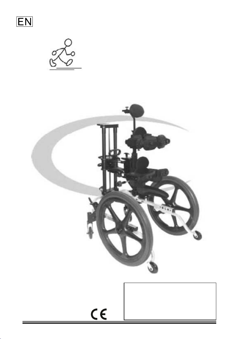
The KidWalk/KidWalk II system from Prime Engineering, Inc. is designed to
provide the user with the important benet of independently exploring the environ-
ment through hands-free mobility.
It supports gait training in case of diseases or the consequences of injuries that
involve both a disturbance in the locomotor system and coordination/balance dis-
turbances, even in early intervention.
However, diagnoses that indicate the use of the KidWalk are not limited to the
above and include for instance cerebral palsy, muscular dystrophy, paraplegia,
spinal muscular dystrophy, Downs syndrome, spina bida and many more. Cont-
raindications are not known.
The product is suitable for re-use.
Usage restrictions
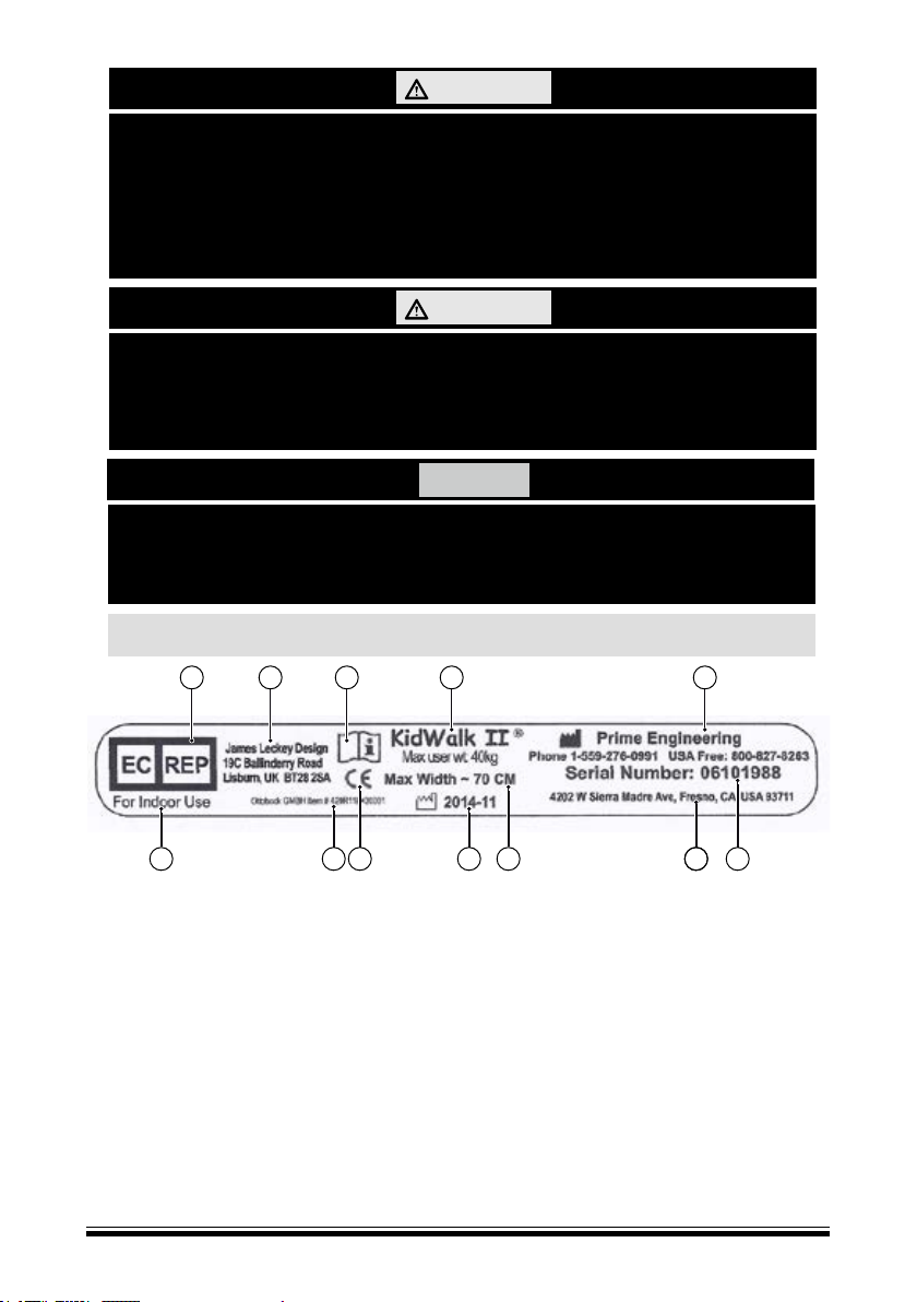
• The product is intended for indoor use only.
• Only for use in institutions or facilities for people with disabilities.
• Before using the KidWalk II, check if the doors have a minimum width of
70 cm.
• Use on level surface only.
• The KidWalk is limited to a seat height of 9 – 22” (23 – 56 cm) and a user
weight of 65 pounds (30 kg).
• The KidWalk II is limited to a seat height of 15 – 28" (38 – 71 cm) and a
user weight of 90 pounds (40 kg).
MAINTENANCE
Before each use (including reuse):
Visually check for loose or worn screws and nuts.
Keep moving parts free of dirt and rust to allow for free movement.
All fabrics should be hand washed with mild soap and water. Then allow to air dry.

KidWalk/KidWalk II
3
TRAINING
If for any reason you should require additional training regarding the assembly and
use of the KidWalk/KidWalk II, please contact your authorised dealer or Prime
Engineering, Inc. at the numbers specied in these instructions.
QUALITY
In keeping with our policy of continuous improvement, we reserve the right
to modify designs without prior notice.
All rights reserved.
CLEANING AND CARE
Seat and pad fabric may be cleaned with a neutral detergent and warm water, a
neutral disinfectant and/or a single use wipe.
Cleaning agents including alcohols and phenols should not be used.
All hardware may be cleaned with common household cleaners and a soft cloth.
Store in dry environment.
Annually:
Unit should have all fasteners tightened properly by a suitably qualied and com-
petent technician.
The product was designed for an average service life of approximately ve years.
To obtain the full service life, the instructions and measures described in these
instructions for use must be followed and carried out.
SAFETY
Explanation of warning symbols
Warning regarding possible serious risks of ac-
cident or injury
Warning regarding possible risks of accident or
injury
Warning regarding possible technical damage
WARNING
CAUTION
NOTICE

KidWalk/KidWalk II 4
• Make sure that the ngers do not get into the unused wheel brackets (see Fig.
3). Do not remove the installed cover caps.
• Make sure that the ngers do not get into the unused holes of the wheel lock.
Do not remove the installed cover caps.
• The anti-tipper must be properly adjusted to the large wheels.
• The KidWalk can tip over forwards in case of positioning too far forward. This
is therapeutically intended to give the user the required feedback in case of an
unwanted gait pattern. The anti-tipper is mandatory to prevent the user from
tipping forward with the KidWalk.
• While the user is in the system, the belts must be kept fastened.
• The locking pin to attach the adapter column must be engaged.
• The wheel lock must be properly adjusted to the big wheels.
• All adjustment knobs must be secure.
• Never leave the user of the KidWalk/KidWalk II unattended in the device.
• Wheel lock: The wheel lock only helps with placing the user in the product.
It cannot be operated by the user itself. The user may never use the product
unattended, on slopes or near stairs.
• Note that a lack of knowledge of the instructions for use can lead to injuries
due to user error. Read the instructions for use rst. Prior to use, familiarise
yourself with the handling and function of the product and practice using it.
• To avoid pinching or other injuries, make sure that the user does not reach
into moving parts.
• To avoid pinching or other injuries, make sure that the ngers do not get into
the wheels.
WARNING
WARNING
WARNING
CAUTION
CAUTION
CAUTION

KidWalk/KidWalk II
5
• Do not adjust the system too narrow at the height of the hip.
• Before using the KidWalk/KidWalk II, check if the width of the doors is suf-
cient for passing through (KidWalk II more than 70 cm).
• The product is for indoor use only.
• The upholstery is not highly ammable, but can catch re. Therefore the ut-
most caution must be exercised in the vicinity of an open ame.
• Keep away from all ignition sources, especially lit cigarettes.
• Avoid hypothermia or burns through contact with components. Do not expose
the product to any extreme temperatures (e. g. direct sunlight, sauna, extreme
cold).
• Do not use the product in salt water.
• Avoid damage to the product due to sand or other particles of dirt.
NAMEPLATE
A Symbol for the authorised EU representative
B Authorised EU representative
C Read the instructions for use before use. Max. load capacity
D Product name, manufacturer information/address
E Manufacturer information, serial number
F Serial number of the manufacturer, European article number
G Address of the manufacturer. Read instructions for use prior to use.
H Max. width of the product
I Date of manufacture YYYY-MM
J CE marking – product safety in accordance with EU directives
K Ottobock article number
L For indoor use only
The nameplate is located on the inside of the frame below the adapter column.
CAUTION
CAUTION
NOTICE
FL K J I H GG
EDCB
A

KidWalk/KidWalk II 6
TECHNICAL DATA
KidWalk/KidWalk II
Illustration of the
KidWalk/KidWalk II with optional encompassing thoracic pad
Technical data Size 1 Size 2
Age 1 – 7 years 5 – 12 years
Max. user weight 30 kg 41 kg
Seat height – inside leg length 230 – 560 mm 380 – 710 mm
Hip width 140 – 235 mm 180 – 290 mm
Trunk width 165 – 255 mm 220 – 370 mm
Armpit height 245 – 410 mm 300 – 560 mm
Trunk depth, standard 102 – 165 mm 140 – 216 mm
Hip depth, standard 89 – 152 mm 127 – 178 mm
Overall width 610 mm 700 mm
Max. overall length 920 mm 1010 mm
Max. overall height 1190 mm 1320 mm
Wheels 500 mm (20“) 600 mm (24“)
Casters 100 mm (4“) 125 mm (5“)
Product weight: approx. 21.6 kg approx. 24 kg
Upper section weight approx. 10.7 kg approx. 12.1 kg
Lower section weight approx. 10.9 kg (wheels 4.4 kg) approx. 11.9 kg (wheels 4.8 kg)
Turning radius 1080 mm 1120 mm

KidWalk/KidWalk II
7
Component identication
Adapter column
Height adjustment/
release handle
Fine adjustment
handle
Rotary knob for
angle adjustment
Wheel lock
Swivelling
luminous caster
wheels
Head pad
Encompassing
thoracic support
Flip-up front thoracic
support
Auto centring
Pelvic guides
Seat
Wheel
Anti-tipper
Axle receiver loca-
tions
PARTS LIST
The KidWalk/KidWalk II comes preassembled in one carton.
The carton contains:
Quantity Description
1 Base frame
1 Adapter column
2 Wheels
2* Axles
2* Axle spacers
*The axles and axle spacers are in a sealed poly bag.
Optional items:
Other optional items may be packed in the box. Make sure to identify any optional compo-
nents in the box and the instructions for use that belong with them.

KidWalk/KidWalk II 8
ASSEMBLY INSTRUCTIONS
Set-up and assembly of the KidWalk/Kid-
Walk II is easy when these directions are
followed.
First:
Open carton, remove and identify the following
assemblies and components.
ABase frame with anti-tipper
BAdapter column with self-centring pelvic
guide
CWheels (2)
DBag containing axles and spacers
• Optional accessories (if ordered)
Assembly:
• Place the base frame onto a level surface
as shown in Fig. 1.
• Remove axles and axle spacers from plas-
tic bag. From the side with the recessed
bearing, insert the axle into the wheel (Fig.
2). Push in the button at the end of the
axle during this process so the axle can
slide all the way through the wheel bea-
ring. Assemble one spacer onto the axle
at the back of the wheel as shown in Fig. 2
while holding the axle button in.
• Attach the wheel with the quick-release
axle to the centre position of the wheel
brackets on the base frame (Fig. 3). Re-
peat procedure on opposite side.
Information: Always use the centre hole
for initial setup.
The wheel locks and anti-tipper are preset
for the centre axle position.
B
A D
C
Fig. 1
Recessed
side of
wheel
Axle pin
(button end)
Fig. 2
Wheel
spacer
Wheel
attachment
device Fig. 3
• When connecting the upper section to the
lower section, be sure to hold the upper
section on the adapter column and below
the seat.
CAUTION

KidWalk/KidWalk II
9
Encompassing thoracic support
• Slide the extension tube through the cor-
responding adapter on the encompassing
thoracic support (Fig. 6).
• Then slide the extension tube into the up-
per end of the receiver tube. Set the pads
at proper heights and tighten both adjust-
ment screws (Fig. 6).
• Pull the locking pin for the adapter column
on the rear of the base frame and rotate it
one-quarter turn so it locks (Fig. 4).
• Set the adapter column onto the guide
pins on the base frame (Fig. 5). Rotate
the locking pin until it engages in the
adapter column. Make sure that the re-
lease pin is fully engaged and the adap-
ter column is rmly connected to the base
frame. If the adapter column can be lifted
off the base frame, continue turning the
locking pin until it engages in the adapter
column.
ASSEMBLY INSTRUCTIONS
Assembly for optional accessories:
Adapter
column
Locking
pin
Guide
pins
Fig. 4
Base frame
Adapter
column
Fig. 5
Note: If you have other optional accessories that are not listed here, the instruc-
tions for their installation and use will be packed with the item.
Encompassing
thoracic support
Extension tube
Adjustment
screws
Receiver tube
Fig. 6
• Make sure that the adapter column is al-
ways rmly attached to the base frame.
• The KidWalk/KidWalk II must only be
used with the anti-tipper and seat. Do not
remove the anti-tipper and never use the
system without the anti-tipper and seat.
CAUTION

KidWalk/KidWalk II 10
ASSEMBLY INSTRUCTIONS
Headrest
• Insert the headrest in the extension tube;
the pad has to face forward. Then tighten
the adjustment screw securely (Fig. 7).
Swivelling casters
(Not available for KidWalk II)
• Remove the anti-tipper arms from the
base frame. In order to do so, press in the
position setting push button “A” (Fig. 8)
and pull the anti-tipper out as far as possi-
ble. Then press the retaining button “B” at
the end of the anti-tipper and slide the arm
completely out of the base frame.
• Press in the button "B" on the swivelling
casters and slide them into the holder of
the anti-tipper adapter (Fig. 9). Press but-
ton “A” and slide the tube back until the
button snaps into the centre hole in the
anti-tipper adapter.
Height
adjustment
screw
Fig. 7
Pull out
Button "A"Button "B"
Fig. 8
Button "A"
Push in
Button "B"
Fig. 9
• Only use the KidWalk/KidWalk II with
the corresponding anti-tipper or the swi-
velling casters. Always reinsert the anti-
tipper in the frame when the swivelling
casters are no longer used (swivelling
casters not available for the KidWalk II).
CAUTION

KidWalk/KidWalk II
11
MEASUREMENTS & INITIAL SETUP
Measurements:
The following measurements should be taken and
recorded for the setup of the KidWalk/KidWalk II:
• Inseam __________ inch (cm)
• Hip width __________ inch (cm)
• Chest width __________ inch (cm)
• Thoracic height* __________inch (cm)
• Head height* __________ inch (cm)
*Thoracic height and head height measurements
should be taken from the top of the inseam. These
measurements are needed to adjust the optional en-
compassing thoracic support and/or head pad/head-
rests available for the KidWalk/KidWalk II.
KidWalk/KidWalk II initial adjustments:
Seat height:
• Using the height adjustment/release handle or
the ne adjustment handle (Fig. 10), adjust the
seat height to 1 inch (2.5 cm) higher than the
inseam measurement.
• To raise the seat with the height adjustment/
release handle, press down on the top of the
adapter column with one hand while pulling up
the height adjustment/release handle with the
other hand.
• To raise the seat using the ne adjustment, put
your hand through the ne adjustment handle
and pull the lower section of the handle up (Fig.
10). Each time you squeeze the ne adjustment
handle, the seat will rise up by one-half inch
(1.3 cm).
• To lower the seat, simply press down slightly
on the height adjustment/release handle (Fig.
10). Only minimal force is needed to lower the
seat on the adapter column. Do not push the
seat down too hard. As soon as the height ad-
justment/release handle is no longer pressed
down, the seat remains at the current height.
(Seat cannot be lowered while bearing weight.)
Height adjustment/
release handle
Fine adjustment
handle
Fig. 10
Entry position

KidWalk/KidWalk II 12
Other items:
Make sure that all supports are set to a suitable
height and width for the user. Adjust any optional
items to match the measurements for height and
width per the instructions included here.
NOTICE: Set all depth-adjustable pads so far for-
ward that the user ts into the system when the
pads are ipped down.
MEASUREMENTS & INITIAL SETUP

KidWalk/KidWalk II
13
INITIAL ADJUSTMENTS
Pelvic guide
• Flip the front pelvic guide pads upward
and outward (Fig. 11). If the KidWalk/
KidWalk II is also equipped with upper
encompassing thoracic pads, ip them up-
ward and outward as well.
• Adjust the distance between the pelvic
pads using the rotary knob on the outside
of the pelvic pads (to the left of the user,
Fig. 13) so that the user ts easily bet-
ween the pads. Turning the knob clockwi-
se makes the assembly wider while coun-
terclockwise narrows the hip pad width.
Encompassing thoracic pads
(optional item)
• Loosen the knobs on the back side of the
upper thoracic pads (Fig. 12). Then slide
the pads out far enough so that the trunk
of the user ts through (these pads are re-
adjusted after the user is positioned in the
KidWalk/KidWalk II).
Information: To place the user in the sys-
tem, turn the ip pads forward and tighten
the adjustment knobs so the pads stay tem-
porarily in position.
Placing the user in the KidWalk/KidWalk II
• First engage the wheel lock.
• Then place the user in the system, making
sure to push the hips back as far as possi-
ble in the KidWalk/KidWalk II. Once the
user has been positioned back in the seat,
fold down the front pads. Then slide the
front hip pads toward the user until they
are snug and holding the user's hips in
place. Tighten the depth adjustment knob
securely (Fig. 13).
Fig. 11
Width ad-
justment Depth ad-
justment
Fig. 12
Depth ad-
justment
Width ad-
justment
Fig. 13

KidWalk/KidWalk II 14
Adjusting the hip width
• Use the rotary knob on the outside of
the pelvic pads to adjust the distance
between the supporting elements in
the area of the hips so the elements t
snugly on the user's hips.
• Fasten the buckles and pull the strap
snug (Fig. 14).
Information: Position the user's hips
back as far as possible. The further
back the user sits on the seat, the better.
INITIAL ADJUSTMENTS
Fig. 14

KidWalk/KidWalk II
15
INITIAL ADJUSTMENTS/POSITIONING THE USER
Adapter column angle (adjustable)
Once the user has been placed in the KidWalk/
KidWalk II and all supporting elements are ad-
justed properly, it may be necessary to adjust the
angle of the adapter column. The adapter column
of the KidWalk/KidWalk II can be angled to the
front or back as required. The adapter column
should be moved in small increments to assist in
positioning the user or improve the gait.
Turn the angle adjustment knob (Fig. 15) clockwi-
se to angle the column forward and counter-clock-
wise to angle it backward.
Seat depth adjustment
The seat has been adapted at the factory to align
with the centre axle position on the frame. If it is
necessary to alter the depth of the seat, loosen
the two adjustment screws (Fig. 16). Slide the seat
forward or rearward as required and re-tighten the
screws.
Changing the wheel position
The large wheel can be mounted in three different
positions. To change the position, press and hold
the axle pin knob (Fig. 17) and pull the wheel off
the frame to the outside. With the axle pin pressed,
insert the wheel in the new position. After locating
the wheel, make sure that the axle has fully enga-
ged and will not pull out.
Angle
adjustment
knob
Fig. 15
Adjustment range
Adjustment screws
Fig. 16
Axle button
Fig. 17
• Make sure that both screws that hold the seat
were rmly tightened again.
• As soon as the position of the wheel on the
frame has been changed, the wheel lock has
to be adjusted accordingly (see "Changing the
wheel lock position").
CAUTION
CAUTION

KidWalk/KidWalk II 16
POSITIONING THE USER
Changing the wheel lock position
• The wheel lock is pre-set at the factory to
the centre wheel position. If the position
of the large wheels is changed, the wheel
locks must be adjusted accordingly.
• To change the position of the wheel lock,
rst remove the thumb screw (Fig. 18).
Then move the wheel lock forward or
back to coincide with the new wheel posi-
tion. Align the threaded hole for the thumb
screw with the front or rear hole (Fig. 18).
Re-install the thumb screw and tighten se-
curely.
Optional accessories:
Encompassing thoracic supports
Height adjustment
Slide the encompassing thoracic pad up or
down on the expansion tube until the desired
height is reached. Tighten the height adjust-
ment screw securely (Fig. 19).
Width adjustment
Slide pads inward, making contact with the
body in the desired upper body posture and
tighten the adjustment screws (Fig. 19).
Flip front lateral pads down into place, snap
the buckles together and pull the straps snug.
Depth adjustment
Adjust the depth of the forward chest pads
to hold the upper body rmly against the rear
pads. (Fig. 19).
Head pad
Adjust the head pad height and depth to desi-
red location and tighten the adjustment knobs
(Fig. 20).
Rear
hole
Centre
hole
Front
hole
Fig. 18
Height adjust-
ment screw
Width adjust-
ment screw
Fig. 19
Depth adjust-
ment knob
Height adjust-
ment knob
Fig. 20
• Make sure the wheel locks are adjusted
properly prior to use. The wheel locks
must be properly adjusted to secure the
large wheels at all times.
CAUTION

KidWalk/KidWalk II
17
The KidWalk/KidWalk II supports the user with
independent walking. Corrections to the walking
direction and speed can be made by the attendant
by adjusting the adapter column, the automatic
pelvic centring devices or the encompassing tho-
racic supports.
To overcome obstacles, the KidWalk/KidWalk II
without the user can be lifted on the base frame by
two persons. Before doing so, remove the wheels
or engage the wheel lock.
All components of the KidWalk/KidWalk II must
be disposed of properly in accordance with the re-
spective national environmental regulations.
USE
DISPOSAL
MATERIALS USED
• Frame: powder-coated steel, stainless steel
and black anodised aluminium
• Screws: stainless steel
• Padding: foam density RG 40, Dartex polyester
mesh
• Wheels: polyurethane

KidWalk/KidWalk II 18
EXIT OF THE USER
TRANSPORT & STORAGE
Exiting of the user
Taking the user out of the KidWalk/KidWalk II
• First engage the wheel lock.
• Squeeze the two sides of the buckle at the
front pads on the hip elements (and encom-
passing thoracic support if applicable) to re-
lease (Fig. 21).
• Rotate the forward pads upward and outward
to allow clearance to exit.
• If applicable, release all other xations such
as the elastic leg guide, soft trunk strap or leg
guide straps for attachment to the seat.
• Lift the user forward and off of the seat.
Transportation and storage
The KidWalk/KidWalk II may be disassembled
for ease of transport or storage.
The adapter column may be removed by pulling
the release pin out and rotating it until it is in the
locked position. Now the adapter column can be
lifted up and off the base frame.
If necessary, the large wheels may be removed by
pressing the axle pin button in while pulling out-
ward on the wheel.
Information: Make sure not to
misplace the wheel spacers on the axle (spoke
wheels only).
Fig. 21
Fig. 22
Release button
Pull out
• When connecting the upper section to the lo-
wer section, be sure to hold the upper section
on the adapter column and below the seat.
• Remove the wheels for transport.
CAUTION
This manual suits for next models
1
Table of contents
Popular Mobility Aid manuals by other brands

Moretti
Moretti MOPEDIA RP513 instruction manual

Mobilex
Mobilex SF Series user manual

Drive DeVilbiss Healthcare
Drive DeVilbiss Healthcare WS007S Instructions for use

NRS Healthcare
NRS Healthcare F20524 User instructions

NRS Healthcare
NRS Healthcare L99399 User instructions

One Rehab
One Rehab Treka 480 user manual

SALJOL
SALJOL AR62 instruction manual

LifeWalker Mobility Products
LifeWalker Mobility Products UPWalker Lite user guide

aidapt
aidapt VB540C Usage and maintenance instructions

Direct Healthcare Group
Direct Healthcare Group Bure Rise & Go user manual

Drive
Drive GoLite 200 operating instructions

Trolli Master
Trolli Master RG77 operating manual