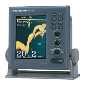
Furuno FCV-1500 User manual

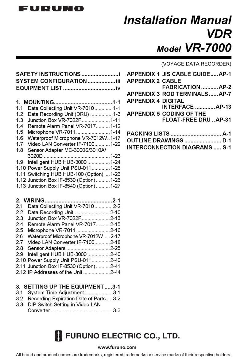
Installation Manual
COLOR VIDEO SOUNDER FCV-1500
COLOR VIDEO MONITOR FCV-1500M
SAFETY INSTRUCTIONS ......................................................i
SYSTEM CONFIGURATION ................................................ii
EQUIPMENT LISTS................................................................. iii
MOUNTING
1.1 Display Unit..........................................................................1
1.2 Transducer (FCV-1500 only)................................................2
1.3 Optional Water Temperature Sensors..................................2
WIRING
2.1 General Wiring.....................................................................4
2.2 Connection of Optional Equipment......................................6
2.3 I/O Data Sentences ...........................................................11
ADJUSTMENTS
3.1 System Menu.....................................................................12
3.2 Transducer Setting (FCV-1500 only) .................................13
3.3 Adjustment for Transmitter Unit/Telesounder/
Picture Recorder................................................................16
3.4 Nav Data Setting................................................................19
3.5 Picture Adjustment.............................................................20
3.6 DIP Switch Settings for EXIF Board ..................................21
APPENDIX........................................................... AP-1
PACKING LISTS.................................................................... A-1
OUTLINE DRAWING ...........................................................D-1
INTERCONNECTION DIAGRAM................................... S-1
Back

Your Local Agent/DealerYour Local Agent/Dealer
9-52 Ashihara-cho,9-52 Ashihara-cho,
Nishinomi
y
a, Ja
p
anNishinomi
y
a, Ja
p
an
Tele
p
hone :Tele
p
hone : 0798-65-21110798-65-2111
fa
x
fa
x
0798-65-42000798-65-4200
::
F
IRST EDITION :
F
IRST EDITION : APR.APR. 19991999
Printed in JapanPrinted in Japan
A
ll ri
g
hts reserved.
A
ll ri
g
hts reserved. K1K1 :: DEC.DEC. 12,200312,2003
PUB.No.PUB.No. IME-23630-K1IME-23630-K1
*00080867401**00080867401*
*00080867401**00080867401*
(( DAMIDAMI )) FCV-1500/MFCV-1500/M * 0 0 0 8 0 8 6 7 4 0 1 ** 0 0 0 8 0 8 6 7 4 0 1 *
*IME23630K10**IME23630K10*
* I M E 2 3 6 3 0 K 1 0 ** I M E 2 3 6 3 0 K 1 0 *

iiiiiiiiiiiii
i
SAFETY INSTRUCTIONS
WARNING
Turn off the power at the switchboard
before beginning the installation.
Fire or electrical shock can result if the
power is left on.
Do not install the equipment where it
may get wet from rain or water splash.
Water in the equipment can result in fire,
electrical shock or equipment damage.
Be sure no water leaks in at the trans-
ducer mounting location.
Water leakage can sink the vessel. Also
confirm that the transducer will not loosen
by ship’s vibration. The installer of the
equipment is solely responsible for the
proper installation of the equipment.
FURUNO will assume no responsibility for
any damage associated with improper
installation.
Be sure that the power supply is
compatible with the voltage rating of
the equipment.
Connection of an incorrect power supply
can cause fire or equipment damage. The
voltage rating of the equipment appears
on the label above the power connector.
ELECTRICAL SHOCK HAZARD
Do not open the equipment
unless totally familiar with
electrical circuits and
service manual.
Only qualified personnel
should work inside the
equipment.
CAUTION
Observe the following compass safe
distances to prevent deviation of a
magnetic compass:
Ground the equipment to
prevent mutual interference.
Display
unit
Standard Steering
compass compass
1.1 m 0.8 m
When handling the transducer cable,
keep in mind following points.
• Keep the cable away from oil and
fuel.
• Keep the cable away from the
place where it may be damaged
during the installation.
• Do not paint the cable.
The sheath of the transducer cable is
made of chlorophrene rubber (or vinyl
chloride). Therefore, do not paint the
sheath with organic liquid (such as
toluene) since it may harm the sheath.

ii
SYSTEM CONFIGURATION
Display Unit
CV-1500/1500M
Transducer*1
Ship's Mains
24/32 VDC
External
Monitor
Water Temperature Sensor
Rectifier
RU-1746B-2
AC100/110/115/200/
220/230V, 1φ, 50/60Hz
Navigator
Sonar, telesounder (TS-50/80)*3,
net recoder
Color Monitor
Interface
OP02-76
(Internal)
Transducer*1
Interface
VI-1100A
Transmitter unit (ETR-2D etc.)
High resolution transceiver unit (IS-73)
Telesounder (TS-7000)*3
Transmitter unit (ETR-2D etc.)
High resolution transceiver unit (IS-73)
Telesounder (TS-7000)*3
Switch Box
EX-7 Same as above.
Same as above.
Same as above. *2
Picture recorder (MT-12)
: FCV-1500 only
: FCV-1500M, FCV-1500 with the
EXIF Board assy (option) only
: Master ship; FCV-1500M, FCV-1500
with the EXIF Board assy are available.
Sister ship; FCV-1500 with the EXIF
Board Assy (option) only.
One external unit is connectable on
the sister ship.
Output signal is one frequency only.
: Option
: Connectable External
Equipment
*1
*2
*3

iii
EQUIPMENT LISTS
Standard Supply
emaNepyTytQ.oNedoCskrameR
tinUyalpsiD 0051-VC 1–0051-VCFroF
M0051-VC–M0051-VCFroF
recudsnarT ,recudsnartWk3ro2,1morftceleS ehtdnavxotviegapotgnirrefer .xidneppA sirecudsnartfiyrasecentonnoitceleS .dellatsniydaerla
0 only051-VCF
epiPlluh-urhT
knaTrecudsnarT
straPerapS10040-20PStes1039-693-100esuF
noitallatsnI slairetaM 10260-20PC tes1 049-693-1000051-VCFroF
20260-20PC090-993-100M0051-VCFroF
seirosseccA00940-20PFtes1573-210-000retliF
Optional Equipment
emaNepyT.oNedoCskrameR
rotinoMroloC ecafretnI 67-20PO773-210-000 ,rotcennocHX,.yssaFIMCsedulcnI pmalc,wercs01X3M
erutarepmeTretaW rosneS
BSM20-T040-040-000epytlluh-urhT
BTM20-T620-040-000elbacm8htiw,tnuommosnarT
BSM30-T720-040-000elbacm8htiw,epytlluh-urhT
reifitceR2-B6471-UR934-030-000CA→CD
.yssAelbaC
FPS6A-JM 050-2100 424-431-000 fonoitcennocrof,m5,P6-P6 rotagivan
FPS6A-JM 001-2100 718-331-000 fonoitcennocrof,m01,P6-P6 rotagivan
FPS6A-JM 050-1100 442-231-000 fonoitcennocrof,m5,P4-P6 rotagivan
FPS6A-JM 001-1100 633-231-000 fonoitcennocrof,m01,P4-P6 rotagivan
revoClyniV1060-620-0140-991-008-000
dooH01620-20PF082-700-200
eriWlyniVkcalB,QS0.2VIK615-455-000htraeroF
rotcennoC P-452-SCN505-605-000 recudsnartfonoitcennocroF )ylno0051-VCF(
P8-41MF804-115-00081-ZNFroF
eldnaH07-30PO024-324-800
tinUrettimsnarT
D2-RTE845-100-000
ylnoM0051-VCF
D3-RTE945-100-000
D5-RTE875-100-000
D01-RTE975-100-000
noituloseRhgiH tinUreviecsnarT 37-SI341-000-000
ecafretnIA0011-IV508-120-000
xoBhctiwS 7-XE 355-720-000
.yssAelbaC -DA552SCN 005L-P452 815-241-000 ycneuqerflaud,0051-VCFroF .noitallatsnirecudsnart
yssadraoBFIXE 77-20PO 873-210-000ylno0051-VCFroF
xoBretsooB 5-TB -ylno0051-VCFroF

iv
Transducers (FCV-1500 only)
1 kW Transducer
ycneuqerF )zHk( lluH lairetaM recudsnarT lluH-urhT epiP knaT
54/51 leetS S4-F51 H3-F54
PRF
05/51
leetS S4-F51 B6/6-B05
PRF
leetS S4-F51 B9-B05
PRF
leetS S4-F51 G8-F05
PRF
86/51 leetS S4-F51 H8-F86
PRF
88/51 leetS S4-F51 8-B88
PRF
002/51 leetS S4-F51 S5-B002
PRF
54/82 leetS 8-F82 H3-F54
PRF
05/82
leetS 8-F82 B6/6-B05
PRF
leetS 8-F82 B9-B05 )2(0006-BWT656-T
PRF
leetS 8-F82 G8-F05
PRF
86/82 leetS 8-F82 H8-F86
PRF
88/82 leetS 8-F82 8-B88 )2(0006-BWT756-T
PRF
002/82 leetS 8-F82 S5-B002
PRF
88/54 leetS H3-F54 8-B88
PRF

v
1 kW Transducer (con’t.)
ycneuqerF )zHk( lluH lairetaM recudsnarT lluH-urhT epiP knaT
002/54 leetS H3-F54 S5-B002
PRF
88/05
leetS B6/6-B05 8-B88
PRF
leetS B9-B05 8-B88 )2(0006-BWT856-T
PRF
leetS G8-F05 8-B88
PRF
002/05
leetS B6/6-B05 S5-B002
PRF
leetS B9-B05 S5-B002
PRF
leetS G8-F05 S5-B002
PRF
leetS T1-002/05
PRF
leetS TS1-002/05
PRF
004/05
leetS B6/6-B05 25-B004
PRF
leetS B9-B05 25-B004
PRF
leetS G8-F05 25-B004
PRF
002/86 leetS H8-F86 S5-B002
PRF
002/88 leetS 8-B88 S5-B002
PRF

vi
2 kW Transducer
ycneuqerF )zHk( lluH lairetaM recudsnarT lluH-urhT epiP knaT
54/51 leetS 01-F51 H6-F54
PRF
05/51 leetS 01-F51 21-B05 )2(0007-BFT726-T
PRF
86/51 leetS 01-F51 H03-F86
PRF
88/51 leetS 01-F51 01-B88 )2(0007-BFT926-T
PRF)2(0011-BRTF-926-T
002/51 leetS 01-F51 N8/B8/8-B002 )2(0007-BFT236-T
PRF)2(0011-BRTF-236-T
54/82 leetS 81-F82 H6-F54
PRF
05/82 leetS 81-F82 21-B05 )2(0007-BFT436-T
PRF
86/82 leetS 81-F82 H03-F86
PRF)2(0011-BRTF-436-T
88/82 leetS 81-F82 01-B88 )2(0007-BFT636-T
PRF)2(0011-BRTF-636-T
002/82 leetS 81-F82 N8/B8/8-B002 )2(0007-BFT836-T
PRF)2(0011-BRTF-836-T
88/54 leetS H6-F54 01-B88
PRF
002/54 leetS H6-F54 N8/B8/8-B002
PRF
88/05 leetS 21-B05 01-B88 )2(0007-BFT346-T
PRF)2(0011-BRTF-346-T
002/05 leetS 21-B05 N8/B8/8-B002 )2(0007-BFT546-T
PRF
002/86 leetS H03-F86 N8/B8/8-B002
PRF)2(0011-BRTF-546-T
002/88 leetS 01-B88 N8/B8/8-B002 )2(0007-BFT946-T
PRF)2(0011-BRTF-946-T

vii
3 kW Transducer
ycneuqerF )zHk( lluH lairetaM recudsnarT lluH-urhT epiP knaT
54/51 leetS 2X01-F51 H21-F54
PRF
05/51 leetS 2X01-F51 H42-F05
PRF
86/51 leetS 2X01-F51 H03-F86
PRF
88/51 leetS 2X01-F51 H621-F88
PRF
701/51 leetS 2X01-F51 R01-B001
PRF
051/51 leetS 2X01-F51 H21-B051
PRF
002/51 leetS 2X01-F51 H21-B002
PRF
54/82 leetS H42-F82 H21-F54
PRF
05/82 leetS H42-F82 H42-F05 )2(0007-BFT186-T
PRF)2(0011-BRTF-186-T
86/82 leetS H42-F82 H03-F86
PRF
88/82 leetS H42-F82 H621-F88 )2(0007-BFT286-T
PRF)2(0011-BRTF-286-T
701/82 leetS H42-F82 R01-B001
PRF
051/82 leetS H42-F82 H21-B051 )2(0007-BFT386-T
PRF)2(0011-BRTF-386-T
002/82 leetS H42-F82 H21-B002 )2(0007-BFT386-T
PRF)2(0011-BRTF-386-T
88/54 leetS H21-F54 H621-F88
PRF
701/54 leetS H21-F54 R01-B001
PRF
051/54 leetS H21-F54 H21-B051
PRF

viii
3 kW Transducer (con’t.)
ycneuqerF )zHk( lluH lairetaM recudsnarT lluH-urhT epiP knaTlluH
002/54 leetS H21-F54 H21-B002
PRF
88/05 leetS H42-F05 H621-F88 )2(0007-BFT286-T
PRF)2(0011-BRTF-286-T
701/05 leetS H42-F05 R01-B001
PRF
051/05 leetS H42-F05 H21-B051 )2(0007-BFT386-T
PRF)2(0011-BRTF-386-T
002/05 leetS H42-F05 H21-B002 )2(0007-BFT386-T
PRF)2(0011-BRTF-386-T
701/86 leetS H03-F86 R01-B001
PRF
051/86 leetS H03-F86 H21-B051 )2(0007-BFT646-T
PRF)2(0011-BRTF-646-T
002/86 leetS H03-F86 H21-B002 )2(0007-BFT646-T
PRF)2(0011-BRTF-646-T
051/88 leetS H621-F88 H21-B051
PRF
002/88 leetS H621-F88 H21-B002 )2(0007-BFT586-T
PRF)2(0011-BRTF-586-T
002/701 leetS R01-B001 H21-B002
PRF

ix
1 kW/2 kW Transducer
tuptuO )W( ycneuqerF )zHk( lluH lairetaM recudsnarT lluh-urhT epiP knaT
k2/k1
54/51 leetS S4-F51 H6-F54
PRF
05/51 leetS S4-F51 21-B05
)2(0007-BFT626-T
PRF)2(0011-BRTF-626-T
86/51 leetS S4-F51 H03-F86
PRF
88/51 leetS S4-F51 01-B88
)2(0006-BWT826-T
PRF)2(0011-BRTF-826-T
002/51 leetS S4-F51 N8/B8/8-B002
)2(0006-BWT136-T
PRF)2(0011-BRTF-136-T
54/82 leetS 8-F82 H6-F54
PRF
05/82 leetS 8-F82 21-B05
PRF
86/82 leetS 8-F82 H03-F86
PRF
88/82 leetS 8-F82 01-B88
PRF
002/82 leetS 8-F82 N8/B8/8-B002
)2(0006-BWT756-T
PRF
88/54 leetS H3-F54 01-B88
PRF
002/54 leetS H3-F54 N8/B8/8-B002
PRF

x
1 kW/2 kW Transducer (con’t.)
tuptuO )W( ycneuqerF )zHk( lluH lairetaM recudsnarT lluh-urhT epiP knaT
k2/k1
88/05
leetS B6/6-B05 01-B88
PRF
leetS B9-B05 01-B88
PRF
leetS G8-F05 01-B88 )2(0007-BFT636-T
PRF)2(0011-BRTF-636-T
002/05
leetS B6/6-B05 N8/B8/8-B002
PRF
leetS 9-B05 N8/B8/8-B002 )2(0006-BWT856-T
PRF
leetS G8-F05 N8/B8/8-B002 )2(0007-BFT836-T
PRF)2(0001-BRTF-836-T
002/86 leetS H8-F86 N8/B8/8-B002
PRF
002/88 leetS 8-B88 N8/B8/8-B002 )2(0006-BWT956-T
PRF

xi
1 kW/3 kW Transducer
tuptuO )W( ycneuqerF )zHk( lluH lairetaM recudsnarT lluH-urhT epiP knaT
k3/k1
54/51 leetS S4-F51 H21-F54
PRF
05/51 leetS S4-F51 H42-F05
PRF
86/51 leetS S4-F51 H03-F86
PRF
88/51 leetS S4-F51 H621-F88
PRF
701/51 leetS S4-F51 R01-B001
PRF
051/51 leetS S4-F51 H21-B051 )2(0007-BFT736-T
PRF)2(0011-BRTF-736-T
002/51 leetS S4-F51 H21-B002
PRF
54/82 leetS 8-F82 H21-F54
PRF
05/82 leetS 8-F82 H42-F05
PRF
86/82 leetS 8-F82 H03-F86
PRF
88/82 leetS 8-F82 H621-F88
PRF
701/82 leetS 8-F82 R01-B001
PRF
051/82 leetS 8-F82 H21-B051
PRF
002/82 leetS 8-F82 H21-B002
PRF
88/54 leetS H3-F54 H621-F88
PRF
701/54 leetS H3-F54 R01-B001
PRF
051/54 leetS H3-F54 H21-B051
PRF

xii
1 kW/3 kW Transducer (con’t.)
tuptuO )W( ycneuqerF )zHk( lluH lairetaM recudsnarT lluH-urhT epiP knaT
k3/k1
002/54 leetS H3-F54 H21-B002
PRF
88/05
leetS B6/6-B05 H621-F88
PRF
leetS B9-B05 H621-F88
PRF
leetS G8-F05 H621-F88
PRF
701/05
leetS B6/6-B05 R01-B001
PRF
leetS B9-B05 R01-B001
PRF
leetS 8-F05 R01-B001
PRF
051/05
leetS B6/6-B05 H21-B051
PRF
leetS B9-B05 H21-B051
PRF
leetS G8-F05 H21-B051
PRF
002/05
leetS B6/6-B05 H21-B002
PRF
leetS B9-B05 H21-B002
PRF
leetS G8-F05 H21-B002
PRF
701/86 leetS H8-F86 R01-B001
PRF
051/86 leetS H8-F86 H21-B051
PRF
002/86 leetS H-F86 H21-B002
PRF
051/88 leetS 8-B88 H21-B051
PRF
002/88 leetS 8-B88 H21-B002
PRF

xiii
2 kW/3 kW Transducer
tuptuO )W( ycneuqerF )zHk( lluH lairetaM recudsnarT lluH-urhT epiP knaT
k3/k2
54/51 leetS 01-F51 H21-F54
PRF
05/51 leetS 01-F51 H42-F05
PRF
86/51 leetS 01-F51 H03-F86
PRF
88/51 leetS 01-F51 H621-F88
PRF
701/51 leetS 01-F51 R01-B001
PRF
051/51 leetS 01-F51 H21-B051
PRF
002/51 leetS 01-F51 H21-B002
PRF
54/82 leetS 81-F82 H21-F54
PRF
05/82 leetS 81-F82 H42-F05
PRF
86/82 leetS 81-F82 H03-F86
PRF
88/82 leetS 81-F82 H621-F88
PRF
701/82 leetS 81-F82 R01-B001 )2(0007-BFT636-T
PRF)2(0011-BRTF-636-T
051/82 leetS 81-F82 H21-B051 )2(0007-BFT736-T
PRF)2(0011-BRTF-736-T
002/82 leetS 81-F82 H21-B002
PRF
88/54 leetS H6-F54 H621-F88
PRF
701/54 leetS H6-F54 R01-B001
PRF
051/54 leetS H6-F54 H21-B051
PRF

xiv
2 kW/3 kW Transducer (con’t.)
tuptuO )W( ycneuqerF )zHk( lluH lairetaM recudsnarT lluH-urhT epiP knaT
k3/k2
002/54 leetS H6-F54 H21-B002
PRF
88/05 leetS 21-B05 H621-F88
PRF
701/05 leetS 21-B05 R01-B001 )2(0007-BFT346-T
PRF)2(0011-BRTF-346-T
051/05 leetS 21-B05 H21-B051 )2(0007-BFT446-T
PRF)2(0011-BRTF-446-T
002/05 leetS 21-B05 H21-B002
PRF
701/86 leetS H03-F86 R01-B001
PRF
051/86 leetS H03-F86 H21-B051
PRF
002/86 leetS H03-F86 H21-B002
PRF
051/88 leetS 01-B88 H21-B051
PRF
002/88 leetS 01-B88 H21-B002
PRF

xv
3 kW/2 kW Transducer
tuptuO )W( ycneuqerF )zHk( lluH lairetaM recudsnarT lluH-urhT epiP knaT
k2/k3
54/51 leetS 2X01-F51 H6-F54
PRF
05/51 leetS 2X01-F51 21-B05
PRF
86/51 leetS 2X01-F51 H03-F86
PRF
88/51 leetS 2X01-F51 01-B88
PRF
002/51 leetS 2X01-F51 N8/B8/8-B002
PRF
54/82 leetS H42-F82 H6-F54
PRF
05/82 leetS H42-F82 21-B05
PRF
86/82 leetS H42-F82 H03-F86
PRF
88/82 leetS H42-F82 01-B88
PRF
002/82 leetS H42-F82 N8/B8/8-B002
PRF
88/54 leetS H21-F54 01-B88
PRF
002/54 leetS H21-F54 N8/B8/8-B002
PRF
88/05 leetS H42-F05 01-B88
PRF
002/05 leetS H42-F05 N8/B8/8-B002
PRF
002/86 leetS H03-F86 N8/B8/8-B002 )2(0007-BFT746-T
PRF)2(0011-BRTF-746-T
002/88 leetS H621-F88 N8-B002
PRF
002/001 leetS R01-B001 N8/B8/8-B002 )2(0007-BFT946-T
PRF)2(0011-BRTF-946-T

1
MOUNTING
1.1 Display Unit
Mounting considerations
The display unit is designed to be mounted on a desktop. When selecting a mounting
location for the display unit keep in mind the following points.
• Locate the unit where it can be easily operated and the screen viewed while looking
over the bow.
• Locate the unit out of direct sunlight and away from heat sources because of heat that
can build up inside the cabinet.
• Locate the equipment away from places subject to water splash and rain.
• Be sure the mounting location is strong enough to support the weight of the unit under
the continued vibration which is normally experienced on the ship. If necessary rein-
force the mounting location.
• Leave sufficient space on the sides and rear of the unit to facilitate maintenance.Also,
leave a foot or so of “service loop” in cables behind the unit so it can be pulled forward
for servicing or easy removal of connectors.
• Amagnetic compass will be affected if placed too close to the display unit. Observe the
following compass safe distances to prevent deviation of a magnetic compass: Stan-
dard compass, 1.1 m, Steering compass, 0.8 m.
Procedure
1. Unfasten two bolts (M8X40) at the front of the display unit. Remove the mounting plate.
2. Referring to the drawing below for dimensions, drill four mounting holes of ø12 mm in
the mounting location.
200
26 26
100
160
490
20072
100
400
100
4-φ12
All dimensions
in millimeters
Figure 1-1 Display unit mounting dimensions
3. Fix the mounting plate to the mounting location with M10 bolts, nuts and washers.
4. Fasten the display unit to the mounting plate with the screws removed at step 1.

2
1.2 Transducer (FCV-1500 only)
The performance of the color video sounder greatly depends on the transducer location.A
place least affected by air bubbles should be selected since turbulence interferes with
sounding. Also, select a place least influenced by engine noise. It is known that bubbles
are at a minimum, at normal cruising speed, at the location where the first bow wave falls
and the next wave rises. On small, low speed boats, the position between 1/3 and 1/2 of
ship’s length from the bow is usually a good place. The face of the transducer must be
facing the sea bottom in normal cruising trim of the ship.
1.3 Optional Water Temperature Sensors
Transom mount water temperature sensor T-02MTB
Select a suitable mounting location considering the following:
• Fix the cable at a convenient location with a cable clamp.
• When the cable is to be led in through the transom board, make a hole of approx. 17
mm in diameter to pass the connector.After passing the cable through the hole, fill the
hole with a suitable sealing compound.
D>50 cm D
Tapping
Screw
(M5X20)
Mount sensor flush
with hull bottom.
Figure 1-2 How to install transom mount water temperature sensor T-02MTB

3
Thru-hull mount water temperature sensor T-02MSB, T-03MSB
When selecting a mounting location for the sensor keep in mind the following points:
• Select a mid-boat flat position.
• The sensor does not have to be installed perfectly perpendicular, however it must not
be located where it won’t be damaged when the boat is dry docked.
• Select a place apart from equipment generating heat.
• Select a place in the forward direction viewing from the drain hole, to allow for circula-
tion of cooling water.
• Select a place free from vibration.
Thickness within
25 mm
Rubber Gasket
Rubber Gasket
Washer
Lock Nut
Apply sealant.
Sensor
Cable
φ21 mm
Lock Nut
Washer
Apply sealant.
Holder Guide
Lock Nut
Sensor Holder
T-02MSB T-03MSB
φ25 mm
1. Drill a hole of φ21 mm in the hull.
2. Pass the sensor cable through the hull.
3. Pass the rubber gasket, washer and lock
nut onto the cable in that order.
4. Apply high-grade sealant to the sensor
flange, sensor and lock nut. Tighten the
lock nut. Do not overtighten it; torque
should be less than 59N•m.
5. Launch the boat and check for water
leakage around the sensor.
1. Drill a hole of φ25 mm in the hull.
2. Coat the holder guide with sealant, and then
pass it through the hull from outside the boat.
3. Pass the rubber gasket, washer and lock nut
onto the holder guide in that order. Tighten the
lock nut. Torque should be less than 59N•m.
4. Lead in the sensor holder from inside the boat
and set it to the holder guide. Tighten the lock
nut.
5. Launch the boat and check for water leakage
around the sensor.
Figure 1-3 How to mount thru-hull mount water temperature sensors T-02MSB, T-03MSB
This manual suits for next models
1
Table of contents
Other Furuno Marine Equipment manuals

Furuno
Furuno FELCOM 12 User manual

Furuno
Furuno Felcom 50 User manual

Furuno
Furuno VR-3000 User manual

Furuno
Furuno FE-700 User manual

Furuno
Furuno GP-39 User manual

Furuno
Furuno TZT2BB User manual
Furuno
Furuno FELCOM251 User manual

Furuno
Furuno FELCOM251 User manual

Furuno
Furuno FW-200 User manual

Furuno
Furuno DS-50 User manual

Furuno
Furuno FICE-100 User manual

Furuno
Furuno NX-700A/B Operators User manual

Furuno
Furuno Sc 50 Manual

Furuno
Furuno DSC-6A User manual

Furuno
Furuno 3D Sonar Visualizer F3D-S User manual

Furuno
Furuno FMD-3200 User manual

Furuno
Furuno ETR-10N User manual

Furuno
Furuno VR-7000 Manual

Furuno
Furuno FA-170 User manual

Furuno
Furuno LS-4100 User manual