manuals.online logo
Brands
  1. Home
  2. •
  3. Brands
  4. •
  5. AXIOMTEK
  6. •
  7. Motherboard
  8. •
  9. AXIOMTEK PICO821 Series User manual

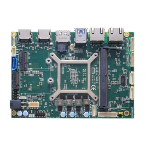
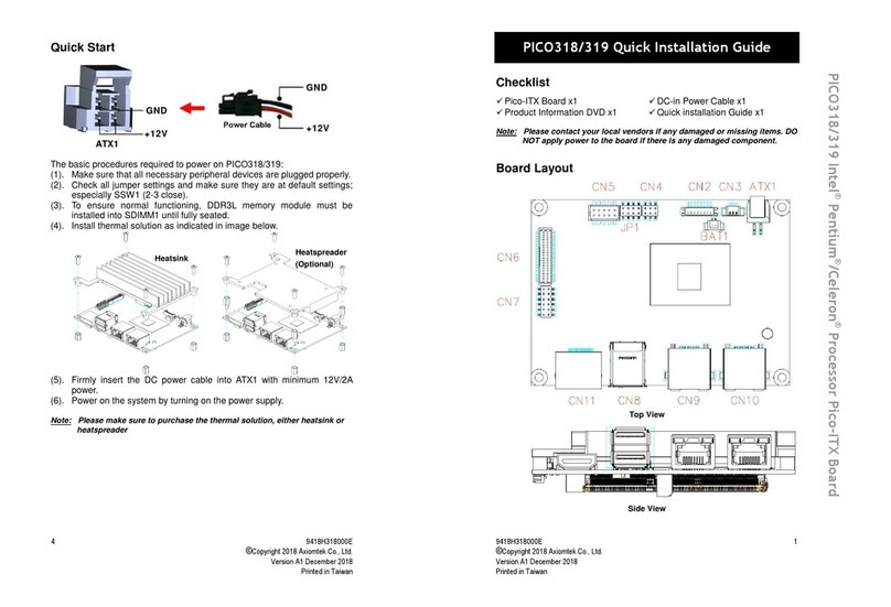
AXIOMTEK PICO821 Series User manual

Other AXIOMTEK Motherboard manuals

AXIOMTEK MANO873 Series User manual

AXIOMTEK

AXIOMTEK MANO873 Series User manual

AXIOMTEK IMB205 Operational manual

AXIOMTEK

AXIOMTEK IMB205 Operational manual

AXIOMTEK MANO526 User manual

AXIOMTEK

AXIOMTEK MANO526 User manual

AXIOMTEK imb500 User manual

AXIOMTEK

AXIOMTEK imb500 User manual

AXIOMTEK SBC81613 User manual

AXIOMTEK

AXIOMTEK SBC81613 User manual

AXIOMTEK SHB211 Series User manual

AXIOMTEK

AXIOMTEK SHB211 Series User manual

AXIOMTEK SHB102 Series User manual

AXIOMTEK

AXIOMTEK SHB102 Series User manual

AXIOMTEK EP850 Series User manual

AXIOMTEK

AXIOMTEK EP850 Series User manual

AXIOMTEK SBC84600 Series User manual

AXIOMTEK

AXIOMTEK SBC84600 Series User manual

AXIOMTEK SBC8163 User manual

AXIOMTEK

AXIOMTEK SBC8163 User manual

AXIOMTEK MANO315 Series User manual

AXIOMTEK

AXIOMTEK MANO315 Series User manual

AXIOMTEK PICO317 User manual

AXIOMTEK

AXIOMTEK PICO317 User manual

AXIOMTEK MANO560 Series User manual

AXIOMTEK

AXIOMTEK MANO560 Series User manual

AXIOMTEK CEM300 User manual

AXIOMTEK

AXIOMTEK CEM300 User manual

AXIOMTEK CEM130 User manual

AXIOMTEK

AXIOMTEK CEM130 User manual

AXIOMTEK SHB103 Series User manual

AXIOMTEK

AXIOMTEK SHB103 Series User manual

AXIOMTEK SHB210 Series User manual

AXIOMTEK

AXIOMTEK SHB210 Series User manual

AXIOMTEK NANO830 User manual

AXIOMTEK

AXIOMTEK NANO830 User manual

AXIOMTEK CAPA312 User manual

AXIOMTEK

AXIOMTEK CAPA312 User manual

AXIOMTEK MANO522 Series User manual

AXIOMTEK

AXIOMTEK MANO522 Series User manual

AXIOMTEK CEM130 User manual

AXIOMTEK

AXIOMTEK CEM130 User manual

AXIOMTEK MANO111 Series User manual

AXIOMTEK

AXIOMTEK MANO111 Series User manual

AXIOMTEK CAPA841 User manual

AXIOMTEK

AXIOMTEK CAPA841 User manual

AXIOMTEK SHB111 User manual

AXIOMTEK

AXIOMTEK SHB111 User manual

Popular Motherboard manuals by other brands

Gigabyte MNJ190I-FH user manual

Gigabyte

Gigabyte MNJ190I-FH user manual

Biostar HI-FI-Z87X-3D Setup manual

Biostar

Biostar HI-FI-Z87X-3D Setup manual

Atmel SAM9753PIA-DK user guide

Atmel

Atmel SAM9753PIA-DK user guide

Coapt GEN2 Handbook

Coapt

Coapt GEN2 Handbook

Supero SUPER P4DL6 user manual

Supero

Supero SUPER P4DL6 user manual

Cypress CY3210-PSoCEVAL1 quick start guide

Cypress

Cypress CY3210-PSoCEVAL1 quick start guide

ASROCK B660M-HDV manual

ASROCK

ASROCK B660M-HDV manual

Fujitsu D2831 Short description

Fujitsu

Fujitsu D2831 Short description

Industrial Computers ADE-6050 user manual

Industrial Computers

Industrial Computers ADE-6050 user manual

Asus TUF Z270 MARK 2 manual

Asus

Asus TUF Z270 MARK 2 manual

DFI NB71-BC user manual

DFI

DFI NB71-BC user manual

ASROCK H61 Pro BTC user manual

ASROCK

ASROCK H61 Pro BTC user manual

Norco POS-7893 user manual

Norco

Norco POS-7893 user manual

Intel DG965MS specification

Intel

Intel DG965MS specification

Asus B85M-VIEW PAKER user manual

Asus

Asus B85M-VIEW PAKER user manual

Asus P5G41T-M LX V2 user manual

Asus

Asus P5G41T-M LX V2 user manual

Gigabyte GA-K8VT800-RH user manual

Gigabyte

Gigabyte GA-K8VT800-RH user manual

Gigabyte Z790M AORUS ELITE user manual

Gigabyte

Gigabyte Z790M AORUS ELITE user manual

manuals.online logo
manuals.online logoBrands
  • About & Mission
  • Contact us
  • Privacy Policy
  • Terms and Conditions

Copyright 2025 Manuals.Online. All Rights Reserved.

PICO821 Series Quick Installation Guide
©Copyright 2009 AXIOMTEK Co., Ltd.
Version A1 September 2009
Printed in Taiwan
9418H821010E
4
V. Board Layout
Component Side
SoldComponent Side
Solder Side
Please refer to the PICO821 Series Product Information CD for the complete User’s Manual, drivers and utilities.
PICO821 Series Quick Installation Guide
©Copyright 2009 AXIOMTEK Co., Ltd.
Version A1 September 2009
Printed in Taiwan
9418H821010E
1
I. Checklist
9PICO821 Pico-ITX Board x 1
9Quick Installation Guide x 1
9Product Information CD x 1
92-pin Jumper Cap, Pitch=2.0mm x 5
9DVI-D kit x 1(Option)
9LAN kit x 1(Option)
9Power Input Cable x 1(Option)
92xUSB Cable x 2(Option)
9USB Client Cable x 1(Option)
9Audio Cable x 1(Option)
9COM + PS/2 Cable x 1(Option)
Note: Please contact your local vendors if any damaged or missing items.
DO NOT apply power to the board if any damaged components.
II. Jumper Settings
Before applying the power to PICO821 Series, please make sure all
jumper settings are defaulted as the following table:
Description Function Jumper Setting
3.3V (Default)
Flat Panel
Connector (CN5)
Voltage Selection :
JP1
5V
Normal (Default)
CMOS Clear : JP2
Clear CMOS
Description Function Jumper Setting
Please refer to the PICO821 Series Product Information CD for the complete User’s Manual, drivers and utilities.
PICO821 Series Quick Installation Guide
©Copyright 2009 AXIOMTEK Co., Ltd.
Version A1 September 2009
Printed in Taiwan
9418H821010E
2
3.3V (Default)
Compact Flash™
Power Select : JP3
5V
ON
AUTO BUTTON
Mode Selection :
JP4
OFF
(Default)
ConnectorsConnectors Label
Inverter Connector CN2
DC Power Connector CN3
LAN Connector CN4
LVDS Connector CN5
SMBUS Connector CN6
USB4&5 Connector CN7
KB/MS Connector CN8
USB0&1 Connector CN9
USB CLIENT Connector CN10
COM Port Connector CN11
DIO Port Connector CN12
Flat Panel Bezel Connector CN13
PATA Connector CN14
AUDIO Connector CN15
DDRII SODIMM Connector SCN1
Compact Flash Connector SCN2
Please refer to the PICO821 Series Product Information CD for the complete User’s Manual, drivers and utilities.
PICO821 Series Quick Installation Guide
©Copyright 2009 AXIOMTEK Co., Ltd.
Version A1 September 2009
Printed in Taiwan
9418H821010E
3
IV. Front Panel Connectors: CN13
Power LED
This 3-pin connector denoted as Pin 1 and Pin 5 connects the system
power LED indicator to such a switch on the case. Pin 1 is assigned as
+, and Pin 5 as -. The Power LED lights up when the system is powered
ON.
External Speaker and Internal Buzzer Connector
Pin 2, 4, 6 and 8 can be connected to the case-mounted speaker unit or
internal buzzer. While connecting the CPU card to an internal buzzer,
please short pins 2-4; while connecting to an external speaker, you
need to set pins 2-4 to Open and connect the speaker cable to pin 8 (+)
and pin 2 (-).
ATX Power On/Off Button
This 2-pin connector denoted as Pin 9 and 10 connects the front panel’s
ATX power button to the CPU card, which allows users to control ATX
power supply to be power on/off.
System Reset Switch
Pin 11 and 12 can be connected to the case-mounted reset switch that
reboots your computer instead of turning OFF the power switch. It is a
better way to reboot your system for a longer life of the system’s power
supply.
HDD Activity LED
This connection is linked to hard drive activity LED on the control panel.
LED flashes when HDD is being accessed. Pin 13 and 14 connect the
hard disk drive to the front panel HDD LED, Pin 13 assigned as -, and
Pin 14 as +.
Please refer to the PICO821 Series Product Information CD for the complete User’s Manual, drivers and utilities.