PESDU1M02 (MID)
5
Remark: 1. LED indication begins when the button is pushed down.
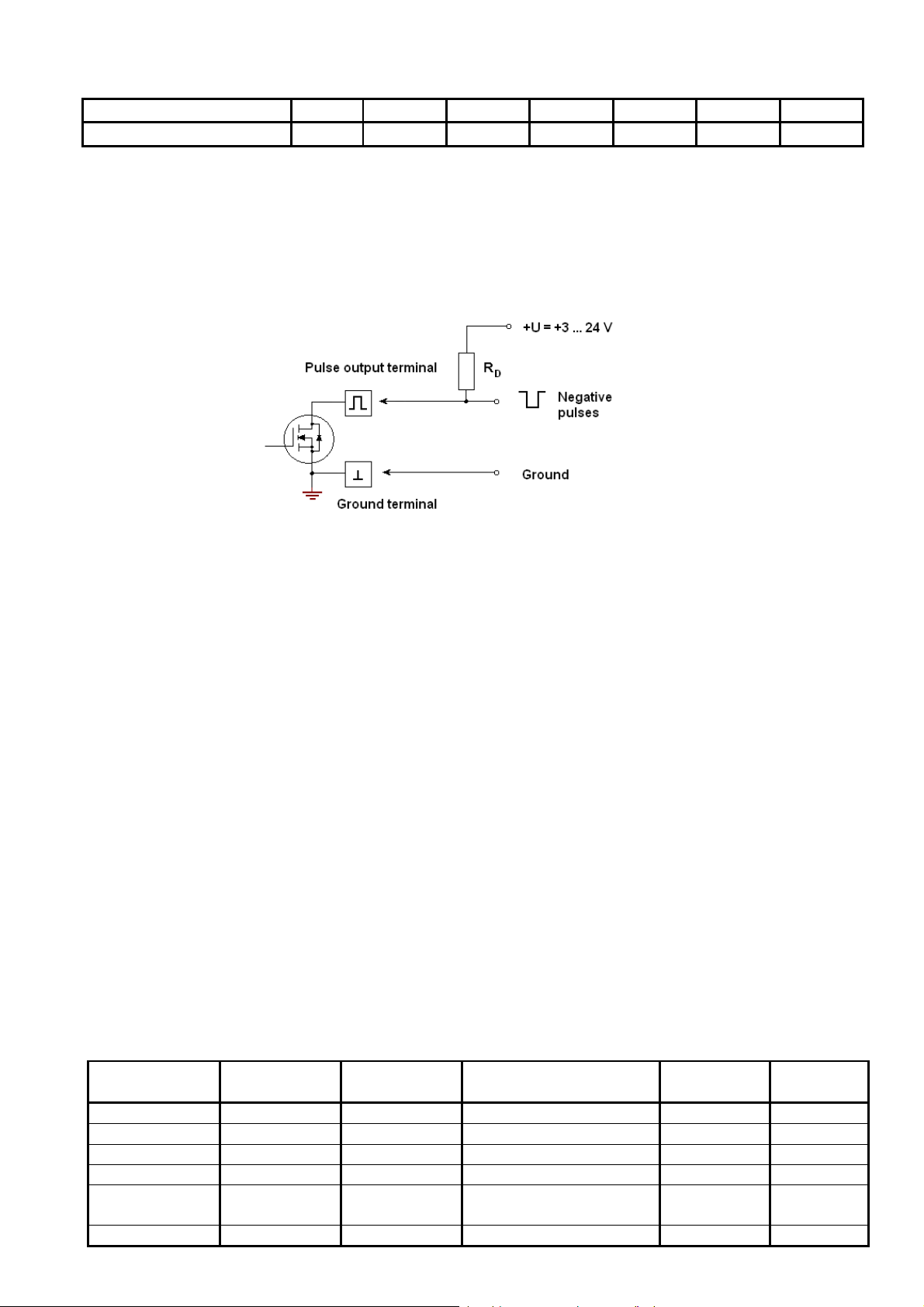
Status signals E (Error) and D (Direction) are passive signals and should be wired using the open drain
output signal connection diagram such shown in 2.6.1 p.
2.8. When the measured flow rate exceeds maximal flow q
s
per +10 %, the flow sensor transmits
the amount of pulses which corresponds to the flow rate q
s
+10 % and indicates corresponding
overflow status code.
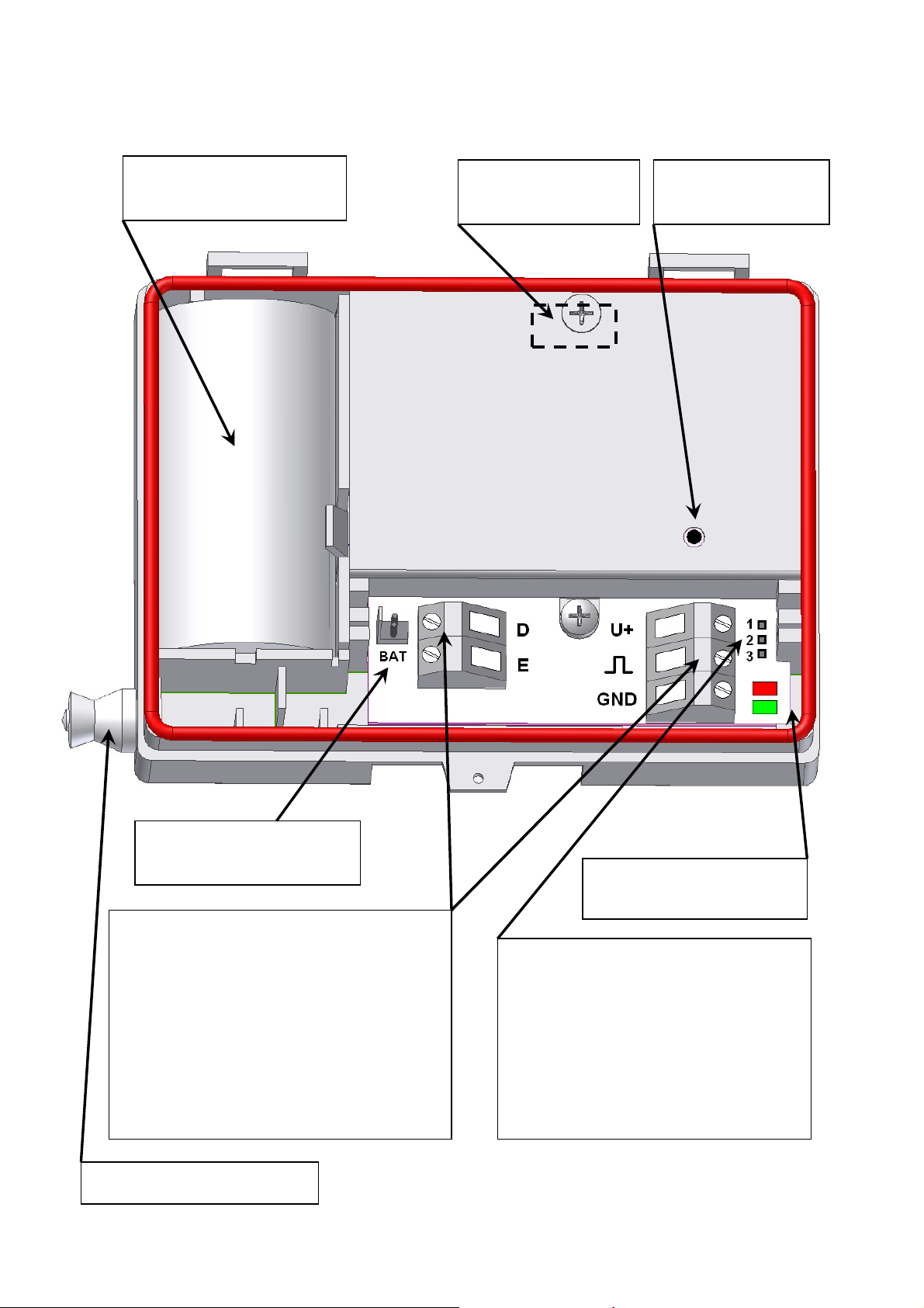
2.9. The flow sensor is powered:
- From an external power source DC 3,6V ±0,2V (average current less than 35 µA),
or
- From internal +3.6V lithium battery, size C, with up to 12 years lifetime.
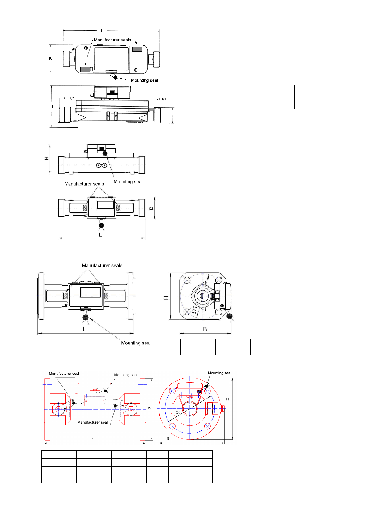
2.10. Table of flow sensor weight, corresponding with the nominal diameter:
Permanent flow q
p
, m3/h 3,5 6 10 15 25 40 60
Weight, less than, kg 3,0 3,0 3,2 6,0 10,5 13,5 14
Dimensions of the flows sensors and its connection flanges is presented in the A appendix.
2.11. Environmental conditions:
- ambient temperature 5
o
C to 55
o
C,
- ambient humidity < 93 %,
- atmospheric pressure 86 kPa to 106,7 kPa,
- fluid temperature 10
o
C to 130
o
C,
- fluid pressure <1,6 MPa.
2.12. Degree of protection IP65 or IP67 (with separate order)
2.13. The flow sensor meets the requirements according to 89/336/EEC, EN50082-2, EN50081-2
3. PACKAGE CONTENT
Components included in the complete Quantity Remark
1. Flow sensor SDU-1 1
2. Set of additional connection flanges 1 *
3. Technical description, operating instruction of SDU-1 1
4. Pulse cable (length from 3 m to 200 m) 1 **
5. 3,6V lithium battery, 8Ah, size C 1 *
REMARK: * - included on demand only
** - cable length depending on the order. Standard length – 3 m.
4. OPERATING PRINCIPLE
4.1. The ultrasonic flowmeter SDU-1 is microcontroller based device that consists of flow sensor
and electronic part mounted on the flow sensor.
Flow measurement is based on the time-of flight measurement method. Fluid volume is
calculated according the formula:
V =K
H
* K
M
* (1/t
+
- 1/t
-
) *T ,
where: V - measured fluid volume, m
3
;
T – time of integration, s;
t
+
- measured upstream time of flight of ultrasonic pulse, s;
t
-
- measured downstream time of flight of ultrasonic pulse, s;
K
H
– hydrodynamic correction factor;
K
M
–coefficient that depends on the flow sensor dimensions.
Measured flow rate is converted into the pulses quantity that is transferred in output pulse terminal.