M&C EC Series User manual

Ultra Low Gas Cooler Series EC®
EC30 and EC-30/FD
Instruction Manual
Version 1.01.00

2 EC-30 | 1.01.00 www.mc-techgroup.com
Content
1General information................................................................................................................5
2Declaration of conformity....................................................................................................... 5
3Safety instructions.................................................................................................................. 6
4Warranty ..................................................................................................................................6
5Used terms and signal indications.........................................................................................7
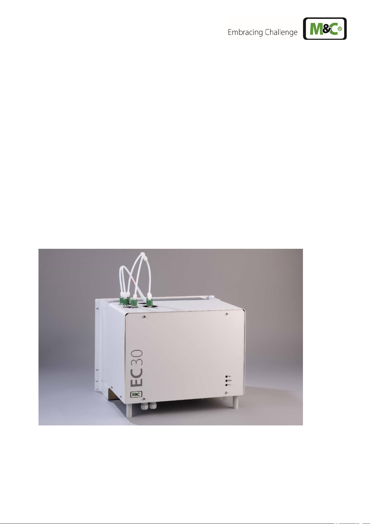
6Introduction............................................................................................................................. 8
6.1 Serial number........................................................................................................................8
7Application............................................................................................................................... 9
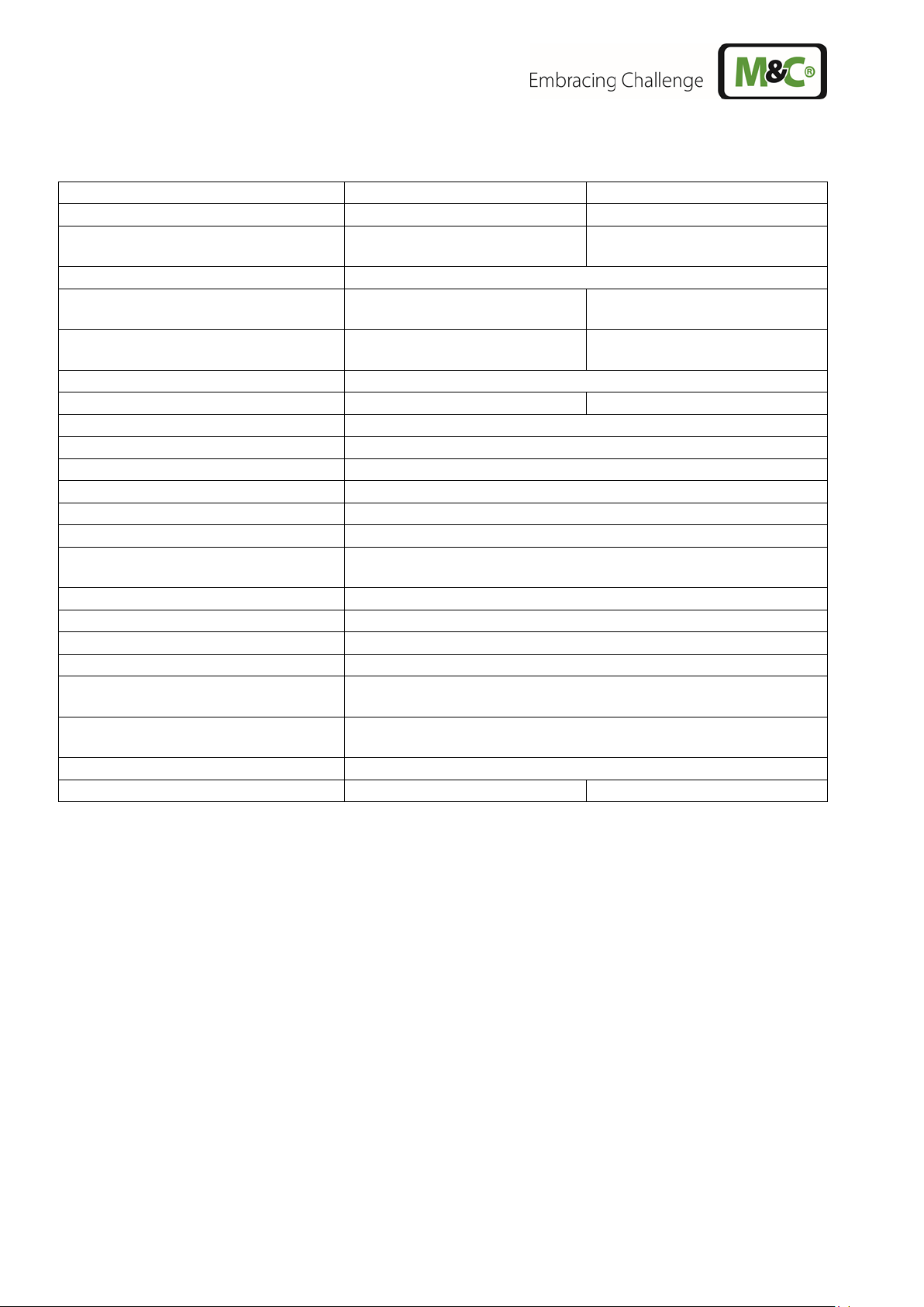
8Technical data....................................................................................................................... 10
9Description ............................................................................................................................ 10
9.1 Assembly............................................................................................................................. 11
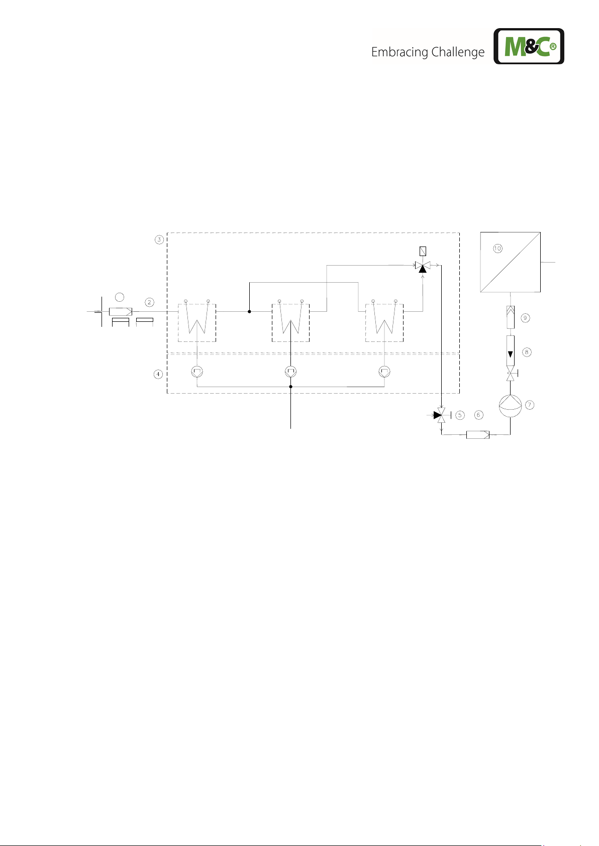
10 Function................................................................................................................................. 12
11 Reception and storage.......................................................................................................... 14
12 Installation instructions........................................................................................................ 15
13 Supply connections.............................................................................................................. 15
13.1 Hose connections................................................................................................................ 15
13.2 Electrical connections.......................................................................................................... 16
14 Start-up.................................................................................................................................. 18
14.1 Function sequence and LED function display...................................................................... 18
15 Closing down......................................................................................................................... 20
16 Maintenance .......................................................................................................................... 20
16.1 Maintenance of the peristaltic pumps type SR25.1 of the EC-30/FD.................................... 21
16.1.1 Change of the pump tube...............................................................................................21
16.1.2 Change of contact pulleys and springs........................................................................... 22
16.1.3 Cleaning the pump head................................................................................................22
16.2 Replacing the heat exchangers ...........................................................................................23
17 Trouble shooting................................................................................................................... 24
18 EC automatic control board.................................................................................................. 26
18.1 Connecting the cooling compressor..................................................................................... 27
18.2 Temperature setting for the cooler....................................................................................... 28
19 temperature sensors............................................................................................................. 28
19.1 Checking the temperature sensor of the pre-cooling stage.................................................. 28
19.2 Checking the temperature sensor of the deep cooling stage................................................29
20 EC control board................................................................................................................... 31
20.1 Function sequence of the EC30 control electronics ............................................................. 32
21 Spare parts list ...................................................................................................................... 34
22 Appendix................................................................................................................................ 35

www.mc-techgroup.com EC-30 | 1.01.00 3
List of Illustrations
Figure 1 Example of application of EC-30/FD................................................................................ 9
Figure 2 EC-30 with options EC-F and EC-FD.............................................................................11
Figure 3 Schematic diagram of functioning of heat exchanger.....................................................12
Figure 4 Tubing of the heat exchangers.......................................................................................13
Figure 5 Timing schematic of the switching processes.................................................................13
Figure 6 Position of terminal X0...................................................................................................17
Figure 7 Electrical connections ....................................................................................................17
Figure 8 Change of the pump tube...............................................................................................21
Figure 9 EC automatic control board............................................................................................26
Figure 10 Connection diagram for compressor ..............................................................................27
Figure 11 Temperature adjustment................................................................................................28
Figure 12 Voltage in relation to the temperature of the cooling stage.............................................29
Figure 13 Resistance-temperature characteristics of the PT100 temperature sensor.....................29
Figure 14 Sensor voltage as function of temperature.....................................................................30
Figure 15 EC30 control board........................................................................................................31
Figure 17 Sample outlet dew point.................................................................................................36
Figure 18 Circuit diagram EC automatic control board...................................................................37
Figure 19 Circuit Diagram EC-30...................................................................................................38
Figure 20 Circuit diagram control electronic EC-30........................................................................39
Figure 21 Wiring plan automatic condensate removal unit EC-FD..................................................40

4 EC-30 | 1.01.00 www.mc-techgroup.com
Dear customer,
we have made up this operating manual in such a way that all necessary information about the product
can be found and understood quickly and easily.
Should you still have any question, please do not hesitate to contact M&C directly or go through your
appointed dealer. Respective contact addresses are to be found in the annexe to this operating manual.
Please also contact our homepage www.mc-techgroup.com forfurther information about our products.
There, you can read or download the data sheets and operating manuals of all M&C products as well
as further information in German and English.
This Operating Manual does not claim completeness and may be subject
to technical modifications.
© 01/2017 M&C TechGroup Germany GmbH. Reproduction of this
document or its content is not allowed without permission from M&C.
Version: 1.01.00

www.mc-techgroup.com EC-30 | 1.01.00 5
Head Office
M&C TechGroup Germany GmbH Rehhecke 79 40885 Ratingen Germany
Telephone: 02102 / 935 - 0
Fax: 02102 / 935 - 111
E - mail: [email protected]
www.mc-techgroup.com
1 GENERAL INFORMATION
The product described in this operating manual has been examined before delivery and left our works
in perfect condition related to safety regulations. In order to keep this condition and to guarantee a safe
operation, it is important to heed the notes and prescriptions made in this operating manual.
Furthermore, attention must be paid to appropriate transportation, correct storage, as well as
professional installation and maintenance work.
All necessary information a skilled staff will need for appropriate use of this product are given in this
operating manual.
2 DECLARATION OF CONFORMITY
CE - Certification
The product described in this operating manual complies with the following EU directives:
EMV-Instruction
The requirements of the EU directive 2014/30/EU “Electromagnetic compatibility“ are met.
Low Voltage Directive
The requirement of the EU directive 2014/35/EU “Low Voltage Directive“ are met.
The compliance with this EU directive has been examined according to DIN EN 61010.
Declaration of conformity
The EU Declaration of conformity can be downloaded from the M&C homepage or directly requested
from M&C.

6 EC-30 | 1.01.00 www.mc-techgroup.com
3 SAFETY INSTRUCTIONS
Please take care of the following basic safety procedures when mounting, starting up or
operating this equipment:
Read this operating manual before starting up and use of the equipment. The information and warnings
given in this operating manual must be heeded.
Any work on electrical equipment is only to be carried out by trained specialists as per the regulations
currently in force.
Attention must be paid to the requirements of VDE 0100 (IEC 364) when setting high-power electrical
units with nominal voltages of up to 1000 V, together with the associated standards and stipulations.
Check the details on the type plate to ensure that the equipment is connected to the correct mains
voltage.
Protection against touching dangerously high electrical voltages:
Before opening the equipment, it must be switched off and hold no voltages. This also applies to any
external control circuits that are connected.
The device is only to be used within the permitted range of temperatures and pressures.
Check that the location is weather-protected. It should not be subject to either direct rain or moisture.
The device must not be used in hazardous areas.
Installation, maintenance, monitoring and any repairs may only be done by authorized personnel with
respect to the relevant stipulations.
4 WARRANTY
If the equipment fails, please contact M&C directly or else go through your M&C authorised dealer.
We offer a one year warranty as of the day of delivery as per our normal terms and conditions of sale,
and assuming technically correct operation of the unit. Consumables are hereby excluded. The terms
of the warranty cover repair at the factory at no cost or the replacement at no cost of the equipment
free ex user location. Reshipments must be send in a sufficient and proper protective packaging.

www.mc-techgroup.com EC-30 | 1.01.00 7
5 USED TERMS AND SIGNAL INDICATIONS
DANGER!
This means that death, severe physical injuries and/or important
material damages will occur in case the respective safety measures
are not fulfilled.
WARNI NG!
This means that death, severe physical injuries and/or important
material damages may occur in case the respective safety measures
are not fulfilled.
CARE!
This means that minor physical injuries may occur in case the
respective safety measures are not fulfilled.
CARE!
Without the warning triangle meansthat a material damage may occur
in case the respective safety measures are not met.
ATTENTION!
This means that an unintentional situation or an unintentional status
may occur in case the respective note is not respected.
NOTE!
These are important information about the product or parts of the
operating manual which require user’s attention.
SKILLED STAFF
These are persons with necessary qualification who are familiar with
installation, use and maintenance of the product.

8 EC-30 | 1.01.00 www.mc-techgroup.com
6 INTRODUCTION
The patented M&C EC30 gas cooler with universal unit EC-F and EC-30/FD with unit EC-FD is always
to be installed in situations where there is interference from moisture in the gas to be measured, or if
the measured components exhibit very high sensitivity to water vapour or if long and expensive heated
sampling lines are to be avoided.
Reduction of the gas temperature inside the cooler to a stable and very low dew point effects a
condensing out of the sample gas. Dry gas leaves the gas cooler and passes into the analyser after
suitable filtration. When installing the EC30(/FD) gas cooler on site in a frost-free protective housing,
there is no need to use a heated sample line with a high energy consumption as long as the ambient
temperature does not fall below a value of -25C.
6.1 SERIAL NUMBER
The type plate with the serial number is located at the side panel of the cooler housing (19“ version).
Whenever you call M&C regarding questions or orders for the spares please give us the serial number
of your EC30.

www.mc-techgroup.com EC-30 | 1.01.00 9
7 APPLICATION
The patented M&C ultra-low temperature cooler EC-30(/FD) finds its applications in the analytical field
for reducing the dew point of humid sample gases, providing a stable and very low dew point and
reducing aerosol formation in the analyser. By mounting the cooler near to the sample point, costly
energy consuming heated sample lines can be avoided. An extremely stable and low gas dew point
avoids water vapour cross-sensitivity and volumetric errors.
Figure 1 shows a typical example of an application for installation of an EC-30 gas cooler unit.
Filter sample probe SP... Universal unit EC-FD Membrane pump Analyser
Heated sample line 3-way-ball valve Flow meter FM
EC-30/FD cooler Super-fine filter FP... Aerosol filter CLF
Deep cooling stage 1 Deep cooling stage 2 Pre cooling stage
Figure 1 Example of application of EC-30/FD
The gas to be measured is taken from the EC-30/FD gas cooler by a gas sample probe and cooled
down to a dew point of -30°C. Via the universal unit EC-FD the condensate is removed. The super-
fine filter located afterwards removes solid particles. For increased operating safety of the entire
system we recommend installing a super-fine filter with a liquid alarm sensor. If required an aerosol
filter can be installed in front of the flow meter . The gas thus treated can now be passed into the
analyser . Via the 3-way-ball valve it is possible to feed test gas for calibration to the analyser.
1
EC-FD
Sample gas IN
Sample
gas OUT
EC-30
Condensate
OUT
Test gas
IN

10 EC-30 | 1.01.00 www.mc-techgroup.com
8 TECHNICAL DATA
Cooler series EC®
Version EC-30
Version EC-30/FD
Part No.
02K6000 (a)**
02K6010 (a)**
With integrated universal unit:
EC-F to force the ventilation
EC-FD ventilation and
condensate removal
Gas connection
tube connector DN 4/6 i./o. d. mm
Condensate connections
3x tube connector GL25-12 mm
1x tube connector DN 4/6 i./o. d.
mm
Material of sample contacting parts
Duran glass, PTFE, PVDF
Duran glass, PTFE, PVDF,
Novoprene
Single stream, gas flow rate
90 Nl/hr-250 Nl/hr*
Gas pressure
max. 3 bar abs.
max. 2 bar abs.
Ambient temperature
+5 to +45 °C
Storage temperature
-20 to +60°C
Sample outlet dew point
-30 °C
Sample inlet temperature
max. 180 °C*
Sample inlet dew point
max. 80 °C*
Cooling capacity at 25 °C ambient
max. 860 kJ/hr*
Main power connection / Power
consumption
230V 50Hz 380VA or **Part No. ...-a = 115V 60 Hz 380VA
Start up time
< 60 min.
Stagnant space
approx.160 ml
ΔP at 250 Nl/hr flow rate
5 mbar
Electrical connection
2,5 mm2terminals, 2x PG13,5 cable glands
Status alarm
2 changeover contacts, potential free contact rating 250V, 3A,
500VA, 50W
Case protection / Electrical equipment
standard
IP20 EN 60529 / EN 61010
Method of mounting / Case colour
19" rack or wall / case colour RAL 9003
Dimension / Weight
84 TE x 8 HE x 360 mm / 37 kg
84 TE x 10 HE x 360 mm / 42 kg
* Maximum values in technical datas must be rated in consideration of total cooling capacity at 25 °C ambient temperature and an outlet
dew point of -30 °C.
9 DESCRIPTION
The patented M&C gas cooler EC-30(/FD) is a two stage combination of compressor and Peltier cooler
with status alarm and automatic defrosting of the dual deep freezer unit for 100% sample availability.
The pre-cooler of the gas cooler EC- is fitted with a “Jet-Stream“ heat exchanger EC-G which is
cooled by a compressor cooling unit with electronic control at a constant temperature of +1°C. Optimum
cooling of sample gases and pre-elemination of a larger part of the condensate from the gas is reliably
achieved. No external pre-draining is normally needed. The deep freezer and is cooled with two
modified “Jet-Stream“ heat exchangers EC-30 fitted between two automatic cooling units for a minimum
temperature of -30 °C. The special design of the Jet-Stream heat exchanger guarantees optimum dew
point reduction to a low, stable value and secures condensate separation. The gas outlets of the heat
exchangers are connected to a 3/2 way solenoid valve. An electronic control system EC-30 switches
the solenoid valve for simultaneous changeover and automatic defrosting of the heat exchangers EC-
30. In order to guarantee the necessary and minimum operation of the gas cooler EC-30, we provide
this unit with an accessory module EC-F containing two fans for forced air ventilation and cooling of the
compressor unit. Alternative we deliver the cooler with the module EC-FD containing additionally three
peristaltic pumps SR-25.1 for automatic removal of condensate.

www.mc-techgroup.com EC-30 | 1.01.00 11
9.1 ASSEMBLY
Figure 2 EC-30 with options EC-F and EC-FD

12 EC-30 | 1.01.00 www.mc-techgroup.com
The EC30 is equally suitable for wall installation or mounting in a 19” rack. The versions differ in the
positioning of the LED function display . While for wall installation the LED function display can be
fitted into the corresponding cut-outs in the EC30 front panel, for 19” rack mounting this is done using
the cut-outs in the back panel of the casing. This positioning is done at the factory when stating the type
of installation of the EC30 gas cooler. It is relatively simple to subsequently reconfigure it on site at the
user location. The location for installation of the LED function display is marked correspondingly.
On the upper side of the cooler casing you will see the cut-outs for the heat exchangers of the pre-
cooling stage and for the two low-temperature stages and . Sample gas enters the pre-cooling
stage at the 4/6 hose connection on the upper part of the heat exchanger. At the rear part of the
casing the condenser to remove heat given off in the compressor can be seen. The mains power
connector, EC automatic control board and EC30 control board with the contact outputs for the status
alarm are located in two plastic housings respectively behind the removable front panel of the EC30
casing.
On the underside of the casing the following connections are provided as standard: cable glands PG13,5
to the plastic housings ; condensate outlets GL25/12 from the heat exchangers , and ;
sample gas outlet DN4/6.
As standard,the condensate isremoved externally with collecting vessels,peristaltic pumps, or by ”over-
pressure operation”, with automatic float condensate traps, as e.g. type AD-... The heat energy from the
cooling system is drawn off by a forced-ventilation . The required fans and large air suction filter
elements are provided as standard in universal unit EC-f . This is arranged below the EC30 casing
and is absolutely essential for operation of the cooler unit. Optionally, the universal unit EC-F can be
replaced by an automatic condensate removal unit EC-FD , which is likewise located below the casing
of the cooler. Apart from the above-mentioned condenser forced ventilation, the EC-FD unit has three
peristaltic pumps of type SR25.1 for automatic condensate removal. This can also be set in
underpressure operation (suction operation).
The connections for the sample gas outlet and the condensate outlet are located in the front panel
of the EC-FD unit.
10 FUNCTION
The patented M&C EC30(/FD) gas cooler isa combined two stage compressor Peltier cooler with status
alarm capability. Automatic defrosting of the double-construction low temperature stage ensures 100%
availability of the cooler. The pre-cooling stage (see fig. 1) of the cooler is equipped with a jet stream
EC heat exchanger made of Duran glass. Figure 3 shows a schematic diagram of the functioning of the
heat exchanger.
+5°C
Sample gas
out
Sample gas
in
Condensate out
Cooling-
block
Figure 3 Schematic diagram of functioning of heat exchanger
13
11
12

www.mc-techgroup.com EC-30 | 1.01.00 13
A decoupled compressor cooler system has a heat-insulated cooling block at a constant temperature of
+1C. Control of the compressor is contactless done by the EC automatic control electronics and is
therefore not subject to wear. The pre-cooling stage ensures that the greater part of the condensate has
already been removed from the gas stream.
The low-temperature stages are provided with two modified jet stream EC30 heat exchangers made of
Duran glass. These are cooled down to a temperature of around -30C by two completely independent
Peltier element cooling systems.
Stages and (see fig. 1) of the gas cooler work intermittently at intervals of three hours. While one
stage is in operation, the other one is automatically defrosted. All the heat exchangers are easily
accessible and are arranged in such a way that they can be removed very simply. Switching over the
gas flow is done by a 3/2-way solenoid valve made of PVDF/Viton (see fig. 4). This arrangement
excludes any possibility of water vapour being sucked back from the low-temperature stage that is being
defrosted.
Figure 4 Tubing of the heat exchangers
The EC30 control electronic switches the solenoid valve every three hours and at the same time
carries out the alternating defrosting process of the low-temperature heat exchangers.
Figure 5 Timing schematic of the switching processes
Sample gas
IN
Sample gas
OUT
Pre-cooling stage
Deep cooling stages
Solenoid valve
Channel 2
Channel 1
Temperature channel 2
Temperature channel 1
EC pre-cooler
Ambient temperature
Power OFF
Power ON, start
1 hr
3 hr
3 hr
3 hr
3 hr
Status
o.k.
Alarm
-30°C
+5°C
-30°C
+5°C
+1°C

14 EC-30 | 1.01.00 www.mc-techgroup.com
The heat energy from the cooling system is drawn off by the forced ventilated condenser. The LED
function display on the front of the cooler shows the operating status. Alarm warnings for over- and
under-temperature are given as a collective status alarm via a relais output with two potential-free
changeover contacts.
11 RECEPTION AND STORAGE
The EC-30(/FD) gas cooler is a complete pre-installed unit.
Carefully inspect the EC-30(/FD) and any special accessories included immediately on arrival by
removing them from the packing and checking for missing articles against the packing list!
Check the items for any damage in transit and, if required, inform the shipping insurance company
immediately of the damage found!
The tubing for the heat exchangers is dismounted for shipping and it is separately inside of the
package.
NOTE!
The cooler must be stored in a weather-protected frost-free area!
NOTE!
During transport and when in storage, the cooler has always to stand vertical
with the transport feet positioned underneath so that the oil in the closed
compressor circuit cannot run out of this compressor case. If the cooler is
transported on its back by mistake, it has to stand in the operating position
for approx. 24 hours before it is switched on!

www.mc-techgroup.com EC-30 | 1.01.00 15
12 INSTALLATION INSTRUCTIONS
The EC-30(/FD) cooler is equally suitable for wall mounting or for installation in a 19" rack.
NOTE!
Please state the desired type of mounting when ordering, so that the LED
function display can be positioned to match at the factory!
NOTE!
The operating position for this cooler is exclusively vertical. This is the only
way to ensure proper separation and removal of condensate in the heat
exchangers. During transport and when in storage, the cooler has always to
stand vertical with the transport feet positioned underneath so that the oil in
the closed compressor circuit cannot run out of this compressor case.
The cooler should bekept awayfrom sources of heat andwell ventilated when
installed, to avoid interfering heat accumulation.
The minimum installation dimensions (fig. 2) must be followed without fail. If
the unit is installed outdoors, the cooler must be installed in a housing that is
frost-free in winter and adequately ventilated in summer. Avoid locating the
unit in direct sunlight.
Unheated gas sample lines have to be run with slope up to the cooler. In that
case pre-separation of the condensate is not required.
Connect the heated sample line with sufficient thermal decoupling to the
cooler!
13 SUPPLY CONNECTIONS
13.1 HOSE CONNECTIONS
The hoses for the heat exchangers are connected as shown in figure 4.
NOTE!
Do not mix up the hose connections; the inlet and outlet connections of the
heat exchangers are marked with arrows;
Exit hose of the low-temperature stage (fig. 4) is marked red.
Ensure that the connections are sealed adequately;
To ensure free removal of the condensate, ensure that the listed diameters
for the condensate removal lines are not reduced!
Ensure that the connections are sealed adequately by noting the following:
Duran glass heat exchangers with GL connections
Before assembly, check the GL coupling rings to see if the PTFE/silicon locking rings have been
damaged;
The locking rings should be installed with the PTFE side facing the medium.
PVDF heat exchangers with PVDF tube connectors
Carefully remove the nuts from the coupling body so that the ferrule that is loose inside the nut will
not be lost.
Push the union nut first, and then the ferrule with the thick bulb facing the nut, onto the 4/6 mm
hose.
Push the hose onto the support nipple in the coupling body and tighten the union nut hand-tight.

16 EC-30 | 1.01.00 www.mc-techgroup.com
NOTE!
When fixing the connectors in the PVDF heat exchanger hold up with a wrench
at the pane of the bolt head!
The connection for the gas inlet (see above) is made to the heat exchanger of
the pre-cooling stage 3(fig. 2). This is marked accordingly with an arrow.
The outlet for gas to be measured, DN 4/6, is located as standard on the
universal unit EC-F located on the underside of the cooler casing (fig. 2). When
using the automatic condensate removal EC-FD, the connection for the outlet
for gas to be measured will be made to the corresponding connector on the
front panel of the universal unit (fig. 2).
In the standard configuration, the tubes for removal of condensate are connected directly to the heat
exchangers.
These protrude with the 12mm tube connectors above the base plate of the cooler casing (fig. 2).
Condensate removal is done according to the type of operation with:
Universal unit EC-FD with peristaltic pumps for automatic condensate removal;
Automatic float condensate trap and remover AD-... only for over-pressure operation;
Condensate collector container that has to be drained manually.
13.2 ELECTRICAL CONNECTIONS
WARNI NG!
When connecting the equipment, please ensure that the supply
voltage is identical with the information provided on the model type
plate.
NOTE!
Attention must be paid to the requirements of IEC 364 (DIN VDE
0100) when setting high-power electrical units with nominal
voltages of up to 1000 V, together with the associated standards and
stipulations.
Check the details on the type plate to ensure that the equipment is
connected up to the correct mains voltage.
The main circuit must be equipped with a fuse of 10AT(over current
protection); for electrical details see technical data.

www.mc-techgroup.com EC-30 | 1.01.00 17
Figure 6 shows the location of the terminal X0 behind the front panel of the EC-30 casing (fig. 2).
Power supply : 230V/50Hz or 115V/60Hz (see type plate)
Status alarm : two potential free changeover contacts
Contact rating : 250V AC, 2A, 500VA or
250V DC, 2A, 50W
Figure 6 Position of terminal X0
Two PG 13,5 cable glands are provided for the cable bushings through the base plate of the cooler
casing. Power and alarms have to be connected as shown in the pin configuration in Figure 7 below:
Figure 7 Electrical connections
1
2
3
4
5
6
7
8
9
10
NC
MC
NO
NC
MC
NO
PE
N
L
X0
Power connection to
EC electronics
Alarm connection to
EC electronics
Power In
by customer
Alarm connection by
customer
EC-electronic
Pre-cooler
EC30-electronic
deep cooler
EC30 power supply
Terminal X0
Solenoid valve
Sample gas switching
from deep
cooling stage
from deep
cooling stage
2 x PG 13,5

18 EC-30 | 1.01.00 www.mc-techgroup.com
14 START-UP
The control electronics of the EC30(/FD) permit automatic start up of the cooler, which also ensures
safe and guaranteed operation regardless of external influences such as a power failure. The error
diagnostics guarantee full monitoring and reporting of possible sources of error. The following
description is valid for startup of the gas cooler for an ambient temperature > 5C.
NOTE!
Before starting up the gas cooler, it must be placed in its operating position
for at least two hours. The liquid inside the system may has been
redistributed, and this could cause problems in operating!
The following steps should be carried out before initial start up:
Connect the cooler unit to the mains power supply; Check that the equipment is connected to
the correct mains voltage, 115V or 230V, as shown on the type plate.
Lead the status contacts for reporting of low- and excess temperature to the measuring station.
NOTE!
The status contacts must be connected to the external sample gas pump or
to a valve in the sample gas line to protect the entire analysis system by
immediately cutting off the gas supply in the event of error messages from
the cooler!
14.1 FUNCTION SEQUENCE AND LED FUNCTION DISPLAY
Three function display LEDs are provided to give a visualization of the function sequence during start
up of the cooler. According to the type of installation, they are located either on the front panel or the
back panel of the cooler (fig. 2). The top LED (red) indicates that the temperature set by the EC
automatic control electronics for the pre-cooler stage has been exceeded or has not been reached. The
two-colour (pink/green) LED in the middle shows that the cooler compressor is operating (on/off). The
bottom red function display LED gives an alarm if the pre-cooler stage temperature falls too low or if the
low-temperature stage temperature is exceeded.
Switching the cooler on
As soon as there is a mains voltage, the top red LED lights up. This indicates
that the temperature of the pre-cooler ismin. 3C above the set temperature
of +1C. The two-coloured LED in the middle lights up as pink once the cooler
compressor is in operation.
Switching on the low-temperature stages
°C >
ON
°C <
red
pink
green

www.mc-techgroup.com EC-30 | 1.01.00 19
After approx. 30 minutes the pre-cooler stage has been cooled down to a
temperature below +4C. The top red LED goes out and the bottom red LED
lights up. The low-temperature stage is activated and starts operating at full
power. The cooler compressor is switched of as soon as the pre-cooler stage
reaches the controlled temperature of +1C. The middle LED lights up green.
The cooler compressor will be alternately switched on and off by the EC
automatic control electronics in a load-dependent cycle. The middle LED will
alternately light up pink and green (normal operating functions).
NOTE!
A second meaning of the flashed up bottom red LED and the flashed up
green LED in the middle could be that the temperature of the pre-cooling
stage is to low (see also chapter 17).
Normal operation
After about 1 hour the low-temperature stage reaches the alarm threshold
value of -25C. The bottom LED goes out. The status collector alarm contacts
are deactivated and control the automatic external release for gas
measurement. The EC30 cooler unit is ready for operation. The low
temperature stage will be operated without control and will reach approx. -
30C. Normal operating function will be indicated on the front panel by the
middle two-coloured LED.
°C >
ON
°C <
pink
green
red
°C >
ON
°C <
pink
green

20 EC-30 | 1.01.00 www.mc-techgroup.com
15 CLOSING DOWN
NOTE!
The location for the cooler must remain frost-free, even when the
unit has been switched off!
If the cooler unit is put out of operation for a short time no particular measures have to be taken.
We recommend purging the cooler with inert gas or ambient air, while the unit is put out of operation for
a longer time.
WARNI NG!
Aggressive condensate is possible.
Wear protective glasses and proper protective clothing!
16 MAINTENANCE
The safety instructions specific to the plant and process are to be consulted prior to any maintenance
work!
WARNI NG!
Dangerous voltage!
Before opening the housing please disconnect the cooler from the
mains supply!
The EC-30(/FD) cooler unit does not require any special maintenance intervals.
Depending on the degree of contamination of the ambient air the cooling fins of the condenser have to
be cleaned periodically with pressure air and the air suction filter units in the EC-F / EC-FD universal
unit have to be cleaned or replaced. They are located in a plug-in box underneath the cooler unit. The
filter elements are removed as follows:
Unclamp the plug-in box by turning the quick-lock screw plug 90to the left;
Pull out the box;
Remove the crossbars holding the filter element by pulling with moderate force in the direction
of the filter element axis;
Remove and replace the filter elements.
Reassembly is done in the reverse order.
Other manuals for EC Series
4
This manual suits for next models
2
Table of contents
Other M&C Accessories manuals
Popular Accessories manuals by other brands

Siemens
Siemens Simatic RF382R Scanmode operating instructions

LEGRAND
LEGRAND DW-103 installation instructions

SmartDHOME
SmartDHOME EcoDHOME Gas sensor installation manual

Style selections
Style selections SS-7411 manual

Dreiha
Dreiha CoolingBox 35 manual

LEGRAND
LEGRAND Wattstopper LMDX-100 installation instructions