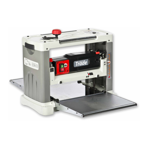
Axminster Trade AT260PT User manual

AT260PT / AT260SPT
AT310SPT
Planer Thicknesser
AT260PT Code 508498
AT260SPT Code 101156
AT310SPT Code 101157
Code: 101157 with Spiral Blades
Code: 508498 with HSS Blades
Code: 101156 with Spiral Blades
Original Instructions
AT&M: 14/09/2018
BOOK REF : 101612

Index of Contents
2
EU Declaration of Conformity
EU Declaration of Conformity 02
What’s Included 03-04-05
General Instructions for 230V Machines 06
Specific Precautions Using Planer Thicknessers 06
Specification 07
Assembly 08-09-10-11
Machine Footprint 12
Illustration and Parts Description 13-14-15-16-17-18-19
Setting up the Machine 20-21-22-23
Operating Instructions 24-25
Changing the Cutter Block Blades 26-27-28-29-30
Maintenance 31-32-33
Exploded Diagrams/Lists:
AT260PT Planer Thicknesser 34-35-36-37-38-39-40-41-42-43-44-45
AT260SPT Planer Thicknesser 46-47-48-49-50-51-52-53-54-55-56-57
Spiral Cutter Block Diagram 58
Wiring Diagrams 59
Cert No: PT107/230 & PT129/230
Axminster Tools & Machinery Ltd
Axminster Devon
EX13 5PH UK
axminster.co.uk
Type Planer Thicknesser
Model AT260PT,
AT260SPT, AT310SPT and conforms to the machinery example for which the
EC Type-Examination Certificate No BM 50314376
has been issued by Laizhou Futian Machinery Co., Ltd.
at: Fenghuang Science and Technology Park, Development Zone Laizhou, Shandong 261400
China
and complies with the relevant essential health and safety requirements.
2006/42/EC
06/42/EC - Annex I/05.2006
EN 60204-1:2006+A1+AC
EN 861:2007+A2
declares that the machinery described:-
This machine complies with the following directives:
EU Declaration of Conformity
Signed
Andrew Parkhouse
Operations Director Date: 27/7/2015
The symbols below advise the correct safety procedures when using this machine.
Fully read manual
and safety instructions
before use
Eye protection
should be worn
Ear protection
should be worn
Two Man
Assembly
HAZARD
Dust mask
should be worn

What’s Included
3
Quantity Item Code: 508498
Part
1 Planer Thicknesser
(with HSS Blades) A
Quantity Item Code: 101156
Part
1 Planer Thicknesser
(with Four Sided Spiral Blades) B
1 Planer Thicknesser Assembly (95% Assembled)
1 Overhead Cutter Guard Mounting Arm Assembly C
1 Cutter Block Guard D
1 Fence Tilt Assembly E
1 Fence F
1 Fence Assembly Mounting bracket with clamping handle and two Cap head Screws G
2 Lift & Shift Handles with M8 threads H
1 Cutter Block Side Guard I
1 NVR Emergency Stop Lever with two Phillips Screws and Nuts J
2 Fence Storage Angle Brackets K
1 Blade Setting Tool L
1 Push Guide Block M
2 Hex Keys 3,4,5mm N
1 Instruction Manual
Quantity Item Code: 101157
Part
1 Planer Thicknesser
(with Four Sided Spiral Blades) B
Model Number: AT260PT
Model Number: AT260SPT
Model Number: AT310SPT
• with HSS 3 Blades
• with TCT Spiral Blades • with TCT Spiral Blades
A
B
B
Continues Over....

What’s Included
4
CD
F
E
G
H
I

What’s Included
5
L
N
K
J
M
Continues Over....

General Instructions for 230V Machines
6
Specific Precautions Using Planer Thicknessers
Most machines currently, are well interlocked to ensure that
the machine must be in the correct configuration to perform
one task or the other. Make yourself familiar with these
configurations and do not try to use the machine in a half
and half state; or rig the interlocks to enable you to do so.
These machines are designed for cutting timber only.They will,
but are not designed to, cut timber derivatives or composites.
Glue lines in plywood, block board etc, will ‘notch’ blades as
sure as eggs is eggs.The bonding agent in chipboard is likewise
detrimental to the health of your planer irons.
It is best to leave them alone. If you have to machine
composites, work out the costs of tungsten, against HSS (plus
the sharpening costs), and proceed accordingly. On larger
machines it is common practice to leave a portion of the blade
(usually the offside 30mm) to be used on‘aggressive’ materials.
Make sure during overhand planing operations, that the fence
is set to the required angle, is securely fastened and locked in
position. Ensure the planer block guarding is in position and
secured.
• Disengage the autofeed for the thicknesser.
• Ensure both tables are correctly seated and locked down.
• Ensure the dust extraction hood is in place and is not blocked.
• Fit dust extraction.
Overhand planing
Check the sharpness of planer irons, check for ‘nicks’ and ‘
notches’, if there are damaged sections on the blades, try to
plane in the ‘clear’ areas. Especially when planing material
down to‘thin’dimensions, maintain pressure on the ‘front’ of
the material i.e., that portion of the stuff that has passed over
the block, but use a push stick or a pusher shoe to clear the end
of the stuff over the block.
Thicknessing
When thicknessing, remove the fence and place the assembly
onto the fence storage brackets to the rear of planer
thicknesser. Lower the thicknessing table slightly. Unlock and
swing both tables ‘up and out of the way’,taking care not to foul
the overhand guard/arm assembly, which will probably swing
free. Turn the dust extraction hood up and over the block.
• Connect the dust extraction. Ensure the hose will not foul
any stuff being passed through the machine.
• Check the height of the thicknessing table.
• Engage the autofeed mechanism.
• Periodically, clean any excess build up of resin from the
thicknessing table, and apply any proprietary brand of
lubricating agent.
NOTE, Consideration should be given to the type of finish you
will be applying to the surface when you select your cleaning/
lubrication agent.
The following will enable you to observe good working
practices, keep yourself and fellow workers safe and maintain
your tools and equipment in good working order.
WARNING!! KEEP TOOLS AND EQUIPMENT
OUT OF REACH OF YOUNG CHILDREN
Mains Powered Tools
• Tools are supplied with an attached 16 Amp plug.
• Inspect the cable and plug to ensuree that neither are
damaged. Repair if necessary by a suitably qualified person.
• Do not use when or where it is liable to get wet.
Workplace
• Do not use 230V a.c. powered tools anywhere
within a site area that is flooded.
• Keep machine clean.
• Leave machine unplugged until work is about to commence.
• Always disconnect by pulling on the plug body and not the
cable.
•Carry out a final check e.g. check the cutting tool
is securely tightened in the machine and the correct
speed and function set.
•Ensure you are comfortable before you start work,
balanced, not reaching etc.
•Wear appropriate safety clothing, goggles, gloves,
masks etc.Wear ear defenders at all times.
•If you have long hair wear a hair net or helmet to prevent it
being caught up in the rotating parts of the machine.
•Consideration should be given to the removal of rings and
wristwatches.
•Consideration should also be given to non-slip footwear etc.
•If another person is to use the machine, ensure they are
suitably qualified to use it.
•Do not use the machine if you are tired or distracted
•Do not use this machine within the designated safety areas
of flammable liquid stores or in areas where there may be
volatile gases.
•Check cutters are correct type and size, are undamaged
and are kept clean and sharp, this will maintain their
operating performance and lessen the loading on the
machine.
•OBSERVE…. make sure you know what is happening
around you and USE YOUR COMMON SENSE.
KEEP WORK AREA AS UNCLUTTERED AS IS
PRACTICAL. UNDER NO CIRCUMSTANCES SHOULD
CHILDREN BE ALLOWED IN WORK AREAS.

Specification
7
Code 508498
Model AT260PT
Rating Trade
Power 2.2kW 230V 1ph
Feed Speed 5m/min
Cutterblock Speed 4,800rpm
Cutterblock Diameter 70mm
Max Thicknesser Capacity 190mm
Max Planing Width 255mm
Max Depth of Cut Thicknesser 2mm
Max Depth of Cut Planer 4mm
Knives 3 x HSS
Length of Table 1,100mm
Min Extraction Airflow Required 1,000m³/hr
Noise Level 89dB
Dust Extraction Outlet 100mm
Overall L x W x H 1,100 x 660 x 940mm
Weight 182kg
Code 101156
Model AT260SPT
Rating Trade
Power 2.2kW 230V 1ph
Feed Speed 5m/min
Cutterblock Speed 4,800rpm
Cutterblock Diameter 70mm
Max Thicknesser Capacity 190mm
Max Planing Width 255mm
Max Depth of Cut Thicknesser 2mm
Max Depth of Cut Planer 4mm
TCT Four Sided Spiral Knives (Replaceable) 44 TCT
Length of Table 1,100mm
Min Extraction Airflow Required 1,000m³/hr
Noise Level 89dB
Dust Extraction Outlet 100mm
Overall L x W x H 1,100 x 660 x 940mm
Weight 182kg
Code 101157
Model AT310SPT
Rating Trade
Power 3.0kW 230V 1ph
Feed Speed 5m/min
Cutterblock Speed 4,800rpm
Cutterblock Diameter 70mm
Max Thicknesser Capacity 225mm
Max Planing Width 310mm
Max Depth of Cut Thicknesser 2mm
Max Depth of Cut Planer 4mm
TCT Four Sided Spiral Knives (Replaceable) 56 TCT
Length of Table 1,380mm
Min Extraction Airflow Required 1,500m³/hr
Noise Level 89dB
Dust Extraction Outlet 100mm
Overall L x W x H 1,385 x 705 x 1,000mm
Weight 272kg

Assembly
8
The planer Thicknesser comes 95% assembled. It is
enclosed in a packing case with all the accessories,
see fig 01. Having removed the top and the sides of
the packing case, remove all the components from the machine,
place safely aside.
Fig 01-02
1. Ascertain the orientation of the machine and move it to its
desired position in the workshop. Make sure its positioned on a
flat level surface and ensure that the machine is positioned to
allow sufficient clearance both in front and behind the machine
to cater for the maximum length of timber you will wish to
machine.
Remember sufficient space must be left ‘around’ the
machine to facilitate your stance when overhand
planing and moving from end to end of the machine if you
are thicknessing single handed. Remember that when the
surface tables are up and out of the way’ for thicknessing,
the machine is appreciably wider than when it is in
overhand mode.
2. The machine is secured down on to the pallet that forms
the bottom of the packing case. Remove these ‘hold down’
brackets, see fig 02. Place lifting straps around the machine, DO
NOT under normal circumstances lift, push or pull the machine
using the tables. Any movement is best carried out against the
main frame cabinet. Hoist the machine clear of the pallet, slide
the pallet out of the way and lower the machine in position.
NOTE: There is four 10mm threaded holes to the underside of
main frame, to attach adjustable machine feet if required. Check
our catalogue or vist our website for details.
Fig 03-04
3. If you do not have the availability of such a hoist, and are
going to have to ‘manhandle’the machine off the pallet; make
sure the tables are locked down before applying any lifting
force to them, see fig 03-04.
4. Before adding the fence and the guarding remove the
protective grease film from the unpainted parts of the
machine. Use a proprietary de-greasing agent. Unfortunately,
this cleaning process is always a bit ‘mucky’, you are advised
to wear overalls or coveralls etc., during the process. Keep in
mind the timber you will be machining and its possible
finishing process, when you choose your anti-corrosion agent.
NVR Emergency Stop Lever
Locate the RED emergency stop lever (J) and remove the two
Phillips screws and nuts.Line up the holes in the hinges with
the ones on the NVR switch housing, insert the Phillips screws
through the hinges and replace the nuts. Lightly tighten
sufficiently to allow the lever to move freely, see fig 05-06-07.
Fig 05-06-07
J
Phillips screw/nut
Hold down bracket

Assembly
9
Overhead Cutter Mounting Arm Guard
1. Locate the overhead cutter mounting arm (C) remove the
lock nut from the threaded bolt, insert the bolt through the
pre-drilled hole to the side of the outfeed table and secure in
place with the lock nut you removed earlier, see fig 12-13-14.
Fig 12-13-14
Cutter Block Side Guard
1. Put to hand the side guard (I), remove the four Hex screws
and washers to the front of the planer thicknesser and place
safely to one side, see fig 08.
2. Place the side guard up against the frame covering the
micro switch and cutter block drive shaft. Line up the holes
in the guard with the threaded holes in the frame and secure
using the Hex screws and washers you removed earlier, see fig
09-10-11.
Fig 08-09-10-11
I
C
Lock nut
Threaded bolt
Pre-drilled hole
J
Continues Over....

Assembly
10
Fig 15
2. Locate the cutter block guard (D). Loosen the locking knob
on top of the mounting plate holder on the mounting arm (C).
Slot the cutter block guard through the mounting plate and
tighten the locking knob, see fig 15.
Mounting the Fence
To mount the fence assembly put to hand the following: The
fence tilt assembly (E), fence (F), fence mounting bracket with
cap head screws (G) and the two lift and shift handles (H).
1. Line up the mounting bracket (G) pre-drilled holes with the
threaded holes mid table to the rear of planer thicknesser and
secure using the two cap head screws, see fig 16-17.
Fig 16-17
2. Loosen the clamping handle on the mounting bracket, insert
the tilt assembly base plate (E) through the mounting bracket
(G) sufficiently for the next step. Lightly tighten clamping
handle, see fig 18. Fig 18
3. Locate the two lift and shift handles (H) and the fence (F),see
fig 19. Position the fence up against the tilt assembly housing
(E). Line up the pre-drilled holes in the mounting plate to the
rear fence assembly (F) with the elongated slots in the tilt
assembly housing (E). Fig 19
Note: make sure the fence is the right way up with the
machined cutout for the cutter block flush against the
tables.
D
Mounting
plate holder
G
Cap head screws
Hex key
Clamping handle
E
Base plate
G
H
F
Mounting plate
Tilt assembly housing
C

Assembly
11
4. Insert the thread of one of the lift and shift handles (H)
through the elongated slot and screw it into the fence
mounting plate, see fig 20.
Note: As space is limited to the rear of the tilt assembly
housing it may be easier to remove the handle from the
threaded bolt, to make it easier to screw on, see fig 21.
5. Replace the handle and secure in place with the Phillips
screw/spring, see fig 22. Repeat for the opposite.
Fig 21
Fig 20
Please note the lift and shift handle has been removed to make
it easier to screw on the threaded bolt.
Fig 22-23
Threaded bolt
Handle
Phillips screw/spring
Washer
elongated slot
H
6. Slide the fence (F) until it’s stop is up against the tilt assembly
housing (E) then tighten the lift and shift handles, see fig 23.
Fence stop
Fence Storage Brackets
1. Locate the two fence storage brackets (K). Loosen the four
cap head screw to the rear of the planer thicknesser. Slot the
cutout key slots to the rear of one of the storage brackets
down over to one of the cap head screws until it locks in place.
Tighten the two cap head screws, see fig 24-25.
Fig 24-25-26
Cap head screws
K
Key slots
Fence
assembly

12
Machine Footprint
Model: AT260PT & AT260SPT Planer Thicknesser
1100mm
600mm
940mm
705mm
1,000mm
1,385mm
Model: AT310SPT Planer Thicknesser

Illustration and Parts Description
13
Fence
Mounting arm
height knob
Outfeed table
Infeed table
Tilt assembly
Table extension
Infeed table
locking handle
Dust extraction
hood
Thicknessing
table rise and fall
control wheel
NVR switch/ emergency
control assembly
Cutter block side guard
Cutter block guard
Main frame
NVR switch assembly (A)
Emergency stop shroud lever (B)
BA
Thicknessing table rise and
fall clamping handle (A)
Thicknessing table rise and
fall control wheel (B)
B
A
Thicknessing table rise and fall scale (A)
Table Pointer (B)
A
B

Illustration and Parts Description
14
Locking lever to engage either
planing or thicknessing function
Cutter block guard angle adjuster (A)
Cutter block guard clamping knob (B)
Cutter block guard (C)
Cutter block (A), Clamping Hex screws (B),
Planer knife (C), Blade holder (D)
Thicknessing
Planing
C
A
B
A
B
C
D
Tilt fence assembly (A), Fence lift and shift
clamping handles (B), Scale (C),
Tilt clamping handle (D) Tilt stop (A)
Adjusting nut (B)
A
B
D
A
B
B
C
Fence Stop (A),
Fence stop clamping Hex screw (B)
A
B
Table extension assembly (A),Table levelling
adjusting bolts (B) Table clamping Hex bolts (C)
AB
C

Illustration and Parts Description
15
Cutter block guard clamp Cutter block
angle adjuster
Fence securing
clamping handle
Fence support
storage bracket
Motor/Drive
access panel
Motor securing bolts
Emergency stop
Outfeed table adjuster (A)
A
Emergency stop Fence angle pointer set to 45˚ (A)
Pointer adjusting screw (B)
A
B

Illustration and Parts Description
16
Infeed table lock
Outfeed table lock
Outfeed table
Infeed table adjuster
Emergency stop
Cutter block guard
Outfeed table adjuster
Cutter block
side guard
Cutter block
Planer blade
Blade holder
Clamping grub screws
Drive roller
Pressure roller
Anti-kick back fingers
Dust extraction
outlet
Pull the spring clip back to release the extraction hood

Illustration and Parts Description
17
Thicknessing table assembly Thicknessing table adjustable stop
Table positioning studs (A),Table lock stud (B) Table locking bar (A)
Four sided Spiral Cutter Block with TCT Spiral Blades Infeed table planning scale
A
B
A
Pointer
Torx head screw
Spiral cutter block
Blade edges

Illustration and Parts Description
18
Fence
Mounting arm
height knob
Outfeed table
Infeed table
Table extension
Infeed table
locking handle
Infeed table
lifting handle
Dust extraction
hood
Cutter block side guard
Cutter block guard
Main frame
NVR switch assembly (A) and Emergency stop (B)
A
B
Thicknessing table
rise and fall scale
Emergency stop control box
with overload trip (RESET) switch
Overload RESET switch

Illustration and Parts Description
19
Outfeed table lock
Cutter block guard
Planing/ thicknessing
fuction lever
Thicknessing table
Thicknessing table
locking handle
Digital thickness
display
Dust extraction hood
Infeed table
Table locking bar (A)
Table micro switch (B)
A
B
Surface table lifting handle
Thicknessing
table rise and fall
control wheel
Motor/Drive access panel (A)
A

Setting up the Machine
20
Digital Thickness Display
Hex key
Straight edge
Tip of blade
Straight edge
Vernier
The ‘Digital Display’ will give an accurate visual indication of
the amount you are adjusting the thicknessing table in 0.10mm
increments.
The digital display should be pre-set at the fatory but if
required can be set as follows.
1. Place a straight edge across the thicknessing table, raise the
table until the tip of the cutter-block blade at it’s lowest point
is touching the top of the straight edge, see fig A-B.
Fig A-B
Fig C
Fig D-E
2. Using a vernier, measure the height of the straight edge
and write down the reading, see fig C. Loosen the grub screw
holding the collar mechanisum, turn the collar on the digital
display unit and dial in the measurement you wrote down, see
fig D-E.Tighten the grub screw, clamping the collar to the drive
shaft.
3. Remove the stright edge from the thicknessing table.
This manual suits for next models
2
Table of contents
Other Axminster Trade Planer manuals
Popular Planer manuals by other brands

GÜDE
GÜDE GADH 254/230 V Translation of original operating instructions

Bartell Global
Bartell Global CONTEC CT320 Owner's manual and parts book

Bosch
Bosch PHO 20-82 Original instructions

Clarke
Clarke CEP1 Operating & maintenance instructions

Dremel
Dremel PL400 Operating/safety instructions

GÜDE
GÜDE GAH 1300 Translation of the original instructions

Makita
Makita M1901 instruction manual

Stomer Professional
Stomer Professional SEP-751 user manual

Mac allister
Mac allister MPTP1500B MAC Original instructions

Scheppach
Scheppach 4902205901 Translation from the original instruction manual

Ryobi
Ryobi AP1300 Operator's manual

King Canada
King Canada 8333 instruction manual